

Page 1
Temeo Hygro Quadro
Art. No. 70-00020
GB
INSTRUCTION MANUAL
Page 2
Attention! For first time operation and battery replacement:
First insert batteries for main unit and then insert batteries for
outdoor sensor.
B
Station
2
C
Wait 5s
5 sec
Service: www.bresser.de/weather
D
Sensor
AAA / LR03
AAA / LR03
AAA / LR03
Page 3
Channel 1
Channel 2
Channel 3
Indoor Sensor
A. B.
3
Page 4
A7
A8
A9
A1 A2 A3 A4 A5
4
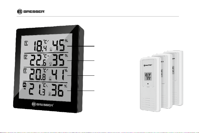
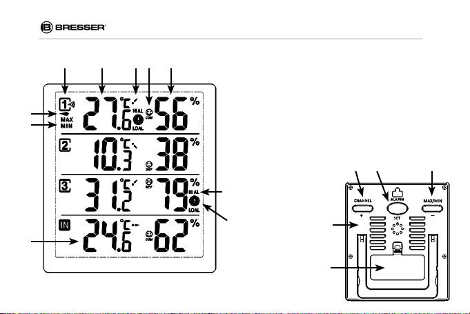
A. Display
A1: Channel number with reception and battery symbol
A2: Temperature
A3: Temperature tendency indicator
A4: Comfort level symbol
A5: Humidity
A6: Hi-/Low-Alarm for temperature /humidity
A7: Marking for selected channel
A8: Symbol for MAX/MIN
A9: Display for internal temperature and humidity
A10: Alarm symbol for temperature/humidity
B. Buttons
B1: CHANNEL/ + button
A6
B2: ALARM/ SET button
B3: MIN/MAX/ - button
A10
B1
B2B1
B2
B3
Page 5
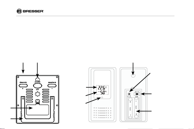
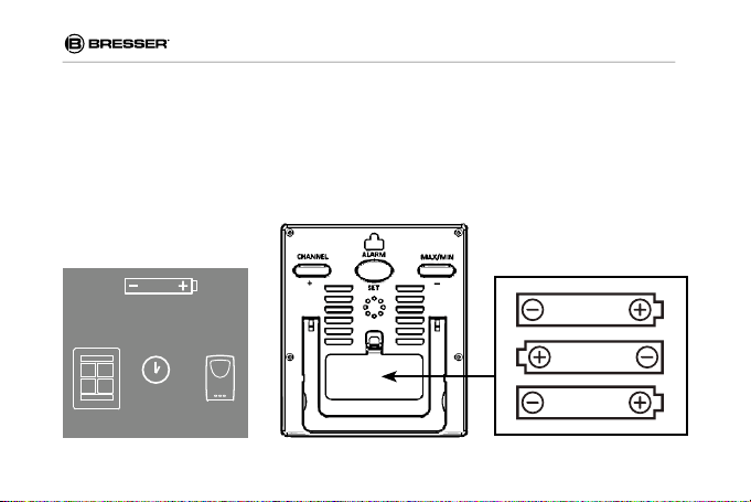
C. Housing
C1: Housing body
C2: Battery compartment (3x AAA battery)
C3: Wall mounting hole
C4: Stand
D. Outdoor Sensor
D1: Display, temperature and humidity
D2: Channel number, as Channel 1, Channel 2, Channel 3
D3: Transmission signal lamp
D4: Wall mounting hole
D5: Battery compartment (2x AAA battery)
D6: °C and °F switch
D7: Corresponding Channel switch
C2
C4
C1 C3
D1
D2
D3
D4
D6
D7
D5
5
Page 6

About this manual
Please read the safety instructions and the user
manual carefully before using the device.
GENERAL WARNINGS
RISK OF CHOKING!
Keep packaging material, like plastic bags and
rubber bands, out of the reach of children, as
these materials pose a choking hazard.
RISK of ELECTRIC SHOCK!
This device contains electronic components
that operate via a power source (Batteries).
Only use the device as described in the manual;
otherwise, you run the risk of an electric shock.
6
RISK of FIRE/EXPLOSION!
Do not expose the device to high temperatures.
Use only the recommended batteries. Do not
short-circuit the device or batteries, or throw
them into a fire. Excessive heat or improper
handling could trigger a short-circuit, a fire or
an explosion.
RISK of property damage!
Do not disassemble the device. In the event of
a defect, please contact your dealer. The dealer
will contact the Service Centre and can send
the device in to be repaired, if necessary.
ATTENTION!
Use only the recommended batteries. Always
replace weak or empty batteries with a new,
complete set of batteries at full capacity. Do
not use batteries from different brands or with
Page 7

different capacities. Remove the batteries from
the unit if it has not been used for a long time.
ATTENTION!
The manufacturer is not liable for damage
related to improperly installed batteries!
SCOPE OF DELIVERY
Main unit (A), Remote sensor (B), Instruction
manual
Required batteries (not included with purchase):
3x AAA / LR03 (1.5V) for Main Unit
6x AAA / LR03 (1.5V) for Outdoor Sensors
INSTALLATION OF MAIN UNIT
1. Open the battery compartment of the main
unit and insert three new batteries 1,5V AAA,
polarity as illustrated.
2. ALL LCD segments will be displayed for
about a few seconds.
3. Close the battery compartment.
INSTALLATION OF OUTDOOR SENSOR
1. Open the battery compartment of the
outdoor sensor with a screwdriver.
2. Insert two new batteries 1,5 AAA, the display
shows the temperature and humidity and the
Channel number 1.
3. Press the °C and °F switch (D6) to select
temperature unit.
4. Use the Channel switch (D7) to change
between Channel 1, Channel 2 or Channel
3. There are a total of 3 outdoor sensors, set
all 3 to different channels.
MAIN UNIT
1. The measurements of the installed outdoor
sensors will be transmitted to the main unit
and the radio-controlled reception symbol
(A1) appears.
2. If the reception is successful, the display
will show temperature and humidity of the
respective outdoor sensor, the temperature
7
Page 8

trend symbol (A3) and the symbol of the
comfort level (A4).
3. Then the radio-controlled reception symbol
disappears.
4. In the display section 4, the measured values
of the internal sensor (Indoor) will appear.
5. If the values are not received from a channel,
‘--’ appears on the display, check the batteries and try it again. Check if there is any
source of interference.
6. You can start the initialization manually.
7. Button function:
(1) CHANNEL / + button
A. Press it to select different display sections.
B. In setting mode, press it equals to UP.
C. Press and hold to enforce radio controlled
reception.
[1] press the CHANNEL/+ button until the
arrow (A7) appears on the desired channel.
Channel 1, 2 or 3, or IN for enforce a radio
8
controlled reception for all outdoor sensors
simultaneously.
[2] press and hold this button for 3 seconds to
search for signals from the desired outdoor
sensor.
[3] the radio-controlled reception symbol (A1)
appears.
[4] the basic station will scan the measurements.
[5] If the reception is successful, the display will
show temperature and humidity of the desired
outdoor sensor, the temperature trend symbol
(A3) and the symbol of the comfort level (A4).
[6] Then the radio-controlled reception symbol
disappears.
(2) MIN/MAX / - button
A. In normal mode, press and hold it more than
3 seconds to switch °C and °F.
B. Press this button, MAX appears on the
display.
C. On the display appear the maximum values
Page 9

since the last reset.
D. Press and hold the MIN/MAX- button to
delete the maximum values of the currently
selected channel.
E. Press this button again
F. MIN appears on the display
G. On the display appear the minimum values
since the last reset.
H. Press and hold the MIN/MAX- button to
delete the minimum values of the currently
selected channel.
I. Press again to go back to the display of the
present values.
NOTE: press and hold the MIN/MAX /- or
CHANNEL / + button for a fast running.
SETTING OF THE ALARM FOR THE
TEMPERATURE AND HUMIDITY
1. Temperature alarm
(1) press the CHANNEL /+ button until the
arrow appears on the desired channel
(channel 1-3, IN)
(2) Press and hold ALARM / SET button for 3
seconds.
(3) HI AL and upper temperature limit (CH
1-3: 70°C - default, IN: 60°C) starts
flashing on the display.
(4) Press the CHANNEL /+ or MIN/MAX
/- button to adjust the desired upper
temperature limit.
NOTE: press and hold the MIN/MAX /- or
CHANNEL / + button for a fast running.
(5) press and hold the ALARM / SET button
after setting the value when still flashing to
activate the alarm function.
(6) The alarm symbol (A10) appears on the
display
9
Page 10

(7) Save the setting with the ALARM / SET
button
(8) LO AL and lower temperature limit (CH
1-3: -50°C【- default, IN: -9.9°C) starts
flashing on the display.
(9) Press the CHANNEL / + or MIN/MAX
/- button to adjust the desired lower
temperature limit.
(10) Press and hold the ALARM / SET button
after setting the value when still flashing to
activate the alarm function.
(11) The alarm symbol (A10) appears on the
display.
(12) Save the setting with the ALARM / SET
button.
2. Humidity alarm
(1) HI AL and upper humidity limit (CH 1-3:
95% - default, IN 95% ) starts flashing on
the display (channel 1-3, IN)
10
(2) Press the CHANNEL / + or MIN/MAX/-
button to adjust the desired upper humidity
limit
(3) press and hold the ALARM / SET button
after setting the value when still flashing to
activate the alarm function
(4) The alarm symbol (A10) appears on the
display
(5) Save the setting with the ALARM / SET
button
(6) LO AL and lower humidity limit (CH 1-3:
20% - default, IN: 20%) starts flashing on
the display.
(7) Press the CHANNEL / + or MIN/MAX /-
button to adjust the desired lower humidity
limit.
(8) Press and hold the ALARM / SET button
after setting the value when still flashing to
activate the alarm function.
(9) The alarm symbol (A10) appears on the
display.
Page 11

(10) Save the setting with the ALARM / SET
button.
DISPLAY OF ADJUSTED ALARM VALUES
1. Press the ALARM /SET button in normal
mode to show the adjusted upper alarm
limits
2. Press again the AL ARM / SET button in nor-
mal mode to show the adjusted lower alarm
limits
3. Press again this button to return to normal
display
DEACTIVATING /ACTIVATING THE ALARM
(1) Press the CHANNEL / + button until the ar-
row appears on the desired channel.
(2) Press and hold ALARM / SET button for 3
seconds.
(3) Upper Temperature Alert limit starts flashing
on the display
(4) In Temperature and Humidity Alarm Mode,
each press of ALARM / SET button rotates
between:
• Upper Temperature Alert
• Lower Temperature Alert
• Upper Humidity Alert
• Lower Humidity Alert
(5) When the above alerts are displayed, press-
ing ALARM/SET button for 3 seconds will
deactivate/activate the corresponding alert.
(6) The alarm symbol (A10) disappears/appears
on the display.
(7) Save the setting with the ALARM / SET but-
ton.
DISABLING WHEN ALARMS ARE ACTIVATED
Press ALARM/SET button to stop the alarm
sound. HI AL or LO AL still flashing on the display.
11
Page 12

COMFORT LEVEL
Temperature range Humidity range
COM 20-28 °C 40-70%
WET >65%
DRY <45%
EC DECLARATION OF CONFORMITY
Bresser GmbH declares that the
device (Weather station/Art.Nr.:
70-00020) is in accordance with
applicable guidelines and corresponding
standards of the 1999/5/EG directive.
CLEANING AND MAINTENANCE
Before cleaning the device, disconnect it from
the power supply (remove batteries)! Only use a
dry cloth to clean the exterior of the device. To
avoid damaging the electronics, do not use any
cleaning fluid.
12
DISPOSAL
Dispose of the packaging materials properly, according to their type, such as paper
or cardboard. Contact your local
waste-disposal service or environmental
authority for information on the proper disposal.
Do not dispose of electronic devices in
the household garbage!
As per Directive 2002/96/EC of the Eu-
ropean Parliament on waste electrical and
electronic equipment and its adaptation into
German law, used electronic devices must be
collected separately and recycled in an environmentally friendly manner.
Page 13

WARRANTY & SERVICE
The regular guarantee period is 2 years and
begins on the day of purchase. To benefit from
an extended voluntary guarantee period as
stated on the gift box, registration on our website
is required. You can consult the full guarantee
terms as well as information on extending the
guarantee period and details of our services at
www.bresser.de/warranty_terms.
13
Page 14

ANL7000020GB0616BRESSER
Errors and technical changes reserved.
Besuchen Sie uns auf • Find us on:
Bresser GmbH
Gutenbergstr. 2 · DE-46414 Rhede
Germany
www.bresser.de · service@bresser.de
 Loading...