

Page 1
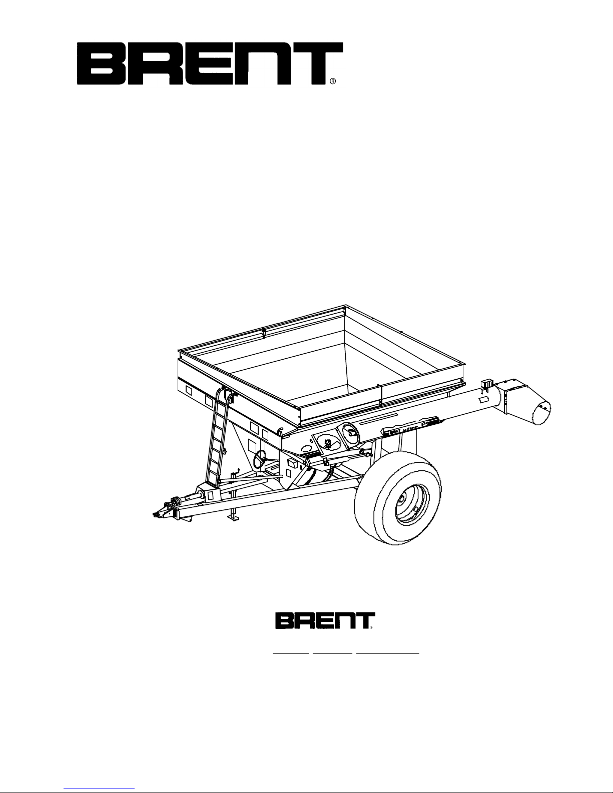
OPERATOR'S MANUAL
PARTS CATALOG
MODELS
674 & 672
Corner AugerTM GRAIN CART
Model 674 Beginning With Serial Number B1651100
Model 672 Beginning With Serial Number B1649100
Manufactured At:
250915H
®
Unverferth
Manufacturing Co., Inc.
27612 Temple Ave.
Shell Rock, IA 50670
PH: 319-885-6571
Fax: 319-885-6576
Part #250475
Page 2

TABLE OF CONTENTS
SECTION I - OPERATION
INTRODUCTION....................................... 1-3
SAFETY .................................................... 1-4
SET UP FOR FIELD OPERATION ........... 1-6
PLASTIC HOSE PIPE INSTALLATION..... 1-7
ELECTRICAL HOOK-UP .......................... 1-8
DUAL WHEELS ........................................ 1-9
TRACTOR HOOK-UP .............................. 1-10
HYDRAULIC HOOK-UP ........................... 1-10
OPERATION IN FIELD ............................ 1-10
AUGER FOLD ADJUSTMENT................. 1-11
HYDRAULIC AUGER OPERATION ......... 1-12
ADJUSTABLE UNLOADING CHUTE ....... 1-13
PAGE
SECTION II - PARTS
PAGE
PTO ASSEMBLY ...................................... 2-2
PTO CLUTCH........................................... 2-3
UNDERCARRIAGE ................................... 2-4
AUGER..................................................... 2-6
BOX & ELECTRICAL................................ 2-8
DECALS ................................................. 2-10
SIDE BOARDS ....................................... 2-11
LOWER AUGER & DRIVELINE .............. 2-12
DRIVE LINE U-JOINT ASSEMBLY ......... 2-13
HUB ........................................................ 2-14
120 - 154" ADJUSTABLE AXLE ............. 2-16
45O GEAR BOX...................................... 2-18
SCALE WEIGHING PROCEDURE .......... 1-13
LUBRICATION, MAINTENANCE .................1-14
SEASONAL STORAGE ...........................1-14
SERVICE TIPS ........................................ 1-15
AUGER.................................................... 1-15
120 - 154" ADJUSTABLE AXLE ............. 1-16
PTO ......................................................... 1-17
OPERATION......................................... 1-17
SHIELDS .............................................. 1-17
JOINTS ................................................. 1-17
SIZE...................................................... 1-18
LUBRICATION ...................................... 1-18
COUPLING PTO DRIVE SHAFT .......... 1-18
CHAINS ................................................ 1-19
CLUTCHES ...........................................1-19
GUARD................................................. 1-20
CONE ................................................... 1-20
QUICK DISCONNECT .......................... 1-21
CLUTCH ............................................... 1-22
DRIVELINE SAFETY PRECAUTIONS ..... 1-23
14" AUGER CYLINDER.......................... 2-19
36" FLOW CONTROL DOOR CYLINDER.. 2-19
HYDRAULIC PTO DRIVE (OPTIONAL) .. 2-20
SCALE (OPTIONAL) ............................... 2-22
ELECTRICAL ............................................2-23
HYDRAULIC DRIVE KIT (OPTIONAL) .......2-24
•
SECTION III - SCALE
SCALE KIT LAYOUT & INSTALLATION ......3-2
SCALE MODEL 2000
OPERATION.......................................... 3-4
OPTIONAL FEATURES ......................... 3-5
INSTALLATION REQUIREMENTS......... 3-6
SHORT-FORM SET-UP/CALIBRATION ..... 3-7
SECTION IV - TARP
TARP PARTS ........................................... 4-2
TARP INSTALLATION .............................. 4-4
• 09-22-03/122904-2
1-2
Page 3

THANK YOU FOR YOUR PURCHASE!
Please fill out and retain this portion for your records. For warranty consideration, please
contact dealer where purchased.
The serial number plate is located on the front side of your Corner Auger
TM
Grain Cart.
Date of Purchase Model Serial #
Owner name Farm/Co. name
Address City
State Zip Code Phone # ( )
Dealer City State
Please supply this information when you have questions or when ordering repair or replacement parts. Your dealer needs this information to give you prompt, efficient service.
INTRODUCTION
Your new Brent Corner Auger
exacting operating requirements. You have chosen a product with numerous
operating features that will increase your harvesting efficiency for years to come.
TM
Grain Cart is designed to meet today’s
A single auger, along with a rugged design throughout, will help keep
maintenance to a minimum. You have also purchased a unit that has other options
as your operation may change; such as a bolt-on axle that allows you to match new
tillage practices and row crop widths. There is an optional electronic scale package
that will provide yield per acre or accumulate bushels per field.
Your new Brent Grain Cart will add the efficiency, flexibility, and dependability
to profit in today’s agriculture.
The following pages will provide you information regarding operating and
maintenance instructions. Use this book to familiarize yourself with this new machine
and provide operating instructions to others.
PRE-OPERATION CHECKLIST
Wheel bolts tightened (re-check after initial use)
Tire pressures checked
Hardware tightened
Machine lubricated
Safety and operating procedures reviewed
Field adjustment information reviewed
Lubrication procedures reviewed
Warranty information reviewed
Guards and shields in place
Hydraulic hoses properly routed/fittings tight
1-3
Page 4

ACCIDENTS
CAN BE PREVENTED
WITH YOUR HELP!
No accident-prevention program can be successful without the whole-hearted
cooperation of the person who is directly responsible for the operation of the equipment.
•
the result before the accident is caused and doing something about it. No power-driven
equipment, whether it be transportation or processing, whether it be on the highway, in
the harvest field, or in the industrial plant, can be safer than the person who is at the
controls. If accidents are to be prevented--and they can be prevented--it will be done
by the operators who accept the full measure of their responsibility.
and they will help, but their combined efforts can be wiped out by a single careless act
of the operator.
Unverferth Mfg. Co., Inc. ask that you be that kind of operator.
A large number of accidents can be prevented only by the operator anticipating
It is true that the designer, the manufacturer, and the safety engineer can help;
It is said that, "the best kind of a safety device is a careful operator." We, at
SAFETY PRECAUTIONS
.
Read this manual carefully before operating.
.
Never enter the grain cart while the auger is running.
.
Make sure PTO guard is kept in place.
.
Never allow anyone on the unit while moving through the field.
.
Be careful when moving unit near electrical lines with discharge auger up.
.
Never tow a loaded unit more than 8 m.p.h. or on a road.
.
Never exceed the maximum recommended hitch pin size which allows for
uneven terrain.
.
Make use of night-time lighting provided on your new cart.
.
Use caution when unloading on the go, while moving through gullies, washouts, and uneven terrain.
.
Always check behind you before backing up.
.
Counter-weight your tractor front end.
.
Be careful on steep slopes. A loaded grain cart is hard to stop.
.
Do not fold or unfold auger while moving.
.
When auger is not in use, be sure to fold to the rest position.
.
Never unhook a grain cart while it is being loaded.
.
Turn the tractor power off and remove the key from the ignition before servicing
the attached implement.
.
Tow only an empty cart on-road and have a rated safety chain attached.
• 12-19-01
1-4
Page 5
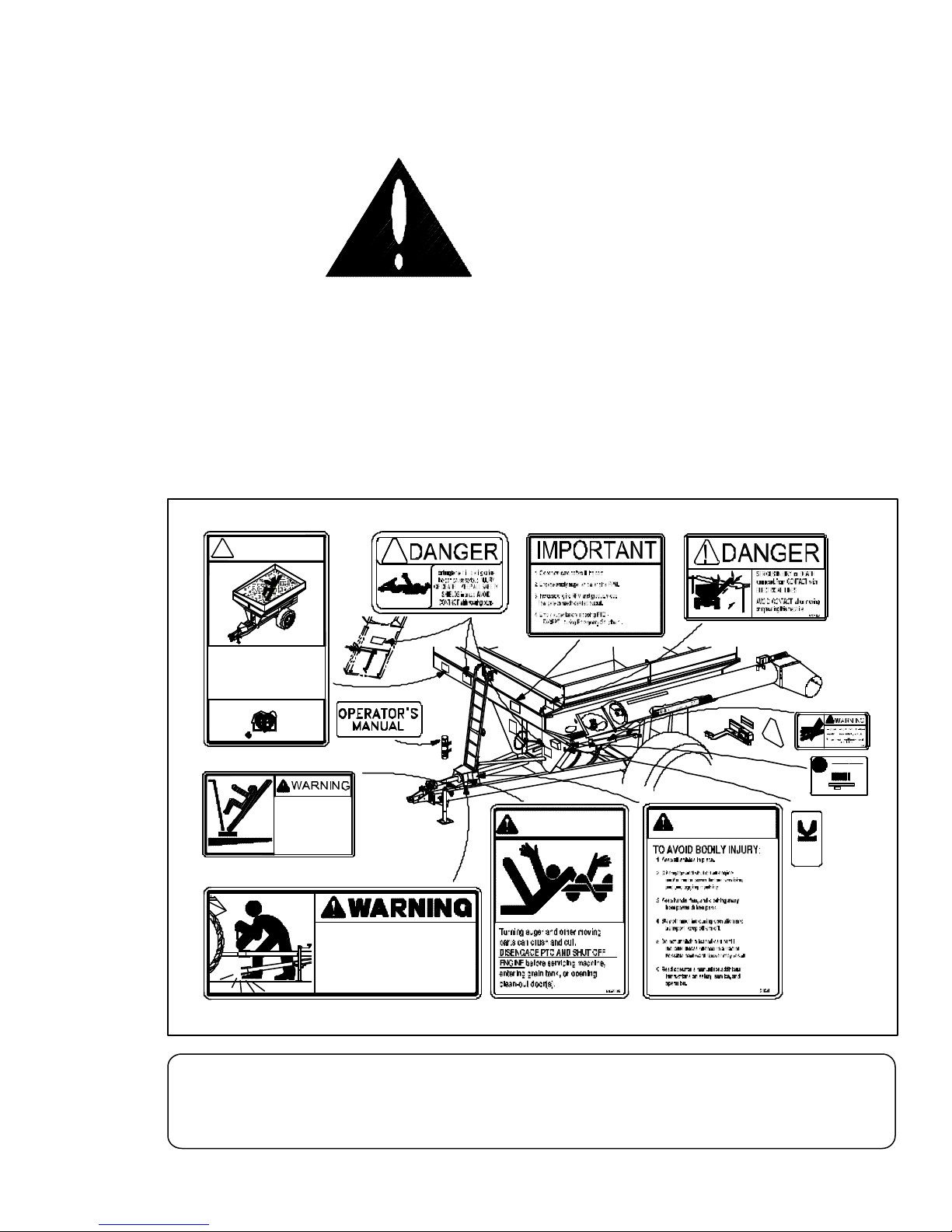
NOTE! This SAFETY ALERT SYMBOL is found throughout this manual. It is used
to call attention to instructions involving your personal safety and the safety of others.
Failure to follow these instructions can result in INJURY OR DEATH.
This symbol means
ATTENTION!
BECOME ALERT!
YOUR SAFETY IS INVOLVED!
SIGNAL WORDS:
DANGER: Indicates an imminently hazardous situation that, if
not avoided, will result in death or serious injury.
WARNING: Indicates a potentially hazardous situation that, if
not avoided, could result in death or serious injury.
CAUTION: Indicates a potentially hazardous situation that, if
not avoided, may result in minor or moderate
injury.
9003478
! DANGER
NEVER PLAY
IN or ON the GRAIN
FLOWING GRAIN TRAPS
and SUFFOCATES
VICTIM in SECONDS !
Farm Safety
Just Kids
9003476
NO RIDERS
FALLING OFF can
cause SERIOUS
INJURY or DEATH
95046
!
9000917
9003478
9003476
TONGUE CAN DROP RAPIDLY
BEFORE REMOVING HITCH PIN,
LOWER JACK STAND INTO POSITION
AND RAISE OR LOWER HITCH TO
TAKE WEIGHT OFF OF THE TONGUE.
9000917
96764
9003477
95046A
9003477
9003475
WARNING
96764
CAUTION
91302
9003474
91605
MEMBER
FEMA
FARM EQUIPMENT
MANUFACTURERS
ASSOCIATION
PRODUCT:
SERIAL NO.
95445
Unverferth
MFG. CO., INC. - U.S.A.
419-532-3121
TM
Replace lost, damaged, painted, or unreadable decals immediately. If parts that have decals are
replaced, also make sure to install new decals. These decals inform and remind the operator
with operational information and safety messages.
• 04-01-02
251924
IMPORTANT
1-5
Page 6
SET-UP FOR FIELD OPERATION
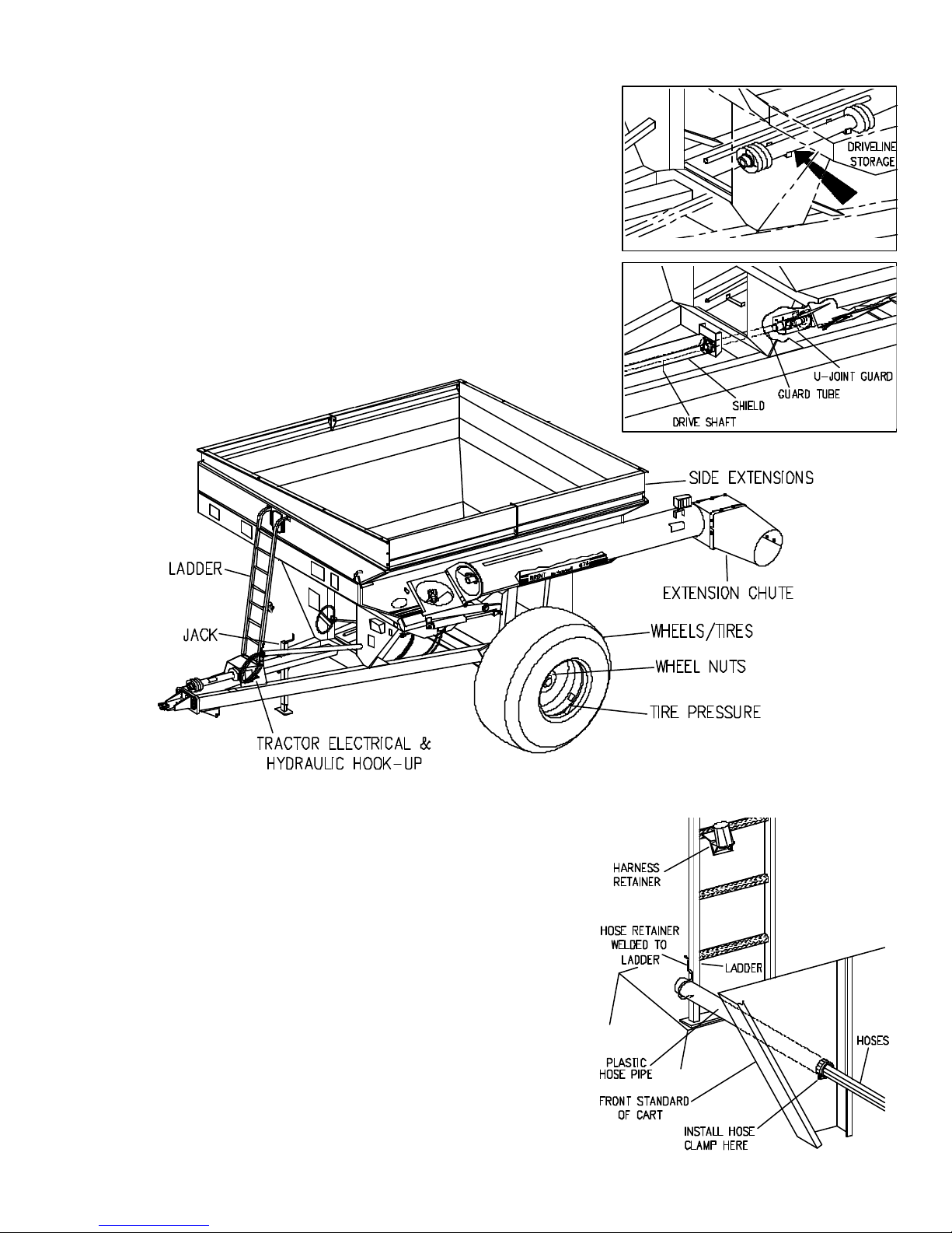
Your grain cart comes set-up with exception of wheel/tire installation, side extensions, ladder,
auger extension chute, electrical hook-up to tractor, and tire pressure check. If your
implement dealer has not set up the preceding items, the procedure is simple.
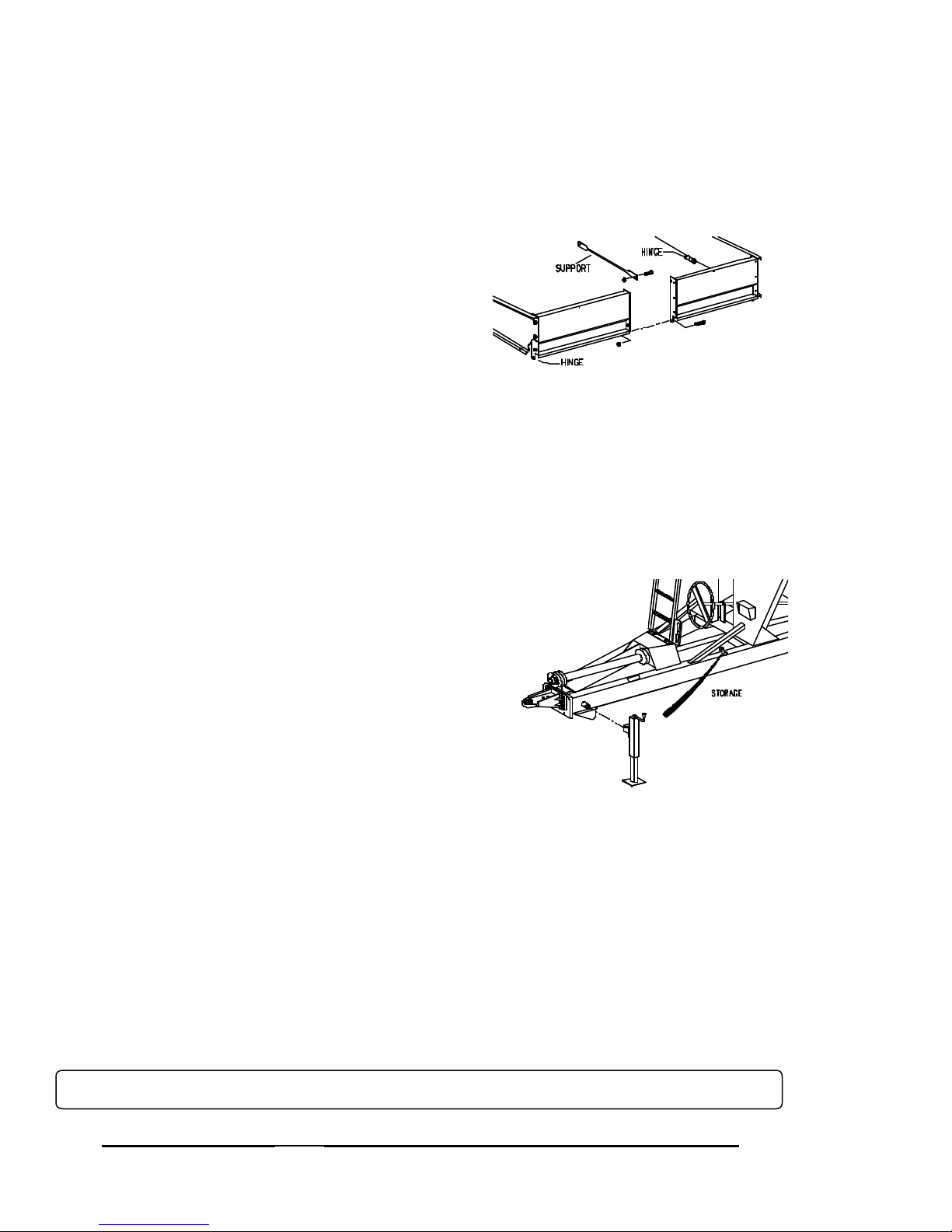
SIDE EXTENSION SET-UP
Refer to parts page in Section 2 for extension placement. Hardware is stored behind right
axle standard of grain cart.
1. Remove transport screws and set extensions
in their respective locations.
2. Secure extension through mounting lug holes
and holes provided in corners.
Folding Boards:
1. Rotate extensions up into position and secure
at corner holes.
2. Attach center support hardware.
3. Tighten all hardware, including hinge bolts.
AUGER EXTENSION CHUTE
Position outlet shroud & chute assembly over the upper auger tube. Check trim lock seals for
proper seating and contact. Hold with capscrew in top center hole and secure with nine
capscrews, flatwashers and locknuts.
AUGER EXTENSION CHUTE
Position outlet shroud & chute assembly over the upper auger tube. Check trim lock seals for
proper seating and contact. Hold with capscrew in top center hole and secure with nine
capscrews, flatwashers and locknuts.
251903
LADDER
Set ladder over mounting lugs and secure to front panel of
cart.
JACK
Use jack to support an empty grain cart, never a loaded
grain cart.....always have a loaded grain cart hooked to
tractor. Remove jack from storage on inside of left frame
and install on mounting spud behind hitch. Important:
Return jack to storage location after cart is hitched to
tractor.
WHEEL NUTS
234912
Check all wheel nuts for tightness before first load. Failure to do so may damage wheel nut
seats. Once seats are damaged, it will become impossible to keep nuts tight. Tighten nuts
to 400 ft. lbs. Re-tighten after first three loads and check periodically during first season of
use.
TIRE PRESSURE
The following is to be used as a general guide for tire inflation and figures can vary depending
on specific brand of tire used. It is important that tires are inspected after unit is loaded. The
tire should stand up with no side wall buckling as tire rolls.
24.5 x 32 38 Lbs.
30.5 x 32 33 Lbs.
18.4 x 38 37 Lbs.
20.8 x 38 37 Lbs.
18.4 x 42 37 Lbs.
420/80 x 46 29 Lbs.
For questions regarding new tire warranty, please contact your local original equipment tire dealer. Used tires carry
•
no warranty. Tire manufacturers' phone numbers and websites are listed on page 1-24 for your convenience.
VERY IMPORTANT..........
NEVER tow a loaded grain cart in excess of 8 m.p.h.
• 04-01-02
1-6
Page 7
SET-UP
DRIVELINE STORAGE
Storage brackets are located on the inside right
frame rail. Secure the PTO shaft to these brackets for extended transporting or seasonal
•
storage. IMPORTANT: Remove and store the
complete PTO before towing grain cart behind a
delivery truck. Interference could occur when
turning resulting in damage to PTO and cart.
DRIVE SHAFT SAFETY GUARDS
The PTO drive shaft shield, floating guard tube
and U-joint guard are factory installed. Make
sure they are in place before operating the
auger.
233926
234912
PLASTIC HOSE PIPE INSTALLATION
Place plastic hose pipe through the front
standard and hose retainer on ladder.
Slide the hoses through the plastic hose
pipe. Set a desired hose length. Fasten
the hoses and plastic hose pipe with the
hose clamp behind the front standard.
The wiring harness will also be run
through the plastic hose pipe. Fasten
harness to the hoses with tie straps.
NOTE: It is recommended that any excess hose or wiring harness be contained at the rear of the hose pipe.
• 10-03-01
250915H
250915
1-7
Page 8
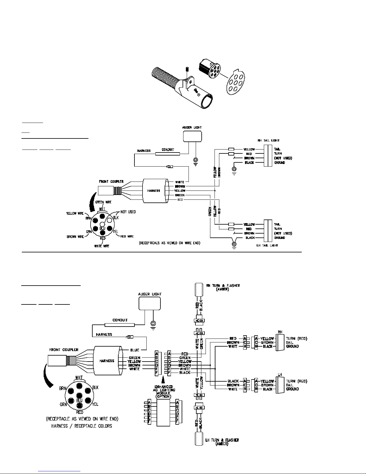
ELECTRICAL HOOK-UP
Your Grain Cart is supplied with a seven-point SAE connector plug which will adapt
to the receptacle found on several new tractors on the market today. If not available,
an SAE J S60A seven-point outlet socket can be purchased from your Unverferth
dealer (order Part #92824).
SAE SEVEN-POINT
CONNECTOR PLUG
220912
NOTE: It may be necessary to install a switch in the tractor to operate the auger light.
672
674 S/N B19380099 & LOWER
GRAIN CART WIRES
Green -- Ground
Brown -- RH amber flasher
Red -- LH amber flasher
White -- Auger light
Yellow -- Tail light
220913
The following schematic complies with ASAE Standard S279.11 for new production
tractors. NOTE: Wiring specifications may be different for older tractor models. Consult
your tractor operator's manual or dealer for proper wiring and installation.
674 BEGIN S/N B19380100
GRAIN CART WIRES
White -- Ground
Green -- RH amber flasher
Yellow -- LH amber flasher
Brown -- Tail light
Red -- RH red flasher
Black -- LH red flasher
Blue -- Auger light
251908
• 09-10-02
1-8
Page 9
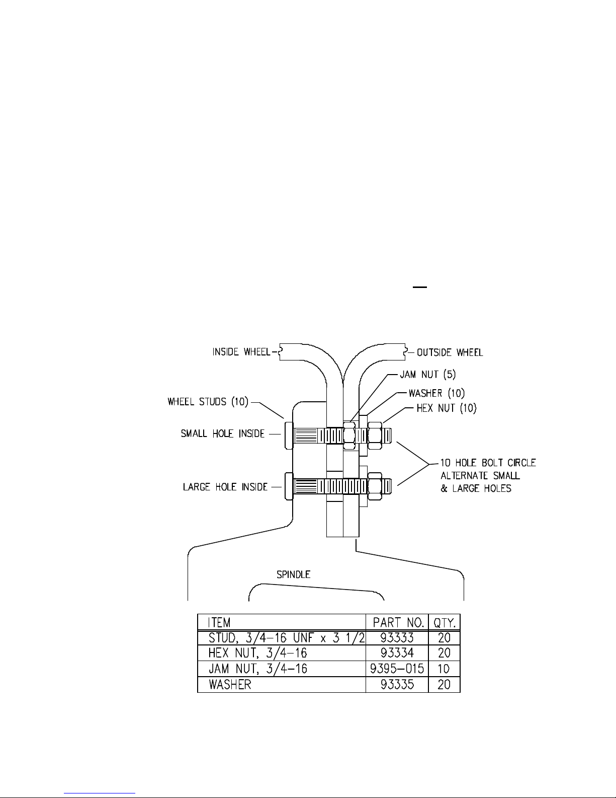
DUAL WHEELS
SPINDLE
1. If necessary, replace existing wheel studs with longer 3/4-16 UNF x 3 1/2" studs.
INSIDE DUAL WHEEL:
2. Install inside dual wheel.
3. Use 3/4-16 hex jam nuts (27/64" Thick) on small holes.
4. Tighten the five jam nuts to 200 Ft. Lbs.
OUTSIDE DUAL WHEEL:
5. Install outside dual wheel with the five large holes indexed over inside wheel
nuts.
6. Use washers and 3/4"-16 UNF Grade 8 nuts on all studs.
7. Tighten the ten nuts to 400 Ft. Lbs.
•
•
• 04-16-01
250923
1-9
Page 10
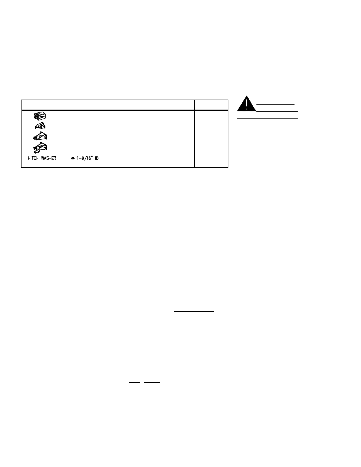
TRACTOR HOOK-UP
-- Make sure sufficient counter-weight is used on the tractor's front-end.
-- Move draw bar into closest position for even terrain.
-- Make sure draw bar length and PTO telescoping limits are adequate for
•
uneven terrain, gullies, rice levees etc.
-- Never exceed the maximum recommended hitch pin size which allows for
uneven terrain. See Chart below.
-- Install hardened washer of hitch pin diameter between bottom of swivel ball
and tractor draw bar.
HITCH PIN SIZE
A CLEVIS, RIGID (Scale Only) 1 1/4"
•
250960
B SINGLE TANG SWIVEL (Scale Only) 1 1/2" / 2"
C SINGLE TANG SWIVEL (Non-Scale) 1 1/2"
D SINGLE TANG SWIVEL & HAMMERSTRAP (Non-Scale) 1 1/2"
PIN IN BALL SWIVEL.
FAILURE TO USE THE
RECOMMENDED HITCH
PIN SIZE AND APPROPRIATE WASHER CAN CAUSE
PREMATURE FAILURE OF
SWIVEL BALL AND
TRACTOR DRAWBAR.
IMPORTANT!!
USE FULL SIZE
HYDRAULIC HOOK-UP
-- Properly identify the hoses for the auger fold and the flow control operation.
-- It is advisable to use the hydraulic control lever closest to the operator (most
commonly known as control lever No. 1) to activate the flow control.
OPERATION IN FIELD
1. Make sure the flow control door is in the closed position before loading into the
cart.
2. Engage PTO at a low RPM; increase tractor RPM to desired speed.
3. Open the flow control to desired rate.
4. Use the flow control opening to slow the rate of the flow rather than the tractor's
RPM. NOTE: If overload causes the clutch to slip (standard PTO drive) or
motor to stall (hydraulic drive), stop auger immediately. Excessive heating of the
clutch will require replacement of internal parts. Close flow control door and
relieve auger unload pressure by opening bottom pit dump door to remove some
grain from auger.
5. It is not advisable to disengage the auger with the flow control open. Excessive
start-up torque may result, putting stress on the cart driveline and your tractor.
6. Properly identify the tractor remotes as to hook-up the flow control and auger
fold. A mix-up can damage the auger drive system.
7. Under any circumstances, DO NOT enter the cart with the auger or tractor
running.
8. When folding the auger into the unloading position, make sure you have given
sufficient time for the cylinder to rotate the bell crank into an over-center
position.
9. It is strongly advised that the unloaded auger always be returned to the transport
position when not in use.
• 04-16-01
1-10
Page 11
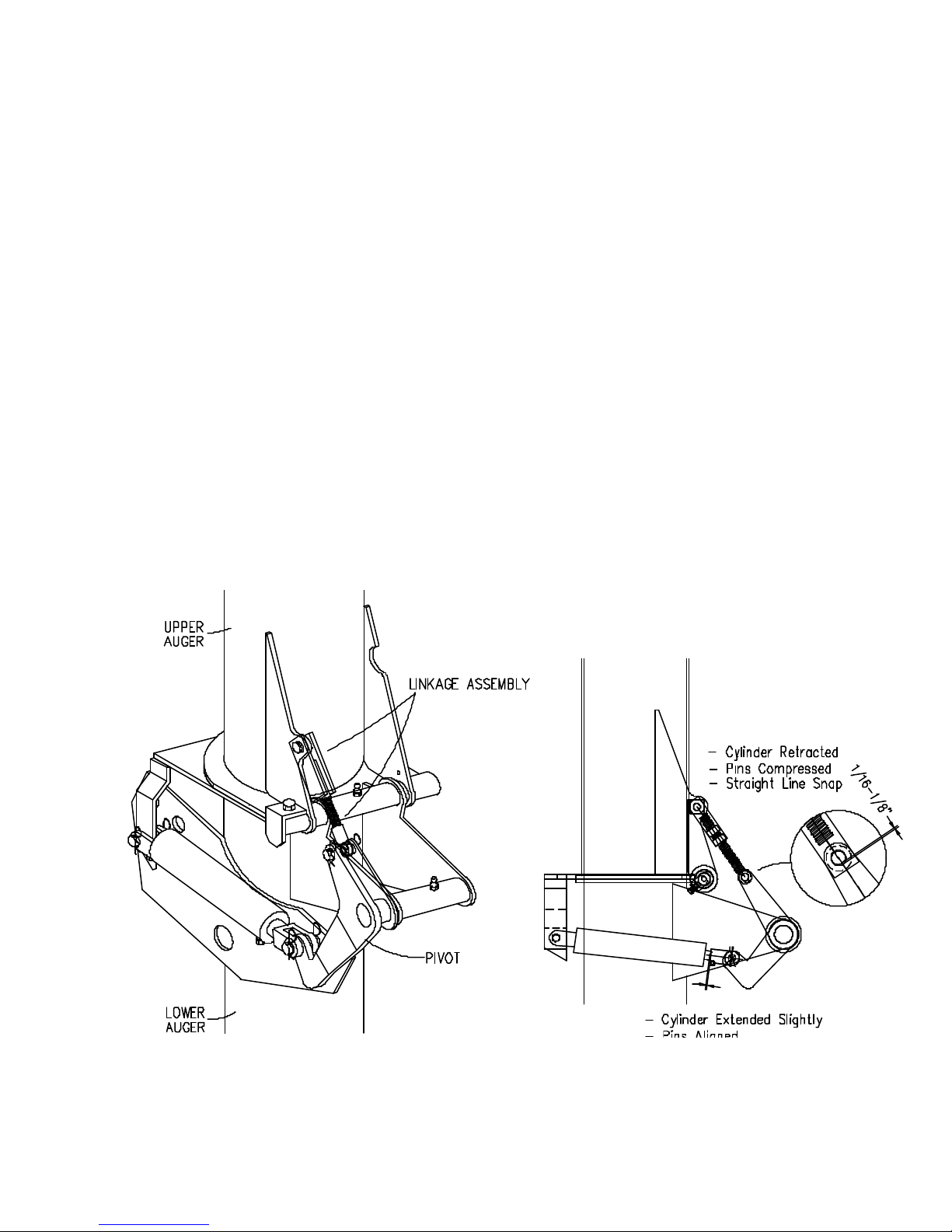
AUGER FOLD ADJUSTMENT
The auger fold linkage is adjusted at the factory and under normal operating conditions
should not require adjustment. Disassembly for service or slight wear in the linkage pins may
necessitate the need for adjustment. The 1/8" compression dimension is necessary for a good
seal at the auger flanges and snap locking at the end of the cylinder stroke.
1. Fold the upper auger into the operating position and clamp flanges to secure.
2. Extend hydraulic cylinder slightly (1/8") to relieve load. Remove T-Bar yoke pin.
3. Retract cylinder to end of stroke.
4. Rotate T-Bar yoke as necessary to position rockshaft arm hole approximately 1/8" past T-
Bar yoke holes when T-Bar linkage and rockshaft arm are in a straight line.
5. Extend cylinder slightly again to line up holes in T-Bar yoke and rockshaft arm. Install pin
and secure with nut. Remove temporary clamp before cycling auger fold operation.
6. Retract hydraulic cylinder. Check for sealing at auger tube flanges and for "straight-line
lock snap" of linkage. Cycle linkage by fully lowering and raising auger tube. Recheck
linkage. Readjust as necessary.
• 06-30-00
251909
1-11
Page 12
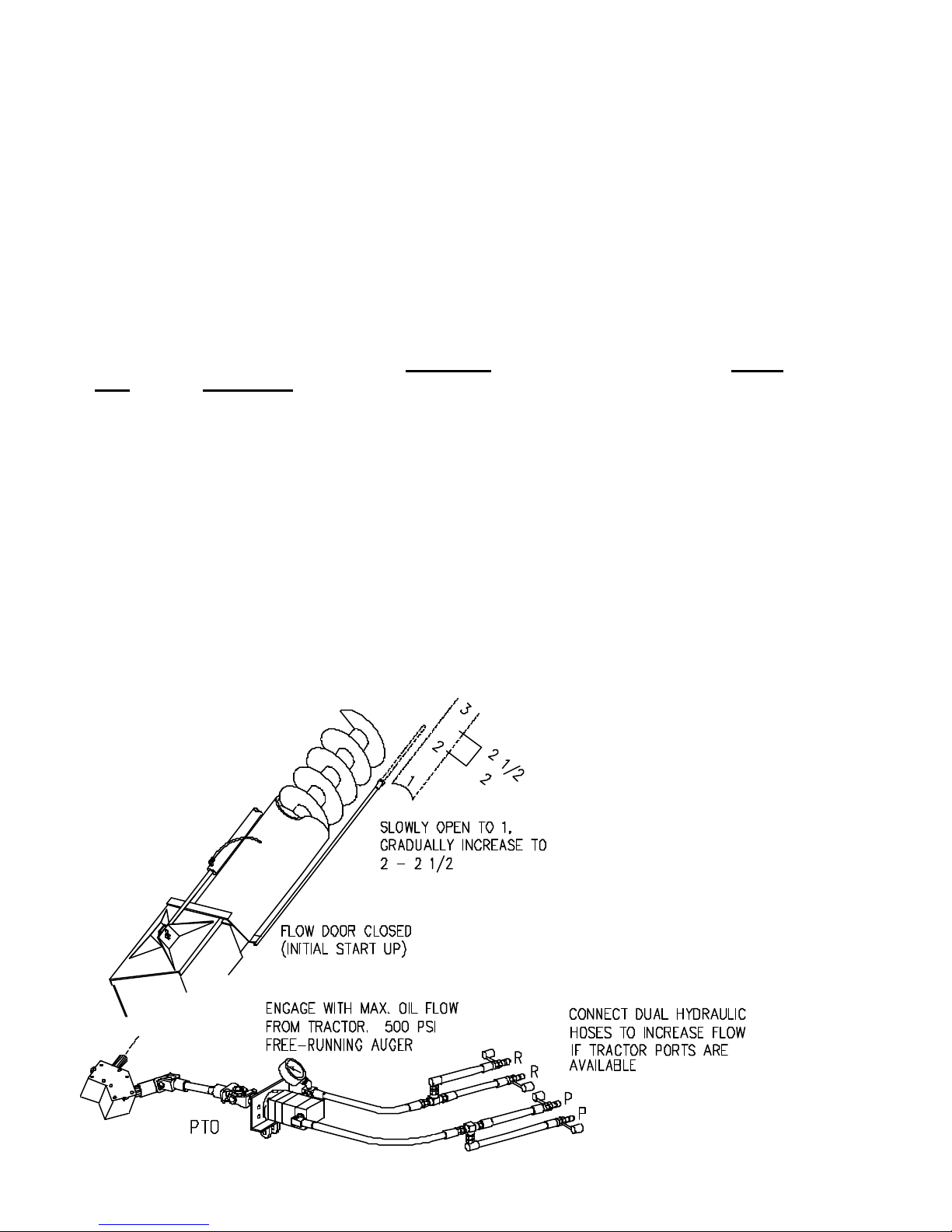
HYDRAULIC AUGER OPERATION
For PTO & DIRECT DRIVE Applications
1. Initial start-up: Flow Door is to be closed.
2. With flow door closed, engage hydraulic motor with maximum oil flow from
tractor. NOTE: Free running auger oil pressure will range 500 PSI or less.
3. The pressure gauge will register system work load as flow door is opened.
Slowly open flow door to #1 setting on auger tube decal gauge. While
monitoring the auger discharge rate and hydraulic pressure, gradually increase
flow door opening to approximately 2 - 2 1/2 setting. Watch the pressure gauge
and stop opening door once pressure reaches 2000 PSI.
4. Peak performance is obtained by matching your highest continuous auger
rpm to the flow door opening setting. It is necessary to initially monitor the
auger speed and adjust the flow door UP or DOWN to arrive at the optimum
output performance. If the flow door is opened too wide, the oil pressure will
rise, but the GPM and the hydraulic motor RPM could slow down - resulting in
less auger output. Also if the tractor has a higher GPM output, it is possible that
the flow door could be opened wider and still maintain performance.
5. Bushels-per-minute output depends on the following factors:
a. Oil flow (GPM) from tractor.
b. Flow door opening setting.
c. Grain moisture content.
6. The hydraulic motor is capable of handling 32 to 35 GPM. If extra hydraulic
ports are available on the tractor, it is possible to increase oil flow to the
hydraulic motor by teeing together two pressure ports to the single pressure
hose, and teeing two hoses from return hose to the tractor return ports.
250946
• 09-09-96
1-12
Page 13
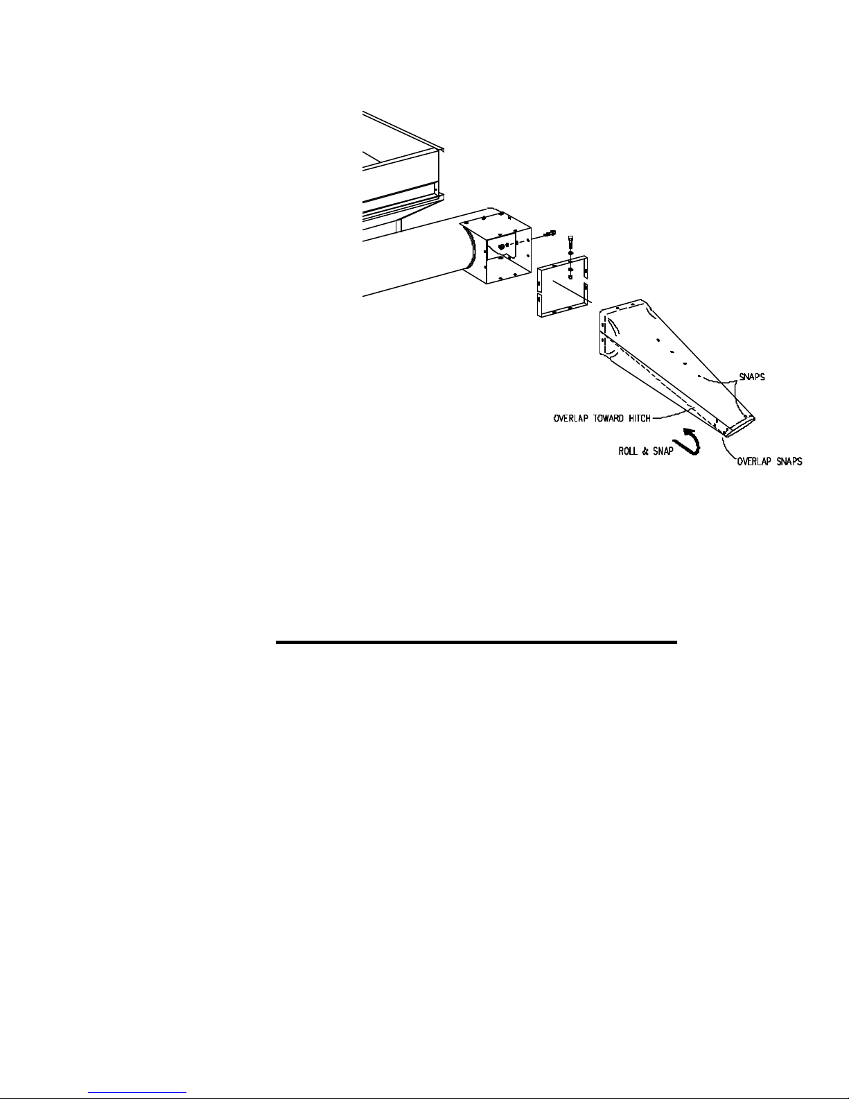
ADJUSTABLE UNLOADING CHUTE (OPTIONAL)
INSTALLATION:
1. Remove existing chute.
2. Fold overlap and snap four end snaps.
3. Slide chute over outlet shroud with
overlap towards hitch.
4. Install top and bottom strips over chute
and fasten with existing capscrews,
flatwashers and locknuts.
5. To adjust to desired length, unsnap
overlap, roll chute on outside and snap
in place.
SCALE WEIGHING PROCEDURE
250957
Turn scale on and let it warm-up at least 15 minutes.
Zero balance scale by pushing the "Net/Gross" button, and then the "Zero" button
within 3 seconds. This should be done where cart is going to be unloaded (on level
ground if possible).
Load cart and let scale total up weight. When cart is full drive up to truck and stop.
After scale settles on a number, push the "Tare" button. Scale indicator will show zero.
Now start unloading cart. When truck is full or cart is empty, the negative amount
shown on scale is actual product in truck.
Now push the "Net/Gross" button. This will put the scale back into the gross
weighing mode again. If the cart has grain in it yet, it will tell you how much weight is
left on the cart. You can now load the cart again and repeat the same unloading process. You should try to get the cart empty a few times during the day so you can rebalance the scale.
• 06-30-00
1-13
Page 14
250922A
250950
SEASONAL STORAGE
Fully open flow door to retract and protect Flow Door Cylinder rod. Apply thin coating
of General Purpose grease or spray equivalent to Auger Cylinder rod (extended in
folded rest position).
8 hrs 20 hrs
• 05-09-97
1-14
Page 15
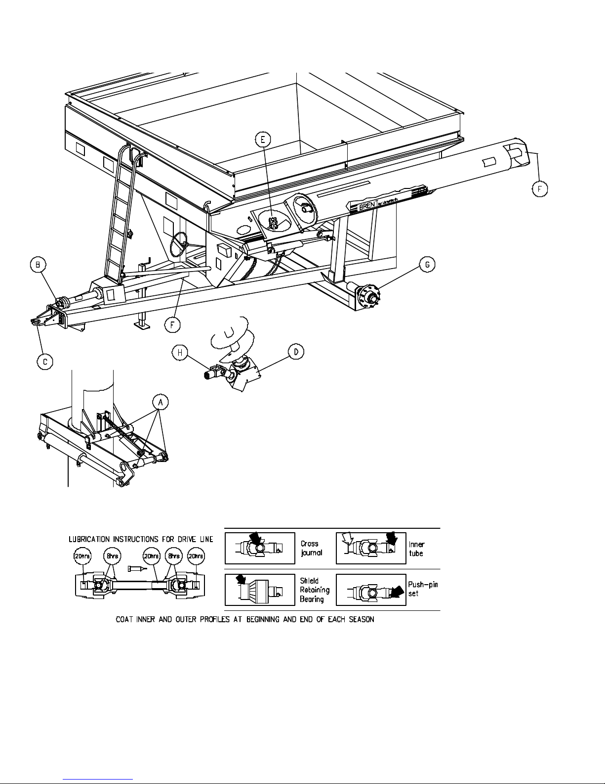
LUBRICATION AND MAINTENANCE
To keep your grain cart in top operating condition and to assure its proper
performance and reliability for a long period of time, a periodic inspection and
lubrication is a must.
The lubrication locations and recommended schedule are as follows:
A. Three shots of grease weekly
B. See chart
C. Roll bearing and apply grease as required. Do not grease if cart has scale unit.
•
D. Replace every season, 1 1/2 pints 90 weight oil
E. One shot of grease daily
F. One shot of grease per season
G. Repack once every 2 years; adjust bearing take-up once per season
H. Three shots of grease per week
SERVICE TIPS
DRIVELINE
It is important to periodically check set screws
in all bearings at either end of the driveline
for tightness.
U-JOINT
The U-joint will give you several years of
service if the following steps are taken:
1. Grease joint weekly
2. Grease spline weekly
GEAR BOX
-- Fluid level plug is on the right side of
gear box
-- Fill plug is in front of the axle on the left
side of gear box (Standing behind the
cart looking toward the tractor)
For maximum gear box life :
-- Check oil level every 2 weeks
-- Replace oil every season, 1 1/2 pints 90
weight oil
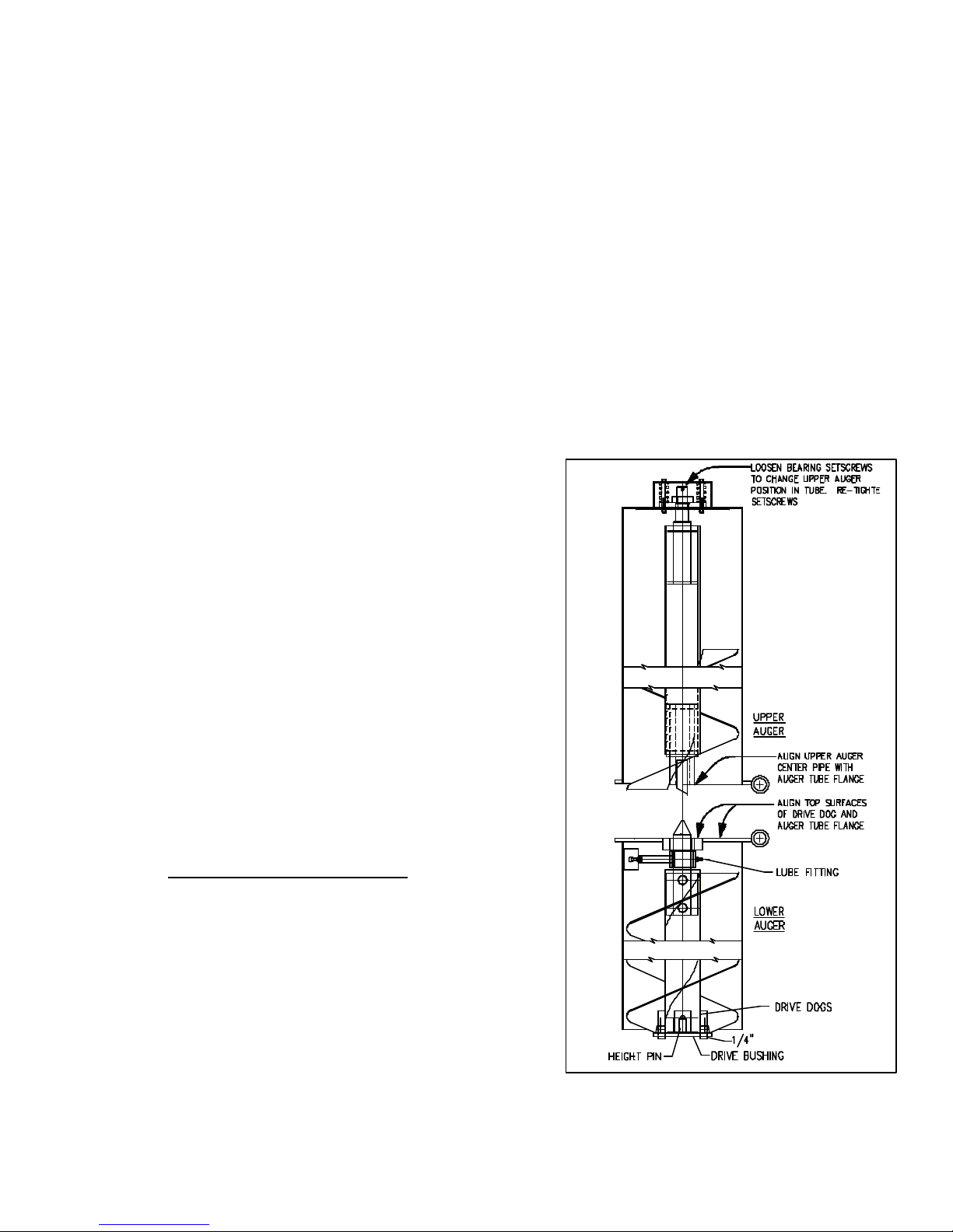
AUGER SYSTEM
Annually check all bolts, nuts, and set screws.
Perform lubrication as specified. NOTE:
The lower auger position is indexed from the
drive dog / tube flange hinge surface as
250914
shown. The lower drive dogs and height pin
are positioned relative to the gear box and drive bushing. The alignment height of
•
the auger can be changed by cutting loose and relocating the height pin.
• 05-20-96
1-15
Page 16
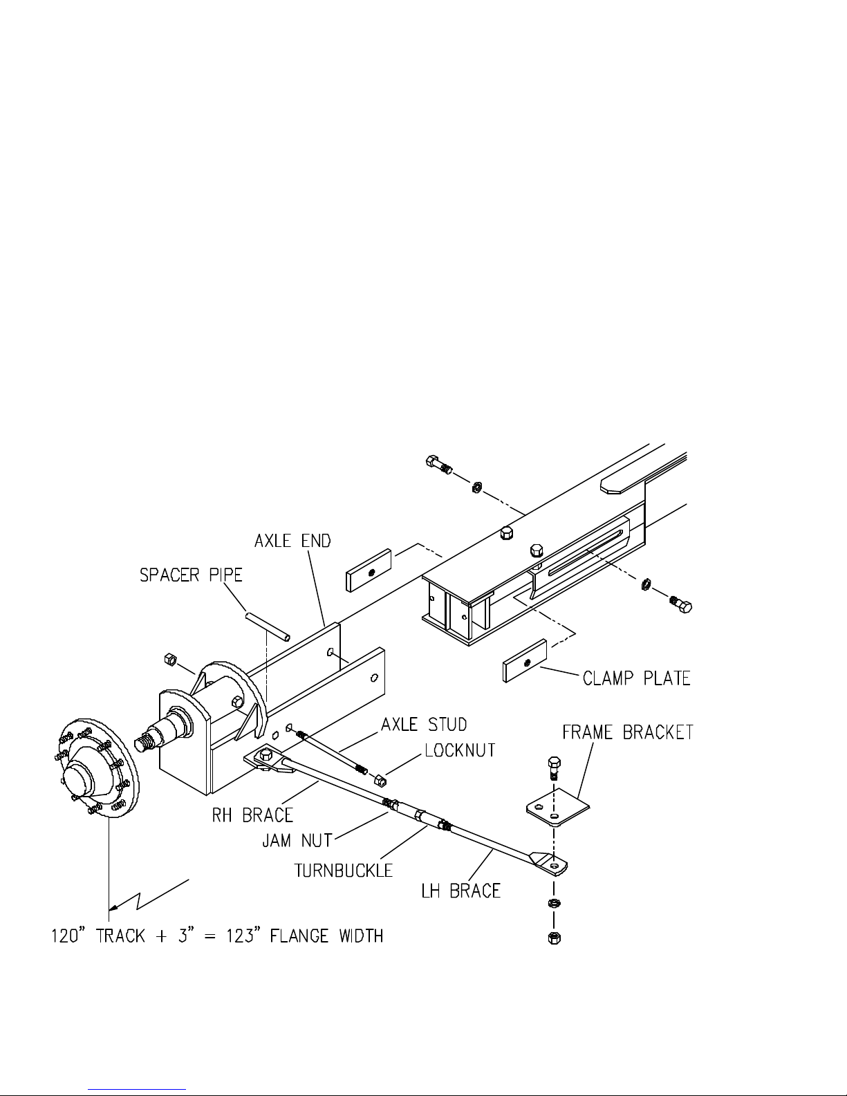
ADJUSTABLE AXLE - MODELS 672, 674
ADJUSTABLE AXLE (120" - 154")
1. Raise center axle weldment.
2. Loosen clamp plate capscrews on slotted slides of axle weldment
3, Extend axle to desired width and align holes for studs if greater than 144".
4. Remove axle stud and spacer pipe from storage brackets on rear of axle.
Install in outer set of holes for desired axle width.
5. For an axle width of 144" or greater, move axle brace assemblies from front to
rear holes on frame bracket. Loosen setscrews in turnbuckle and adjust to fit the
extended axle ends. Tighten setscrews.
250965
• 05-09-97
1-16
Page 17
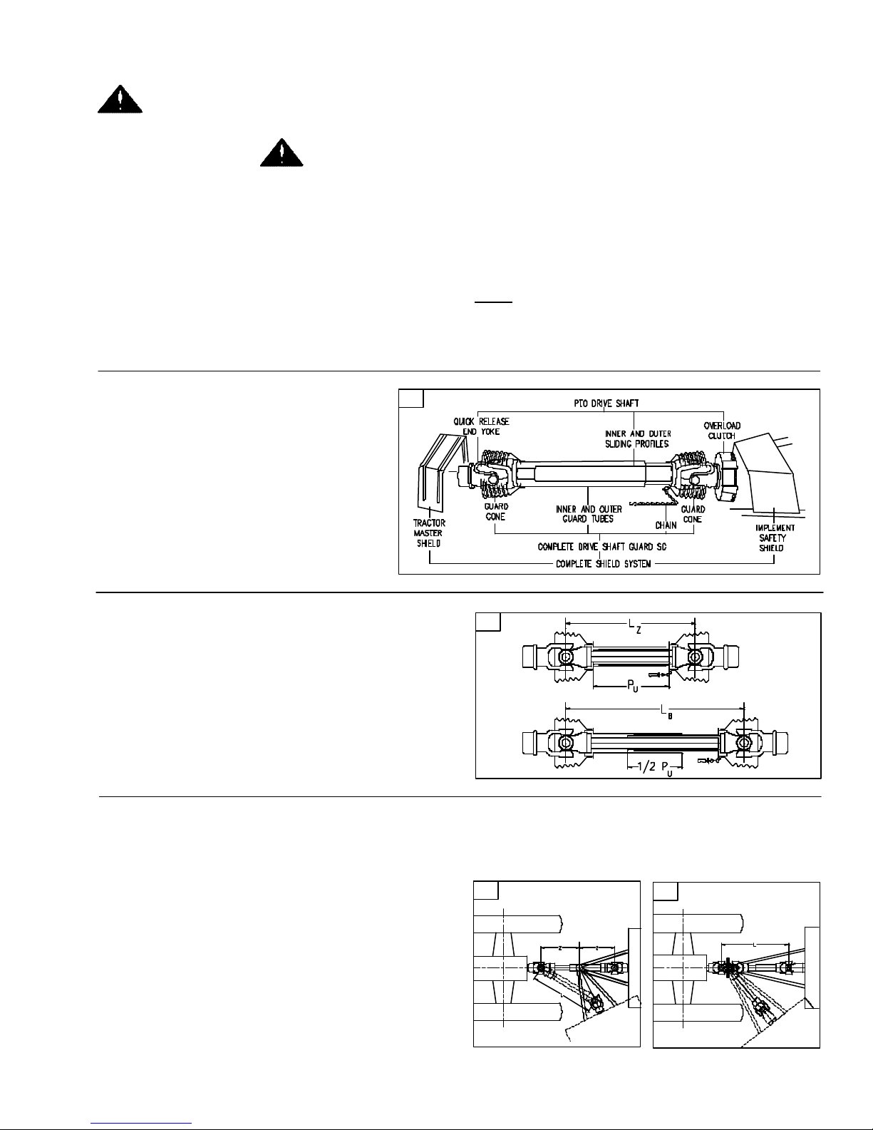
PTO SHAFT & CLUTCH
This Safety Alert Symbol means Attention!
Become Alert! Your safety is involved!
OPERATING THE PTO
When finishing operation of PTO driven equipment,
shift PTO control to neutral, shut off the engine and
wait until the PTO stops before getting off the tractor
and disconnecting the equipment.
Do not wear loose clothing when operating the power
take-off, or when near rotating equipment.
When operating stationary PTO driven equipment,
always apply the tractor parking brake lock and block
the rear wheels front and back.
To avoid injury do not clean, adjust, unclog, or
service PTO driven equipment when the tractor engine is running.
Never exceed the recommended operating speed for
the particular equipment in use.
PTO drive shafts must only be used for their intended purpose.
PTO drive shafts, clutches and freewheels are designed for specific machine types and power requirements. They must not be replaced by other models.
NOTE: The tractor and implement manufacturers'
operating instructions.
Ensure that the PTO shaft is securely connected.
A. Only use a completely shielded drive
system:
PTO drive systems with complete
shielding, include the tractor master
shield and implement shielding installed
all the time. If any component of the
shield system has been removed for
any reason it, or a repair part, must be
installed before operation.
B
Try to obtain the greatest possible overlap without
bottoming out in the maximum operating condition. In its working position, the PTO drive shaft
should not be extended by more than half the
telescoping member overlap PU available when
fully compressed LZ. (See diagram on inside
cover).
A
250968A
!
BB. Note the maximum operating length L
250968B
C. Maximum joint angles:
1. Joint (standard type)
Continuous operation 25
Short duration 45
Stationary 90
o
o
o
2. Wide-angle CV joint
Continuous operation 25
o
Short duration 70/80
Stationary 70/80
Check shaft articulation and clearance zone! Joint
articulations of more than 70/80 degrees leads to
damage.
Ensure equal joint
angles! Switch off
}
PTO if joint angles
are too large and
unequal!
o
(depending on design)
o
(depending on design)
Contact between PTO drive shaft and tractor or
implement (e.g. three point hitch, drawbar) leads to
damage.
C1
250968C
C2
1-17
Page 18
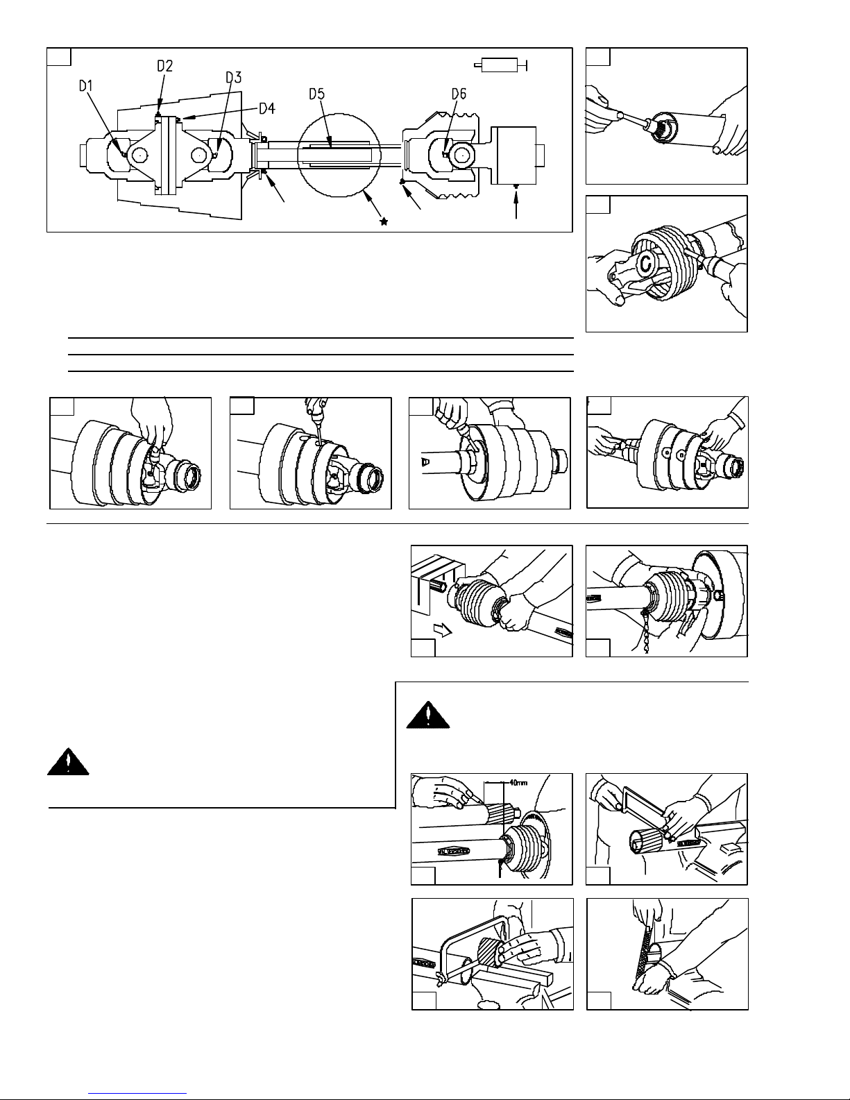
D
D. Lubrication (Figs. D1 - D6)
Lubricate with quality grease before starting work and every 8 operating hours.
Clean and grease PTO drive shaft before each prolonged period of non-use.
Molded nipples on the shield near each shield bearing are intended as grease
fittings and should be lubricated every 8 hours of operation!
Telescoping members must have lubrication to operate successfully regardless
of whether a grease fitting is provided for that purpose! Telescoping members
without fittings should be pulled apart and grease should be added manually.
Check and grease the guard tubes in winter to prevent freezing.
D5
D6
D1
250968D
E. Coupling the PTO drive shaft (Figs. E1 - E2)
Clean and grease the PTO and implement input
connection (IIC)
AS-Lock
1. Pull locking collar and simultaneously push PTO
drive shaft onto PTO shaft until the locking device
engages.
Push-Pull Lock
2. Pull locking collar and simultaneously push PTO
drive shaft onto PTO shaft until the locking device
engages.
Check to insure all the locks are securely
engaged before starting work with the PTO
driveshaft.
D3
E1
D4D2
E2
250968E
Check the length of the telescoping members
to insure the driveline will not bottom out or
separate when turning and/or going over rough terrain.
F. Length adjustment (note: maximum operating
length LB). (Figs. F1 - F4)
1. To adjust length, hold the half-shafts next to each
other in the shortest working position and mark
them.
2. Shorten inner and outer guard tubes equally.
3. Shorten inner and outer sliding profiles by the
same length as the guard tubes.
4. Round off all sharp edges and remove burrs.
Grease sliding profiles.
1-18
F1 F2
F3
F4
250968F
Page 19
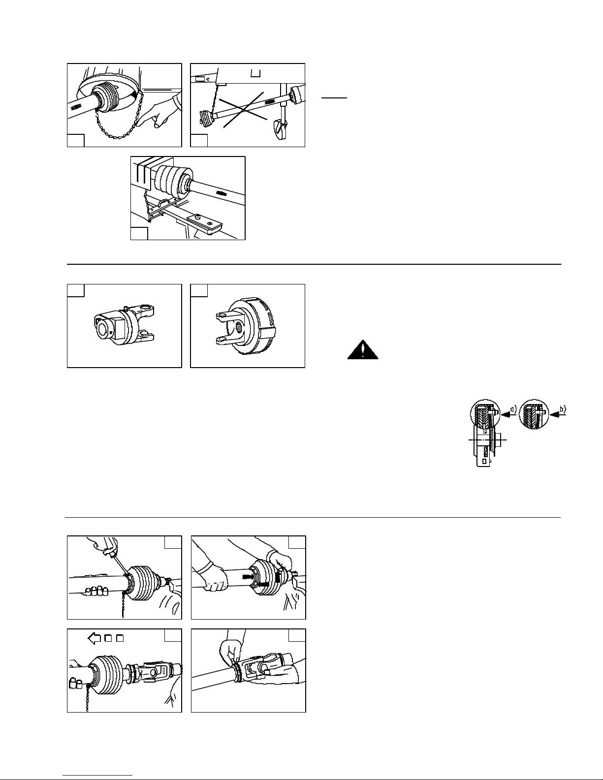
G1
G. Chains (Figs. G1 - G3)
NOTE: The chain is intended to prevent the shield
from rotating against non-moving parts and thereby
preventing shield damage. A properly installed chain
will increase the service life of the shield.
G2
1. Chains must be fitted so as to allow sufficient
articulation of the shaft in all working positions.
Care must be taken to be sure that chain does not
become entangled with drawbar hitch or other
restrictions during operation or transport of
machine.
G3
250968G
H1
250968H
H2
H. Shear bolt and friction clutches (Figs. H1 - H2)
1. Shear bolt clutches:
When the torque is exceeded, power flow is
interrupted due to the bolt shearing. The torque
is re-established by replacing the broken shear
bolt. Use only the bolt specified in the operator's
manual for replacement.
2. The PTO drive shaft must not be suspended from
the chain.
2. Friction clutches:
When overload occurs, the torque is limited and
transmitted constantly during the period of slipping. Short-duration torque peaks are limited.
Prior to first utilization and after long
periods out of use, check working of disk
clutch.
a. Tighten nuts until friction disks are released.
Rotate clutch fully.
b. Turn nuts fully back.
Now the clutch is ready
for use.
Fig. H2 shown.
Avoid extended and frequent slippage of overload
clutches.
J1
J3
250968J
J2
J. To dismantle guard: (Figs. J1 - J4)
1. Remove locking screw.
2. Align bearing tabs with cone pockets.
3. Remove half-guard.
4. Remove bearing ring.
J4
1-19
Page 20
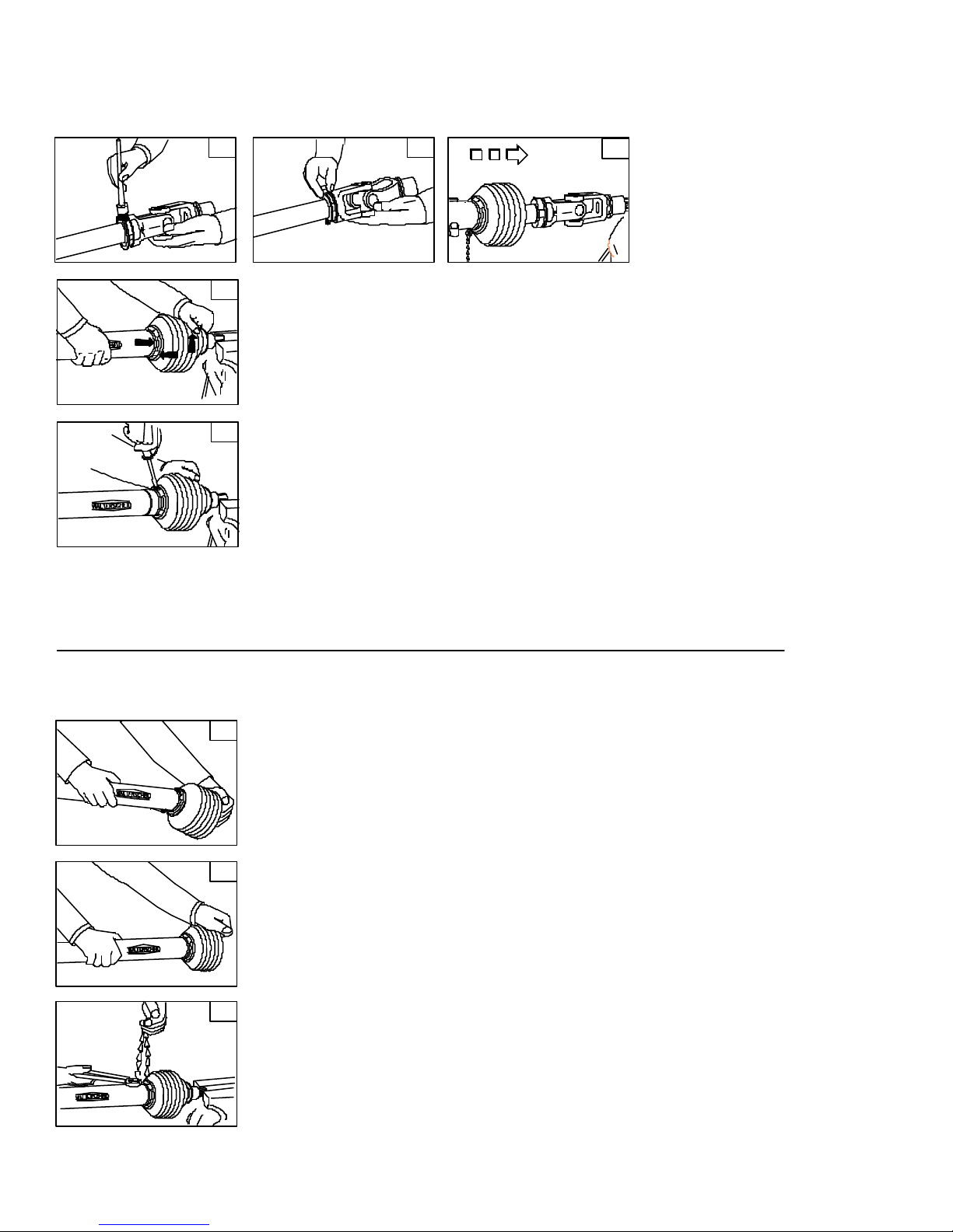
K1
K4
K2
K3
K. To assemble guard: (Figs. K1 - K5)
1. Grease yoke groove and inner profile tube.
2. Fit bearing ring in groove with recesses facing
profile tube.
250968K
K5
L1
L2
3. Slip on half-guard.
4. Turn cone until it engaes correctly.
5. Install locking screw.
L. To assemble cone:
1. Dismantle guard (Figs. J1 - J3). Remove old cone
(e.g. cut open with knife). Take off chain. Place
neck of new cone in hot water
(approx 80o C / 180o F) and pull onto bearing housing
(Fig. L1).
L3
250968L
2. Turn guard cone into assembly position (Fig. L2).
Further assembly instructions for guard
(Figs. K1 - K5).
3. Reconnect chain if required (Fig. L3).
1-20
Page 21
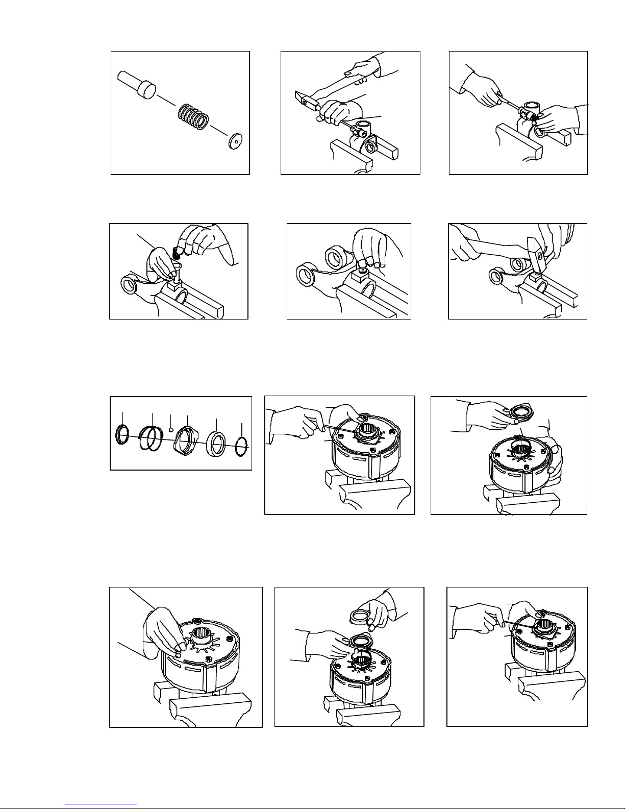
QUICK DISCONNECT PIN
Quick-disconnect
Pin
Compression
Spring
Washer
Using a drift punch and hammer, drive the pin towards the retaining washer to force the complete
assembly out. Clear the edges of the retaining washer bore to accept the new one by removing the
deformed metal from the last peening operation to hold the washer in place.
Insert quick-disconnect pin, compression spring and washer into
hole.
QUICK DISCONNECT DISASSEMBLY
1
2
*
1 Compression Spring
2 Ball
3 Lock collar
4 Back-up ring
5 Snap ring
* Back-up ring
* (For some clutch types, place
additional back-up ringfirst).
3
4
5
Compress lock collar (#3) and
remove snap ring (#5).
QUICK DISCONNECT ASSEMBLY
Holding the washer in place,
peen the edges of the bore
seat to retain the washer,
spring and pin.
Remove back-up ring, lock collar, compression spring and balls.
Insert balls. Place compression spring, lock collar and back-up ring
onto the hub.
1-21
Remove back-up ring, lock
collar, compression spring and
balls.
250959
Page 22
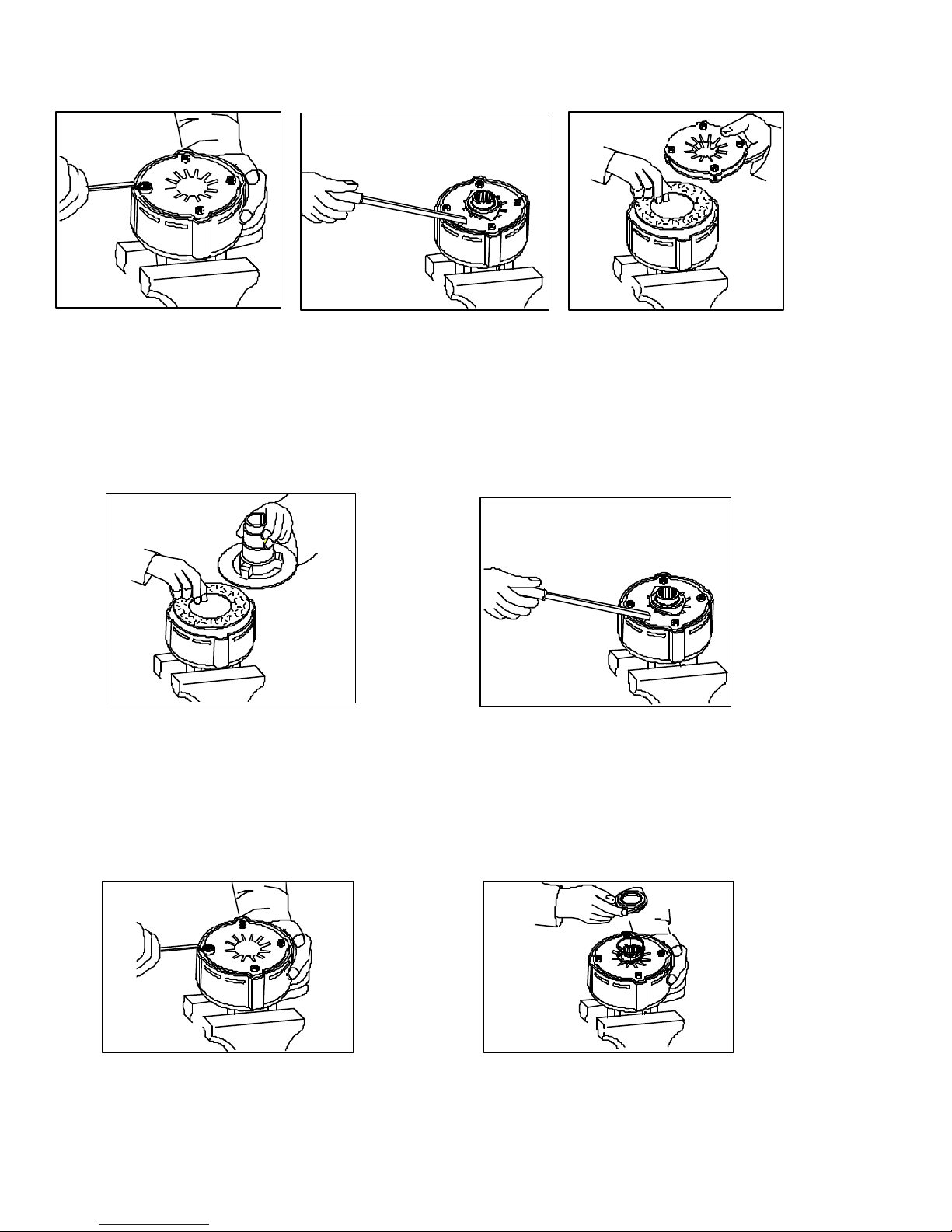
CLUTCH DISASSEMBLY
Tighten the four hex nuts (12)
uniformly until the clutch pack
and hub are loose.
Use special tool 9002007 to bend
all four retaining lugs back on the
edge of the clutch housing.
CLUTCH ASSEMBLY
Place hub and friction disks into the clutch
housing. Note that items #8 & 9 are only used
in the four plate clutch. Next compress the
Belleville spring(s) to the pressure plate by
tightening the four hex nuts and placing them
into the clutch housing as illustrated.
Remove the thrust plate with
Belleville springs to get at the
friction disks, drive plates and
hub for inspection and service.
Use special tool #9002007 to bend the retaining lugs inward over the Belleville spring edges
to secure the springs when you back the four
hex nuts off. (Note: Wide lugs for one (1)
Belleville spring, narrow lugs for two (2)
Belleville springs)
With the lugs in place loosen the four hex nuts
completely to the end of the threaded studs.
250959
Replace the quick-disconnect assembly.
1-22
Page 23
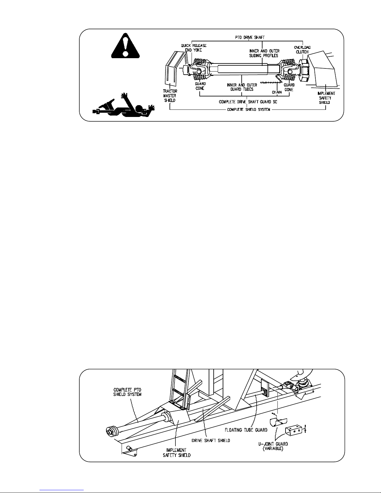
DRIVELINE SAFETY PRECAUTIONS
- DANGER ZONE -
Attention!
Become Alert!
250968A
.
Read and understand the equipment Operator's
manual.
Follow all safety messages in the Operator's Manual
.
and safety signs on the equipment.
Do not allow children near equipment that is
.
running or engaged.
Recognize and accommodate any physical
.
limitations of elderly and handicapped persons
assisting with farmwork.
Keep all guards and shields in good condition and
.
properly installed at all times.
Avoid personal attire such as loose fitting clothing,
.
shoestrings, drawstrings, pants cuffs, long hair,
etc. that can become entangled in a rotating driveline.
.
Disengage the PTO, stop the tractor engine, and
remove key from ignition before making inspections, or performing maintenance and repairs.
.
Inspect the driveline, quick disconnect, overload
shear-bolt limiter or clutch, and shielding often.
Repair immediately. Use replacement parts and
attaching hardware equivalent to the original
equipment. Do not alter the original design of the
driveline.
.
Avoid excessively long hardware or exposed and
protruding parts which can snag and cause
entanglement.
.
Lubricate the driveline as recommended in the
Operator's manual.
.
Keep hoses, wiring, ropes, etc from dangling too
close to the driveline.
.
Install driveline and shields according to recommended lengths and attaching methods with
recommended hardware. The driveline shield
should rotate independently a full rotation and
telescope freely. The retaining chain must be
secured to the tractor or equipment as recommended.
.
Attach offset drawbar hitch end in the down position
and use a recommended hitch pin with a low head
so that no interference occurs with driveline during
operation on uneven or terraced terrain.
.
Operate driveline within the recommended speed
and torque limits.
.
Be careful not to hit the driveline with tractor tires
when turning.
• 04-16-01
250968A
1-23
Page 24

TIRE REFERENCE
FOR QUESTIONS REGARDING NEW TIRE WARRANTY, PLEASE CONTACT YOUR
LOCAL ORIGINAL EQUIPMENT TIRE DEALER. USED TIRES CARRY NO WARRANTY.
FOLLOWING ARE PHONE NUMBERS AND WEBSITES FOR YOUR CONVENIENCE:
Firestone www.firestoneag.com
800-897-3364
Goodyear www.goodyear.com
1-800-GOODYEAR
Titan
www.titan-intl.com
Phone 800-USA-BEAR
Fax 515-265-9301
Carlisle
Trelleborg www.trelleborg.com
NOTES
www.carlisletire.com
Phone 800-260-7959
Fax 800-352-0075
Phone 866-633-8473
Fax 330-877-4876
• 04-01-02
1-24
Page 25

SECTION II - PARTS
PAGE
PTO ASSEMBLY ...................................... 2-2
PTO CLUTCH........................................... 2-3
UNDERCARRIAGE ................................... 2-4
AUGER..................................................... 2-6
BOX & ELECTRICAL................................ 2-8
DECALS .................................................. 2-10
SIDE BOARDS ....................................... 2-11
LOWER AUGER AND DRIVELINE ......... 2-12
DRIVE LINE U-JOINT ASSEMBLY ......... 2-13
HUB ........................................................ 2-14
120 - 154 ADJUSTABLE AXLE .............. 2-16
• 04-01-02/122904-2
45O GEAR BOX...................................... 2-18
14" AUGER CYLINDER.......................... 2-19
36" FLOW CONTROL DOOR CYLINDER.. 2-19
HYDRAULIC PTO DRIVE
SCALE
ELECTRICAL ............................................2-23
•
HYDRAULIC DRIVE KIT (OPTIONAL) .......2-24
(OPTIONAL) ..............................................
(OPTIONAL) ......
2-1
2-20
2-22
Page 26
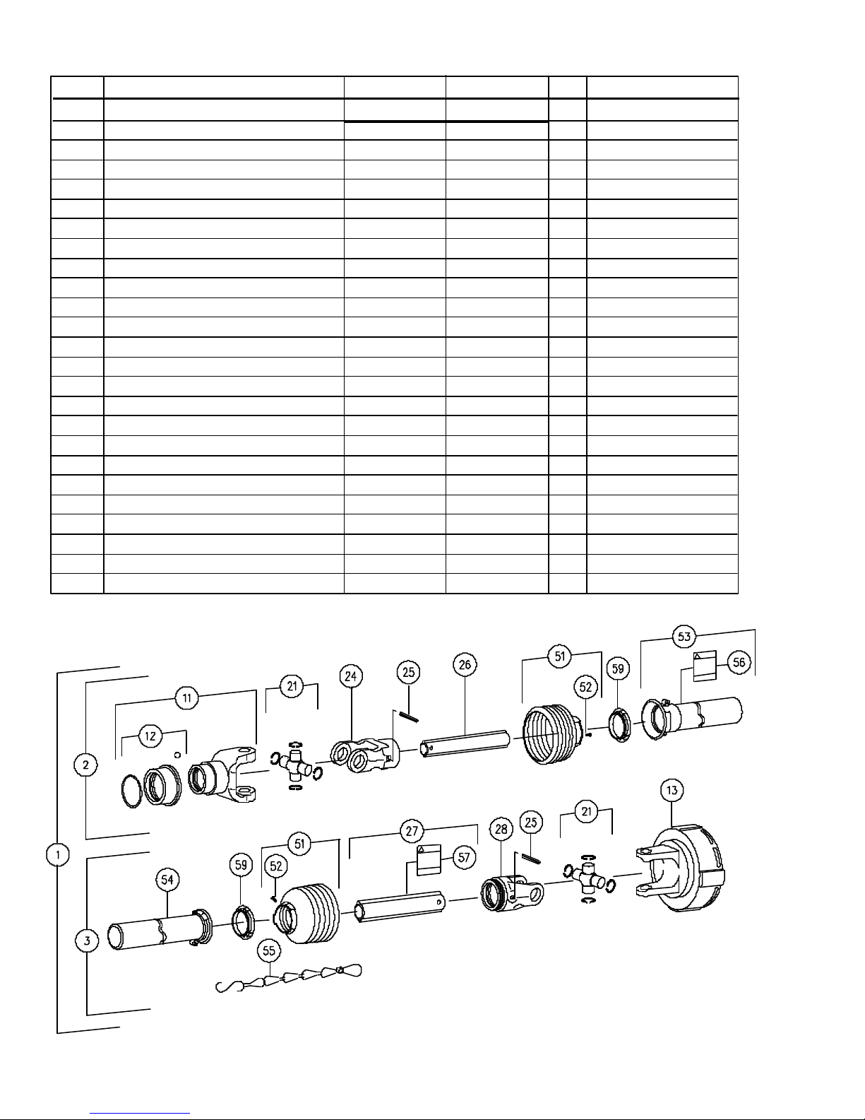
PTO ASSEMBLY
ITEM DESCRIPTION PART NO. PART NO. QTY NOTES
672 674
1 PTO Shaft w/Shielding 94866 94868 1 1 3/4-20 Spline
PTO Shaft w/Shielding 94867 95214 1 1 3/8-21 Spline
2 Front Half PTO 94835 94841 1 1 3/4-20 Spline
Front Half PTO 94826 95215 1 1 3/8-21 Spline
3 Rear Half PTO 94827 94842 1
11 End Yoke 92379 93855 1 1 3/4-20 Spline
End Yoke 92361 95216 1 1 3/8-21 Spline
12 Quick Disconnect Kit 93856 > 1 1 3/4-20 Spline
•
12 Quick Disconnect Kit 95217 > 1 1 3/8-21 Spline
13 Friction Clutch Complete 92925 9000964 1 4-Plate Clutch
•
21 Cross & Bearing Kit 92364 93857 2
24 Front Inboard Yoke 92366 93858 1
25 Spring Pin 92367 93859 2
26 Inner Profile 94828 94828 1
•
27 Outer Profile 94829 92369 1 36" / 46 1/4"
28 Rear Inboard Yoke 92370 93862 1
51 Shield Cone-Black 92371 93863 2
52 Screw 92372 92372 2
53 Outer Shield Tube w/Cap 94839 > 1 Replaces 94830
54 Inner Shield Tube w/Cap 94840 > 1 Replaces 94831
55 Safety Chain 92374 > 1
56 Danger Decal - Shield 92377 > 1
57 Danger Decal - Steel 92378 > 1
59 Bearing Ring 92373 > 2
250928
• 04-01-02
2-2
Page 27
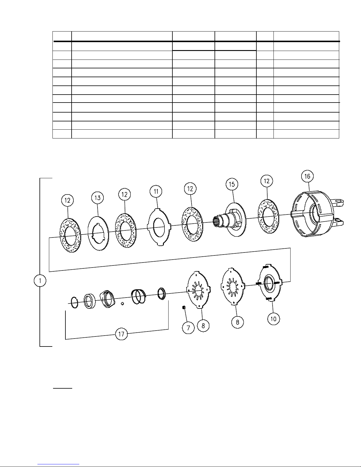
PTO CLUTCH
ITEM DESCRIPTION PART NO. PART NO. QTY, NOTES
672 674
1 Clutch Complete 92925 94838 1 Items 7 Thru 17
7 Nut, M8 DIN 6330 Hex 92386 > 4
•
8 Belleville Spring (Red dot) 93815 > 2 Repl. 92915 (White dot)
10 Thrust Plate 92384 > 1
11 Drive Plate 92850 > 1
12 Clutch Lining 92382 > 4
13 Drive Plate 92851 > 1
15 Hub 94982 94982 1 1 3/8-21 Spline
16 Clutch Housing 92926 93805 1
17 Quick Disconnect Flange Kit 92393 > 1
NOTE: The clutch is preset at the factory and should not require adjustment. See Section
1 for specific clutch information.
• 05-19-99
250952
2-3
Page 28
PAINT GALLON SPRAY
Black 9000913 9000533
Green 9002594 9001791
Red 9002593 9002197
Primer, Gray 9000914 9000592
Primer, White 9002595 NA
Graphite 95201 NA
265915
250936
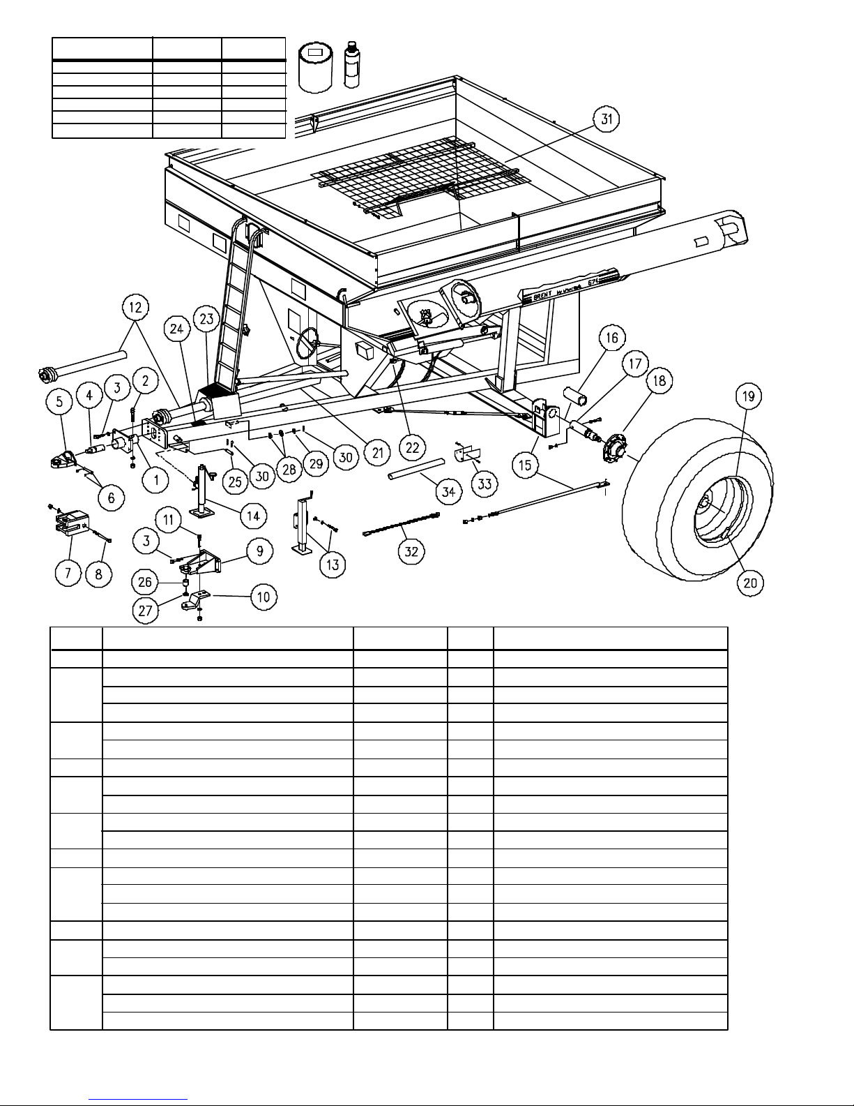
ITEM DESCRIPTION PART NO. QTY. NOTES
1 Scale Hitch Bushing 250487B 1 Scale Unit Only
2 Capscrew, 1-8 UNC x 6 9390-195 1 Bushing to Frame Tube
Lockwasher, 1" 9404-041 1
Nut, 1-8 UNC 9394-020 1
3 Capscrew, 3/4-10 x 2 1/4 Gr 8 9390-146 4 Bushing to Frame Plate
Lockwasher, 3/4 9404-033 4
4 Weigh Bar -- 2 1/2" Dia. 92400 1 Scale Unit Only
5 Scale Hitch, Single Tang - 1 1/2" 250494* 1
Scale Hitch, Single Tang - 2" 265637* 1
S/N 674-B1651099 / 672-B16490099 & Lower
S/N 674-B1651100 / 672-B16490100 & Higher
6 Pin, 1 x 4 1/4" 250844 1 Replaces 250490 As
Snap Ring 91192 2 Replaces 94142 Set
7 Scale Hitch, Clevis 200004B 1 Scale Unit Only
8 Capscrew, 1-8 UNC x 7 9390-197 1
Lockwasher, 1" 9404-041 1
Nut, 1-8 UNC 9394-020 1
9 Hitch 250699* 1 Incl. 250636 & Items 26 - Repl. 250486
10 Hammer Strap Assembly (Option) 265639 1 Incl. 265638 & Items 11 - Repl. 250499
Decal, Hammer Strap 9001663 1
•
11 Capscrew, 3/4-10 UNC x 3 9390-149 2
Lockwasher, 3/4 9404-033 2
Nut, 3/4-10 UNC 9394-016 2
2-4
• 12-19-01
Page 29

MODEL 672 & 674 - UNDERCARRIAGE
ITEM DESCRIPTION PART NO. QTY. NOTES
12 PTO Page 2-2
13 Jack Assembly, Flange Mount 232311 1 Incl. 250022 & Fasteners
Capscrew, 5/8 UNC x 1-3/4 9390-123 4
Lockwasher, 5/8 9404-029 4
Nut, 5/8 UNC Hex 9394-014 4
14 Jack, Swivel Mount - Top Wind 9003299 1 Repl. 9992B
15 Axle, 120" Rigid 200084 1
Axle, 144" Rigid 200240 1 Repl. 200085
Axle, 150" Rigid 200088 1 Req'd. for Duals
Axle, Adjustable 1 Pages 2-16 & 2-17
Brace, Axle (63 1/2" Overall) 200172 2 144 & 150" Rigid Axle only
Brace, Axle (58-1/2" Overall) 200173 2 Used with Adjustable Axle
16 Spindle Bushing, 4 1/2 x 3 3/4 x 9 1/4" 200025 2 Duals with Scale, 4 1/2" ID Axle
17
S/N 674-B1651099 & 672-B16490099 & Lower
Spindle, 2 7/8" Dia. 200176 2
Spindle, 2 7/8" Dia. - Scale 92442 2
Spindle, 4 1/2" Dia. 200177 2 For Duals
Spindle, 3 3/4" Dia. - Scale 92443 2 For Duals
17
S/N 674-B1651100& 672-B16490100 & Higher
Spindle Ass'y, 3 3/4" Dia. 250605 2 Incl. 250601, Nut,Washer,CPin
Spindle, 3 3/4" Dia. - Scale 9002009 2 Optional - See Page 2-20
18 Hub Page 2-14
19 Wheel, W10-20 x 26 - 11.25" BC 92413 2
Wheel, W10-25 x 26 92414 2
Wheel, W10-21 x 32 92415 2
Wheel, W10-27 x 32 95960 2 Repl. 11075
Wheel, W10-20 x 34 92747 2
19 Wheel, W10-21 x 32 - 13.187" BC 92416 2
Wheel, W10-27 x 32 92417 2
19 Wheel, 16 x 38 - 13.187" BC 12397WO 4
Wheel, 18 x 38 12398WO 4
Wheel, 16 x 42 12399WO 4
Wheel, 13 x 46 12967WO 4
19 Wheel, 16 x 38 - 13.187" BC 15304 4
•
Wheel, 18 x 38 15305 4
Wheel, 16 x 42 14561 4
Wheel, 13 x 46 15303 4
20 Valve Stem 93300 2
21 PTO Shield 250798B 1 48 1/2" Lg.
22 U-Joint, 3/4" 92405 1
23 Pad, PTO Shield 9001496 1
24 Pad, Runner 9001497 2
25 Pin, Safety Chain, 1 1/4 x 3 3/4" 250151 1
26 Adapter Bushing 9001917 1 Optional for 1 1/2" Hitch Pin
Adapter Bushing 9002130 1 Optional for 1 3/4" Hitch Pin
27 Spacer Washer, .180 x 1.52 x 3.00 250392 1 1 1/2" Hitch Pin - Standard
28 Spacer Washer, .180 x 1.78 x 3.25 250393 1 1 3/4" Hitch Pin - Optional
Spacer Washer, .180 x 2.019 x 3.50 265389 1 2" Hitch Pin - Optional
29 Flatwasher 9405-118 1
30 Hair Pin Cotter 92424 1
31 Screen Weldment 250501 1
32 Safety Chain 9003265 1
33 Guard, PTO Shaft 251279B 1
34 Guard Pipe, PTO 251285 1 42"
• 12-19-01
2-5
S/N 674-B1651099 & 672-B16490099 & Lower
S/N 674-B1651100& 672-B16490100 & Higher
For Dual Wheel
For Dual Wheel
For Dual Wheel
For Dual Wheel
For Dual Wheel
For Dual Wheel
For Dual Wheel
For Dual Wheel
* Specify Color as R for Red or G for Green
Serial No.
B19380099
& Lower
3/4" Studs
Begin Ser. #
B19380100
7/8" Studs
See Hub also
Page 30
250937
• 06-30-00
2-6
Page 31

MODEL 672 & 674 - AUGER
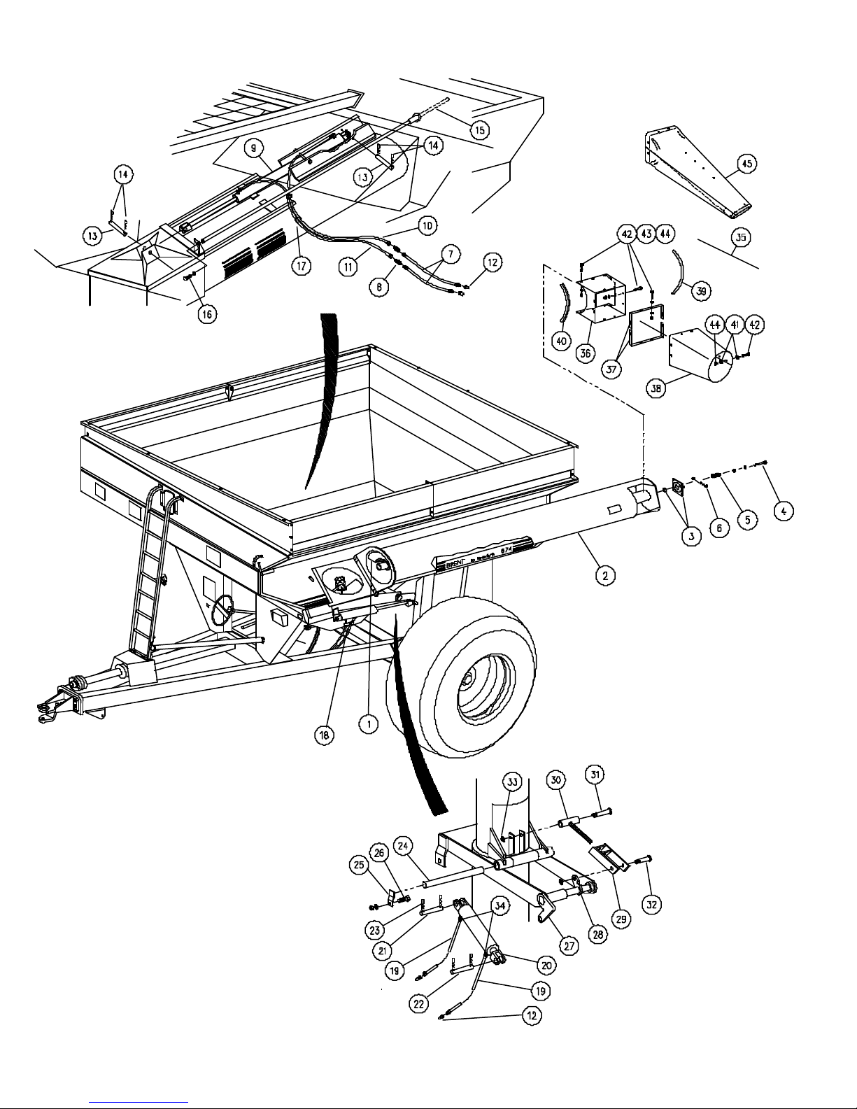
ITEM DESCRIPTION PART NO. PART NO. QTY. NOTES
672
1 Upper Auger 250416 265130 1
2 Upper Auger Housing ×250652* 250013* 1 ×Includes Items 4 & 5A
3 Flange Bearing, 1-1/2 4-Hole 92406 > 1
Washer 9001197 > AR 2 x 1.554 x .134
4 Capscrew, 1/2-13 UNC x 5-1/2 9390-114 > 4
Locknut, 1/2-13 UNC 94981 > 4
5 Spring, Auger, 1 x 3" 92407 > 4
5A Spring, Auger, 1 x 4" 9001812 > 4
6 Machine Screw, 5/16-18 UNC x 2 95572 > 1 Rd Slot Hd-Stub Shaft Retainer
Nut, 5/16-18 UNC 9394-004 > 1
7 Hydraulic Hose, 228" O-Ring Ftg. 9002215 > 2
8 Bulkhead Fitting 95192 > 2
9 Hydraulic Cylinder, 36" Page 2-16 > 1
10 Hydraulic Hose, 16" 95141 > 1
11 Hydraulic Hose, 40" Lg. 95003 > 1
12 Disconnect Male Tip - SAE O -Ring 91383 > 4
13 Pin, Inside Cylinder, 1 x 4" 250104 > 2/1
Pin, Inside Cylinder, 1 x 5 1/2" 92428 0/1
14 Hair Pin, #6 92424 > 4
15 Rod, Door Indicator 250590 > 1
16 Capscrew, 1/2 UNC x 1 9390-099 > 1
Lockwasher, 1/2 9404-025 > 1
17 Tie Strap, 15 1/2" 9000107 > 6
18 Hose Bracket 7-0043B > 1
19 Hydraulic Hose, 216" O-Ring Ftg. 9002212 > 2
20 Hydraulic Cylinder, 14" Page 2-16 > 1
•
21 Upper Pin, Cylinder, 1 x 2-7/8 233760 92425 1 1 x 3"
22 Lower Pin, Cylinder, 1 x 3-1/2 804572 92425 1 1 x 3"
•
23 Hair Pin, #6 92424 > 8
24 Hinge Pin 200012 250014 1 1 x 16 1/2 1 x 20-7/8
25 Keeper, Shaft 7-0328 > 1
26 Capscrew, 1/2 UNC x 1 9390-099 > 1
Lockwasher, 1/2 9404-025 > 1
Nut, 1/2-13 UNC Hex 9394-010 > 1
27 Arm, Cylinder 200033 250474 1
28 Rockshaft & Crank Ass'y 200034 250016 1
29 Tee Bar, Yoke End 200028B > 1
30 T-Bar, Threaded 200013 > 1
31 Pin, Upper T-Bar 250106 > 1
32 Pin, Lower T-Bar 250105 > 1
33 Nut, 1-8 Jam 94740 > 2
34 Restrictor, .030" 95193 > 2 Repl. 9000288
35 Chute Kit, Incl. Items 36 thru 44 250317 265318
36 Shroud, Outlet 250457B 265182B 1
37 Strap 250432B 250428B 2
38 Chute 9001437 9001438 1
39 Trim Lock 9000787-159000787-24 1
•
•
40 Trim Lock 92444-17 92444-30 1
41 Fender Washer, 1/4 x 2 94763 > 6
42 Capscrew, 1/4-20 UNC x 1 9390-005 > 20
43 Fender Washer 9405-066 > 25
44 Locknut, 1/4-20 UNC Centerlock 9936 > 20
45 Adjustable Chute 9001780 > 1 Option
• 12-19-01
674
672-B1681099 / 674-B1682099 & Lower
672-B1681100 / 674-B1682100 & Higher
Repl. 95140 (pipe thd), Requires12
Repl. 93474 (pipe thd) - For 7 &19
Top Pin, 2 1/2 x 36" Cylinder only
Repl. 92426 (pipe thd), Requires12
* Specify Color as R for Red or G for Green
2-7
Page 32
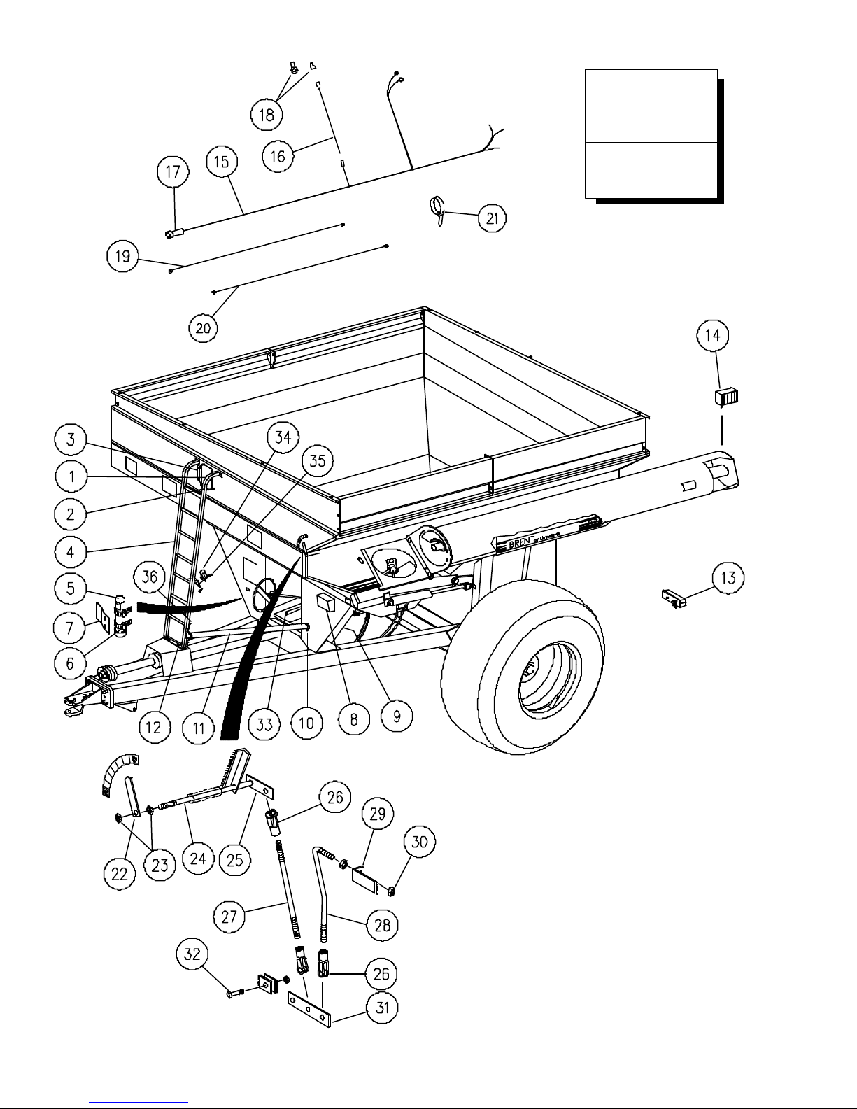
Electrical System
Items 13 Thru 21
Serial #B19380099
& Lower
Begin Serial No.
B19380100
See Page 2-23
250938
2-8
• 12-19-01
Page 33

MODEL 672 & 674 - BOX & ELECTRICAL
ITEM DESCRIPTION PART NO. QTY. NOTES
1 Window 92403 2 Kit 220512 Incl. Items 1-3
2 Window Molding 250431 2
•
3 Bracket, Window Retaining 250461B 2
Capscrew, 1/4-20 UNC x 1 9390-005 4
Locknut, 1/4-20 UNC 9936 4
•
4 Ladder 250473B 1
5 Tube, Manual 9000943 1
6 Clamp, 3-1/2" 9001926 2
7 Bracket 250229 1
8 Scale Indicator Box (EZ-150) 9001184 1 Standard Scale Kit
Scale Indicator Box (EZ-210) 9001338 1 Scale Kit W/Printer Option
9 Scale J Box 92447 1
10 Hose Clamp, 3" 9000392 2
11 Hose Tube, Plastic 250463 1 52 1/2" Lg.
12 Bracket, Ladder 250480B 1
Capscrew, 3/8-16 UNC x 3/4 9390-053 2
Nut, 3/8-16 UNC Centerlock 9928 2
13 Light, Tail & Turn 9001065 2
Gasket, Mounting 9001977 1
•
14 Auger Light 9001155 1 Kit 233134 Replaces 9001064
15 Wiring Harness 92448 1
16 Wiring Harness - Auger 9000375 1
17 Electrical Coupler, Front 92450 1
18 Connector, Male 9001660 1
•
19 Scale Power Cord 92452 1
20 Scale Cab Extension Cord 92453 1
21 Cable Tie, 7" 91217 7
22 Needle, Indicator 200116 1
23 Nut, 3/8-16 UNC Jam 9395-006 2
24 Rod, 3/8 x 62 3/4" 250322 1 672
25 Bracket 9-2168 1
26 Yoke w/Pin, 1/4-28 95183 3
27 Rod, 1-4/-28 x 12 3/8 265191 1
28 Rod, 1/4-28 x 9 1/4 250467 1
29 Bracket, Pivot 250500 1
30 Nut, 1/4-28 Hex 9394-001 2
31 Linkage, Indicator 265192 1
32 Capscrew, 3/8-16 UNC x 1 1/2 9390-057 1
33 Grommet, 15/16" Dia. 9001816 5
34 Connector Holder 9001968 1
35 Capscrew, 1/4-20 UNC x 3/4 9390-003 2
36 Cap Plug, Hose Bracket 9001803 1
• 06-30-00
Connector, 1/2" Eyelet 9002127
Rod, 3/8 x 66 3/4" 250465 1 674
Pin, Clevis 95184 3
Nut, 3/8-16 UNC Centerlock 9928 1
Lockwasher, 1/4 9404-017 2
Nut, 1/4-20 UNC 9394-002 2
2-9
Page 34
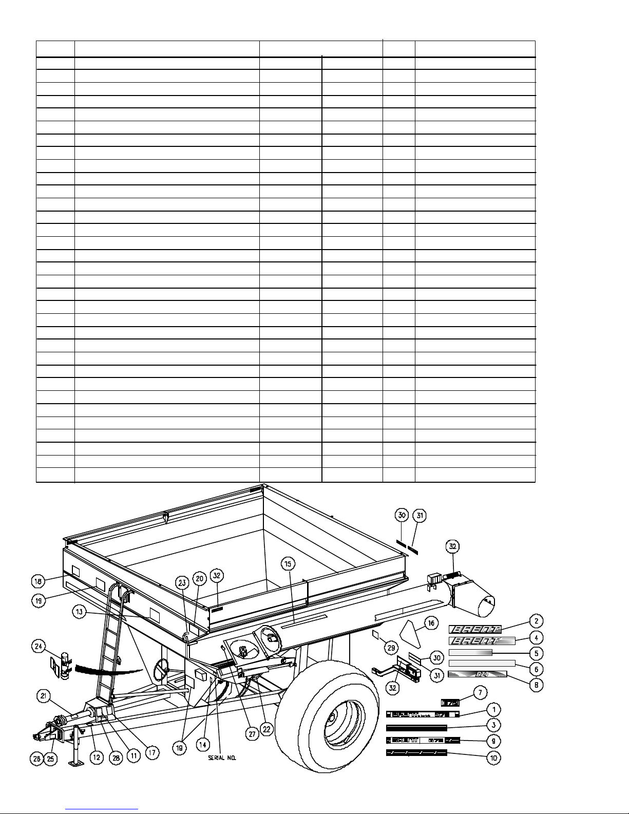
MODEL 672 & 674 - DECALS
ITEM DESCRIPTION PART NO. QTY. NOTES
672 674
1 Decal, Brent By Unverferth 92553 - 3
2 Decal, Brent 9004234 3 Prior to Serial #B21780100
•
3 Decal, Stripes Tricolored 92555 - 5
•
4 Decal, Brent Fading Stripe - 9004214 2 Prior to Serial #B21780100
•
5 Decal, Fading Stripe - 9004216 3 Prior to Serial #B21780100
•
6 Decal, Stripe - 9004215 2 Prior to Serial #B21780100
7 Decal, 672 9001902 - 3 Repl. 92906 / 93800
8 Decal, 674 9004253 3
•
9 Decal, Brent By Unverferth 250897 - 3 Repl. 9002463-672
10 Decal, Fade Stripes 9002464 - 5
11 Decal, Warning to Avoid Injury 9003475 > 1 Repl. 91301
12 Decal, Caution Do Not Play 9003476 > 1 Repl. 9083
13 Decal, Flow Control Gate 9003477 > 1 Repl. 91410
14 Decal, FEMA 91605 > 1
•
15 Decal, Flow Control 3" x 38" 92563 > 1
16 SMV Metal Sign 9829 > 1
17 Decal, Caution To Avoid Injury 91302 > 1
18 Decal, Danger Just For Kids 9003478 > 1 Repl. 95209
19 Decal, Danger, Drive Shaft 95046 > 3 Repl. 91300
20 Decal, Danger Electrical Lines 9003474 > 1 Repl. 91303
21 Decal, Important Double U-Joint 92561 > 1
22 Decal, Hydraulic Oil Pressure 95445 > 1
23 Decal, Auger Lock, 672 / 674 9001493 9001494 1
24 Decal, Manual 9000917 > 1
25 Decal, Hitch Torque 9001709 > 1
26 Decal, Hammerstrap 9001663 > 1 Option
27 Decal, Reflective Checker Tape 265384 > 1
28 Decal, Tongue Drop 94094 > 1
•
29 Decal, Light Placement 9003518 > 1
30 Fluorescent Strip, Red-Orange 9003125 > 2 2 x 9"
31 Red Reflector 9003126 > 2 2 x 9"
32 Amber Reflector 9003127 > 7 2 x 9"
250939
• 09-22-03/122904-2
2-10
Page 35
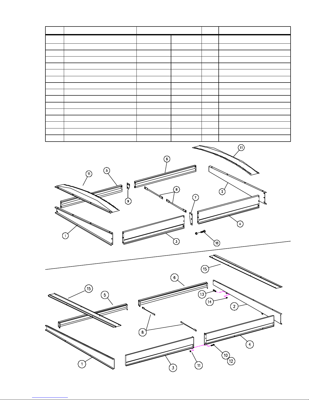
MODEL 672 & 674 - SIDE BOARDS
ITEM DESCRIPTION PART NO. QTY. NOTES
Serial #B1649100 Beginning Serial
Thru #B18260999 #B18590100
1 Front Board 200215B 250870B 1 18" to 5" Tall
2 Rear Board 200216B 250871B 1 18" to 5" Tall
3 Left Front Side Board 250453B 250874B 1 18" Tall
4 Left Rear Side Board 250454B 250875B 1 18" Tall
5 Right Front Side Board 250451B 234193B 1 12"
6 Right Rear Side Board 250452B 234194B 1 12"
7 Side Board Brace 200220B - 1/8 Side Board Support 220032B > 1/2 39 7/8" Lg.
9 Side Board Brace 200055B - 1/10 Flange Screw, 3/8-16 x 3/4 95585 > 15/21
11 Flange Nut, 3/8-16 91263 > 15/25
12 Flange Screw, 3/8-16 x 1 - 91262 -/4
13 Capscrew, 3/8-16 x 3 1/2 - 9390-065 -/4
14 Locknut, 3/8-16 - 9928 -/4
15 End Cap, Tarp Section 4 > 1
• 01-22-01
250920
2-11
Page 36
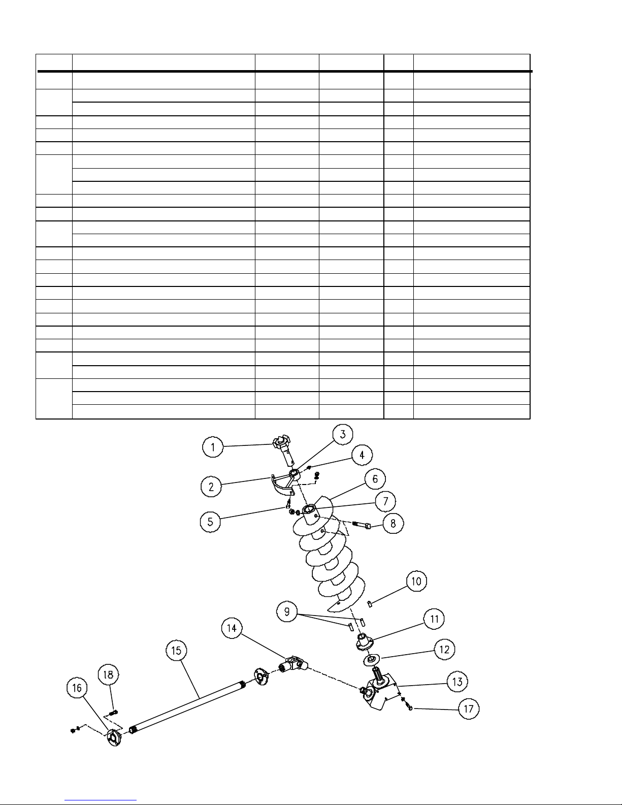
LOWER AUGER AND DRIVELINE
ITEM DESCRIPTION PART NO. PART NO.QTY. NOTES
672 674
1 Drive Dog/Missle Shaft 250424 265125 1
4-Tooth 3-Tooth
2 Hanger Bushing Assembly 250119 265132 1 2" I.D.
3 Bushing, 2" / 2 1/2" I.D. 95315 9001198 1
4 Zerk, 90
5 Capscrew, 3/8 UNC x 1-1/4 9390-056 > 3
Lockwasher, 3/8 9404-021 > 3
Nut, 3/8 UNC Hex 9394-006 > 3
6 Lower Auger 250415 250273 1
7 Bushing - 265138 1
8 Capscrew,
Locknut,
9 Lower Drive Dog 250005 > 2 1 x 4
10 Pin, Auger Height 250004 > 1 1 x 2
11 Lower Drive Bushing 250003 250018 1
12 Gear Box Dust Cover 92805 > 1
13 45o Gear Box Page 2-15 > 1
14 U-Joint Page 2-13 > 1 1 3/8-21 to 1 3/8-16
15 Drive Shaft 250021 > 1 1 3/8 x 98" Lg.
16 Bearing, Flangette - 1-3/8" 92916 > 2
17 Capscrew, 1/2-13 UNC x 1 1/4 9390-100 > 8
Lockwasher, 1/2 9404-025 > 8
18 Capscrew, 3/8-16 UNC x 1 9390-055 > 6
•
Lockwasher, 3/8 9404-021 > 6
Nut, 3/8-16 UNC 9394-006 > 6
o
1/2-13 x 4 / 5/8-11 x 6
1/2-13 / 5/8-11
9000875 > 1
9390-111 9390-136 2
9800 9801 2
250918
• 04-16-01
2-12
Page 37
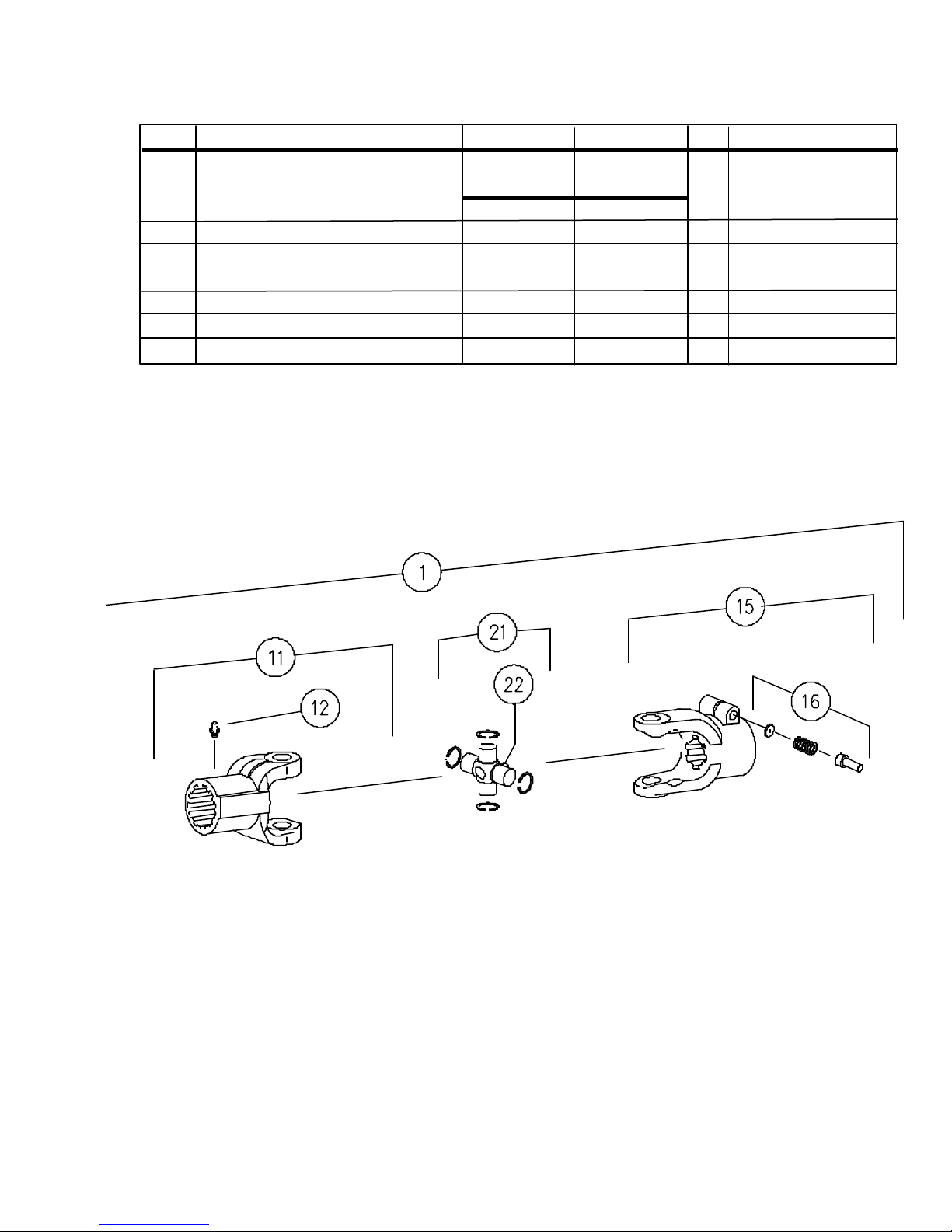
DRIVE LINE U-JOINT ASSEMBLY
ITEM DESCRIPTION PART NO. PART NO. QTY NOTES
672 674
1 Complete U-Joint Ass'y 92911 95012 1
11 Yoke 92910 95010 1
12 Grease Zerk, 1/4-28 UNF 91160 > 1
15 Yoke, 1-3/8-6 Spline 92909 95011 1
16 Quick-Disconnect Pin Kit 92362 > 1
21 Cross & Bearing Kit 92364 93857 1
22 Grease Zerk 92365 > 1
250953
2-13
Page 38
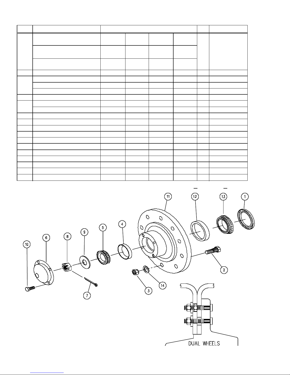
MODELS 672 & 674 HUB
ITEM DESCRIPTION PART NO.
Spindle 2 7/8" 4 1/2" 3 3/4" 3 3/4"
Bolt Circle 11.25" 13.187" 13.187" 13.187"
Serial No. & Lower Singles Duals Duals
674 #B1651099 / 672 #B1649099 Std, Scale Standard Scale
Beginning Ser. No. Singles Duals§ §
674 #B1651100 / 672 #B1649100 Std,Scale Std,Scale
QTY.
NOTES
Begin S/N B19380100
See Page 2-15
Complete Hub Assy 200036 200144 200079 200145* 1 Incl. 1-6 &10-13
1 Seal, 2 7/8" ID 92456 - - - 1 28464TA
Seal, 4 3/8" ID - 92455 - - 1 43605SA
Seal, 3 11/16" ID - - 92565 92565 1 37605SA
2 Stud, 3/4-16 x 3 / 3 1/2 Gr 8 94794 93333 94794 93333 10
3 Nut, 3/4-16 UNF,Flange / Hex 92458 93334 92458 93334 10
Nut, 3/4-16 UNF Jam - 9395-015 - 9395-015 5 Inner Dual Wheel
4 Outer Cup 92461 92462 > > 1 453A / HM212011
5 Outer Bearing Cone 92463 92464 > > 1 460 / HM212049
6 Hub Cap 92466 92465 > > 1
7 Cotter Key, 3/8 x 4" 9391-062 9391-091 > > 1
8 Nut 9393-024 92470 > > 1
9 Washer 92471 92472 > > 1
10 Capscrew, 5/16-18 x 1/2 9390-026 > > > 4
11 Hub 200037* 250329* 200039* 250329* 1 Incl. Items 2,4,12
12 Inner Cup 92475 92476 > > 1 33462 / HM218210
13 Inner Bearing Cone 92546 92545 > > 1 33275 / HM218248
14 Flatwasher - 93335 - 93335 10 Dual Wheels
* Specify Color as R for Red or G for Green
•
200144
• 12-19-01
2-14
Page 39
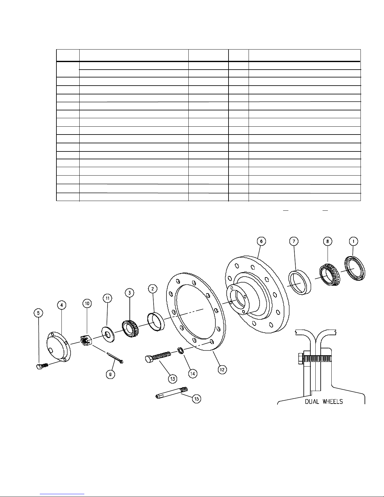
MODELS 672 & 674 - HUB - DUAL WHEELS
Begin Ser. No. B19380100
ITEM DESCRIPTION PART NO. QTY. NOTES
Hub Assembly--3 3/4" Spindle 266456*
1 Seal 92565 1 Ref. No. SA370605
2 Outer Cup 92462 1 HM212011
3 Outer Bearing Cone 92464 1 HM212049
4 Hub Cap 92465 1
5 Bolt 9390-026 4
6 Hub w/Cups & Studs 266455 1 Incl. Items 2 & 7
7 Inner Cup 92476 1 HM218210
8 Inner Bearing Cone 92545 1 HM218248
9 Cotter Key, 3/8 x 4 9391-090 1
10 Nut 92470 1
11 Washer 92472 1
12 Ring 14442 1
13 Bolt, 7/8-14 UNF x 4 97043 10
14 Lockwasher, 7/8 9404-037 10
15 Locator Bolt, 7/8-14 x 4 3/4 266459 1
* Specify Color as R for Red or G for Green
Includes Items 1 thru 8
266929
• 12-19-01
2-15
Page 40
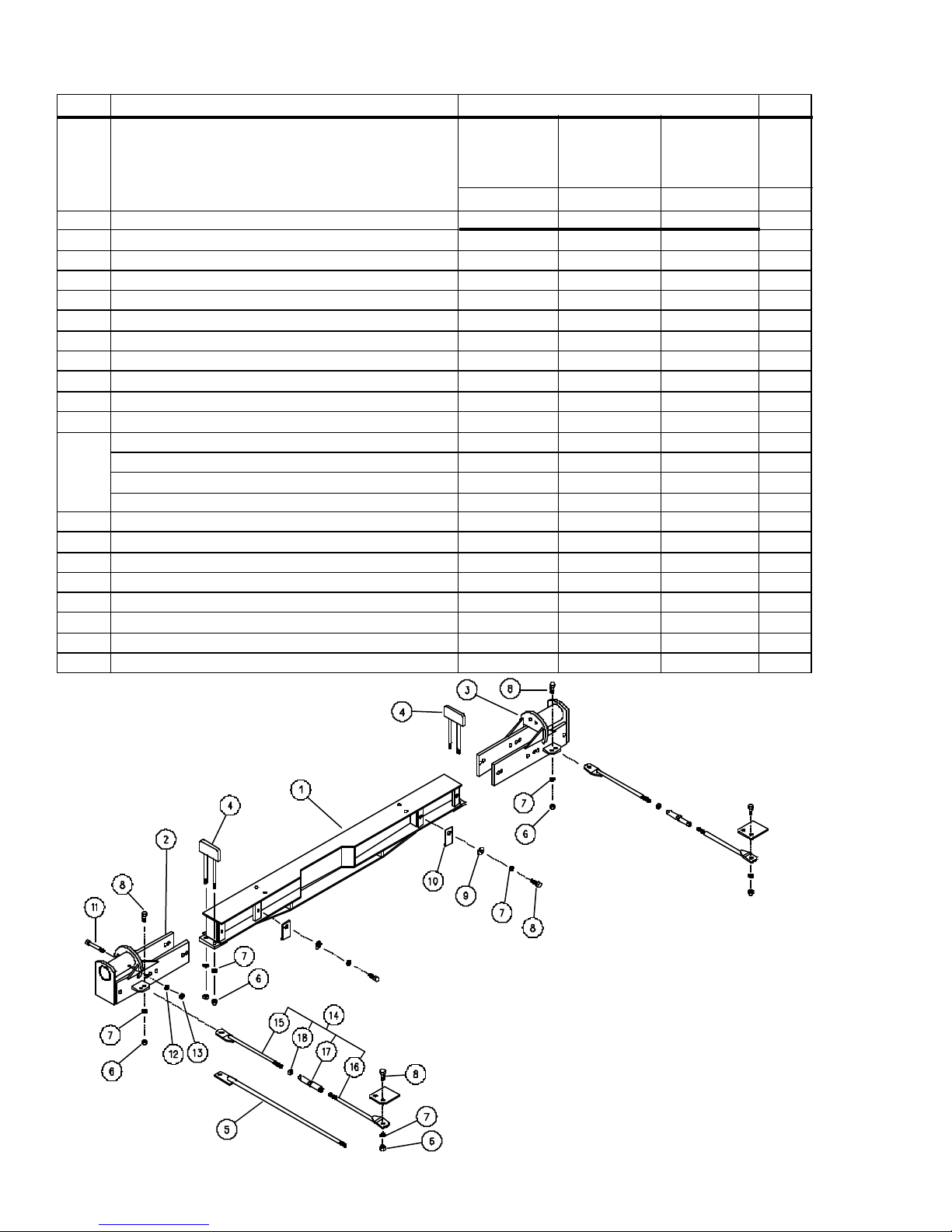
MODEL 672 & 674 ADJUSTABLE AXLE - 120"-150"
Trussed Style - For Replacement Only
ITEM DESCRIPTION PART NO. QTY.
674 S/N B1651099
& 672 - S/N B1649099
& Lower
- 4 1/2" Spindles -
Singles Duals Duals
120-144 120-150 120-150
Spindles 2 7/8" 4 1/2" 3 3/4"
Axle Assembly 200254 200090 200222 1
1 Axle Weldment 200107 200108 200108 1
•
2 RH Axle End 200102 200105 200223 1
3 LH Axle End 200103 200106 200224 1
4 Pull Down Weldment 200110 2
5 Axle Brace, 58 1/2" Overall 200173B > > AR
6 Nut, 1" Hex 9394-020 > > 6
7 Lockwasher, 1" 9404-041 > > 12
8 Bolt, 1-8 UNC x 3 9390-187 > > 10
9 Flatwasher, 1" 9405-117 > > 8
10 Axle Shim, 1/16 Thick 200112 > > VAR
Axle Shim, 1/8" Thick 200113 > > VAR
Axle Shim, 3/16" Thick 200114 > > VAR
Axle Shim, 1/4" Thick 200115 > > VAR
11 Capscrew, 5/8-11 UNC x 6 9390-136 > > 2
•
12 Lockwasher, 5/8 9404-029 > > 2
•
13 Nut, 5/8-11 UNC 9394-014 > > 2
•
14 Axle Brace Assembly, Incl. 15-18 250608B 2
•
15 Axle Brace, RH Thread 250636B 1
16 Axle Brace, LH Thread 250637B 1
17 Center Turnbuckle 62324 1
18 Jam Nut, 1 1/4-7 UNC 9395-041 1
Beginning S/N
674 - B1651100
& 672 - B1649100
- 3 3/4" Spindles -
250921
• 12-19-01
2-16
Page 41
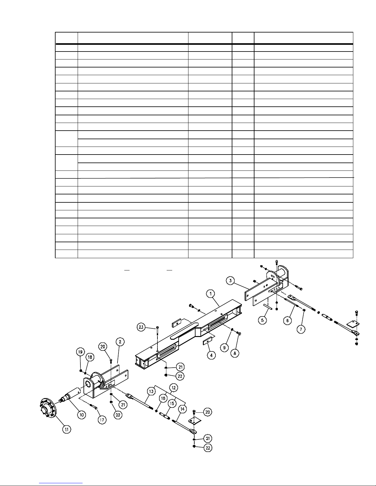
MODEL 672 & 674 ADJUSTABLE AXLE - 120" - 154"
ITEM DESCRIPTION PART NO. QTY. NOTES
Adjustable Axle Assembly 250641* 1 Includes 1-9 & 21-23 - Option
Adjustable Axle Assembly 250640 1 Includes Items 1 thru 9
1 Axle Weldment 265627 1
•
2 RH Axle End 250670 1
3 LH Axle End 250670 1
4 Clamp Plate 265539B 4
5 Axle Spacer Pipe 265634B 2
6 Axle Stud 265635B 2 10 1/8 Lg.
7 Locknut, 3/4-10 UNC Hex 96732 4
8 Capscrew, 1-8 UNC x 3 9390-187 4
9 Lockwasher, 1" 9404-041 4
10 Spindle Assembly, 3-3/4" 250605 2 Incl. 250601, Nut, Washer, C'Pin
Spindle, Scale, 3-3/4" 9002009 2 Optional - See Page 2-20
11 Hub 200079 2 See Page 2-14
12 Axle Brace Assembly 250666 1 Incl. Items 13-16, 20-22
Axle Brace Assembly 250608B 2 Includes Items 13 - 16
13 Axle Brace, RH Thread 250636B 2 23 1/8"
14 Axle Brace, LH Thread 250637B 2 22 1/8"
15 Center Turnbuckle 62324 2
16 Jam Nut, 1 1/4-7 UNC 9395-041 2
17 Capscrew, 5/8-11 UNC x 6 9390-136 2
18 Lockwasher, 5/8" 9404-029 2
19 Nut, 5/8-11 UNC 9394-014 2
20 Capscrew, 1-8 UNC x 2 1/2 9390-185 4
21 Lockwasher, 1" 9404-041 8
22 Nut, 1-8 UNC Hex 9394-020 8
23 Capscrew, 1-8 UNC x 3 9390-187 4
* Specify Color as R for Red or G for Green
NOTE: Items 5 & 6 must be used
when axle is set to 144" or greater.
250964
• 09-04-01
2-17
Page 42
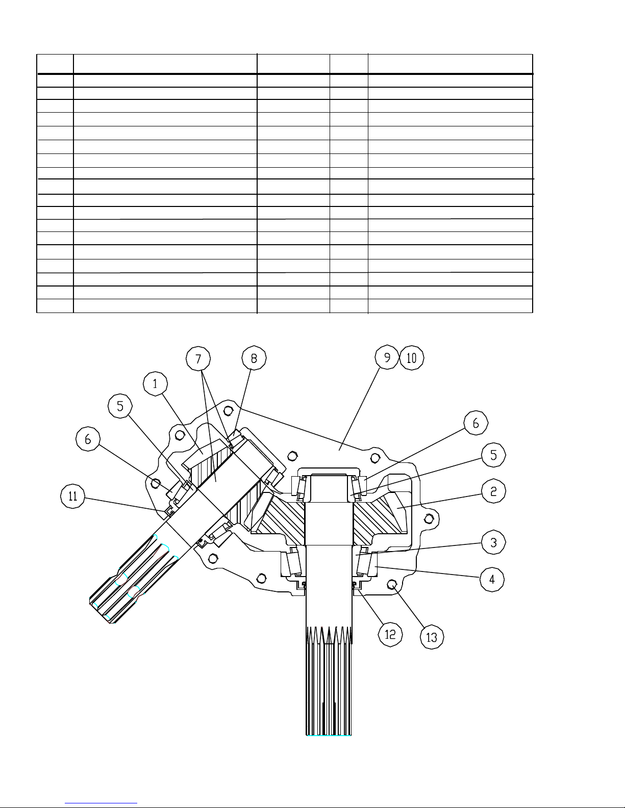
45o GEAR BOX
ITEM DESCRIPTION PART NO. QTY. NOTES
Gear Box, Complete 9002812 1 Incl. Items 1-17 (Repl. 9000918)
1 Shaft, Input 9001131 1 1.8:1 Gear
2 Shaft, Output 9001132 1 1.8:1 Gear
3 Bearing Cone 92697 1 Large
4 Bearing Cup 92698 1 Large
5 Bearing Cone 9001133 2
6 Bearing Cup 9001134 2
7 Bearing Cone 9001135 1 Small
8 Bearing Cup 9001136 1 Small
9 Casting w/Tapped Holes 9003447 1 (Repl. 9001137)
•
•
10 Casting w/Thru Holes 9003448 1 * (Repl. 9001138)
11 Seal 92688 1 Small
12 Seal 92702 1 Large
13 Capscrew, 3/8-16 UNC x 1-1/2 9390-057 9 *
14 Bushing, Vented 95282 1 *
15 Pressure Relief, 5-PSI 92352 1 *
16 Plug, Plain 92350 3 *
17 Plug, 3/4" NPT 9001139 1 *
*Not Shown
9000918
• 09-04-01
2-18
Page 43
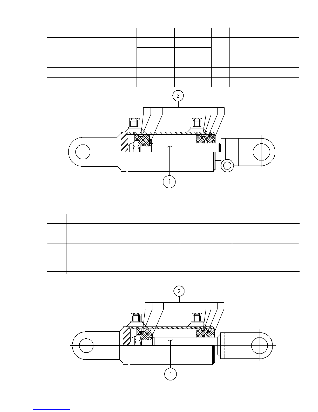
MODEL 672 & 674 AUGER CYLINDER
ITEM DESCRIPTION PART NO. PART NO. QTY. NOTES
672 674
2 1/2 x 14" 3 x 14"
Cylinder, Complete 9001091 94778 1
1 Rod 9001125 94881 1
2 Seal Kit 9001126 94879 1
250911
FLOW CONTROL DOOR CYLINDER
ITEM DESCRIPTION PART NO. QTY. NOTES
MODEL 674
S/N B18260100
Thru B18260164
2 x 36" 2 1/2 x 36"
Cylinder, Complete 9001092 93806 1
1 Piston Rod, 1 1/8" 9001128 93807 1
2 Packing Kit 9001130 91387 1
250912
• 06-23-00
2-19
Page 44
233214D
• 07-14-98
2-20
Page 45

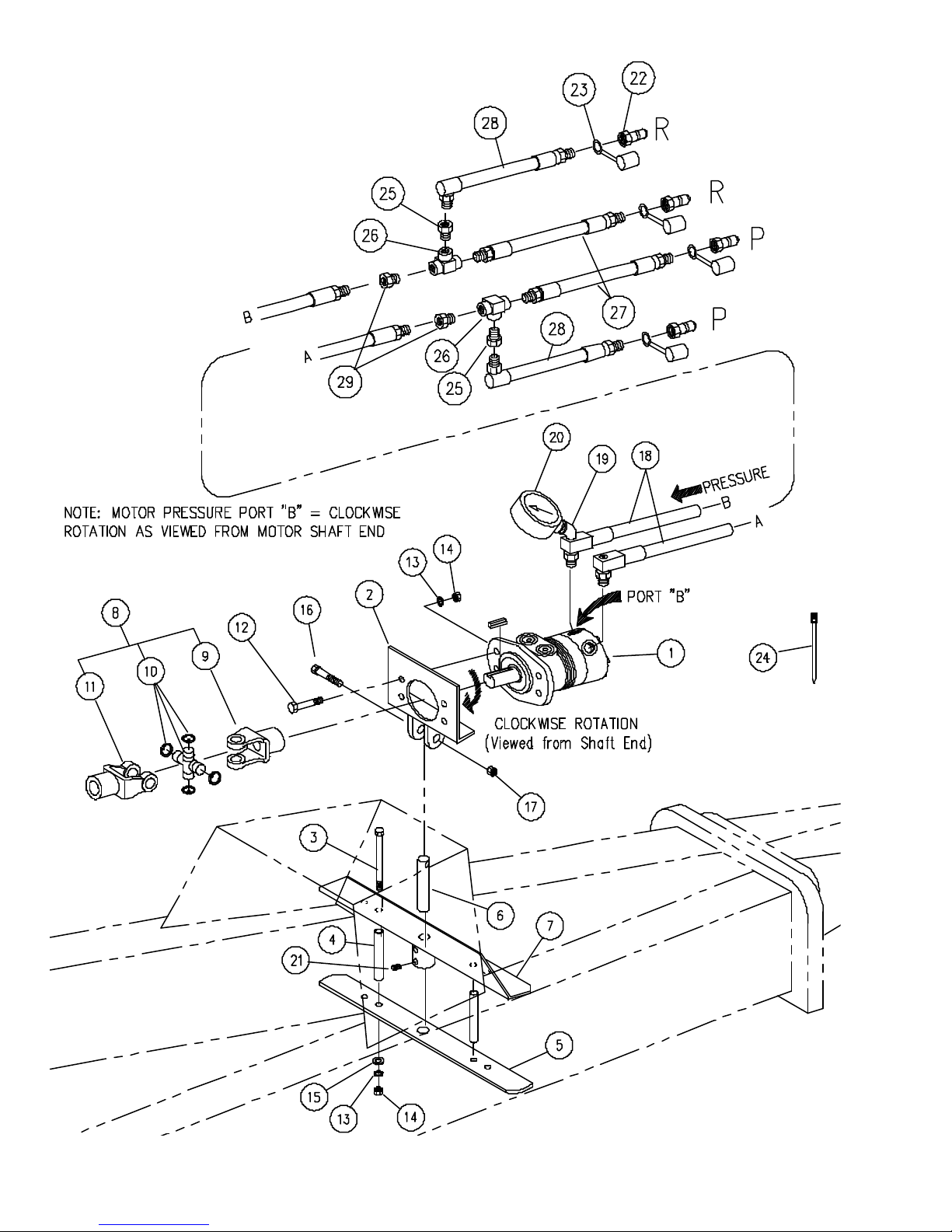
HYDRAULIC PTO DRIVE
ITEM DESCRIPTION PART NO. PART NO. QTY. NOTES
672 674
Hydraulic Drive Assembly 250086 250087 1 Includes 1 thru 24
•
1 Hydraulic Motor, 15.9 in.
2 Mounting Plate Weldment 230028 > 1
3 Capscrew, 1/2UNC x 10 Hex 9390-436 > 2
4 Pipe 200191 > 2
5 Base 200185 > 1
6 Shaft, Adjusting 200128 > 1
7 Header Weldment 200201 > 1
8 U-Joint Assembly 9001084 > 1 Includes Items *
U-Joint Assembly 9001043 > 1 Includes Items ^
9 Yoke, 1-1/4" Bore / 5/16" Key 9001168 > 1 *
Yoke, 1-1/4" Bore / 1/4" Key 92481 > 1 ^
Key, 5/16" 250268 > 1 *
Key, 1/4" 250265 > 1 ^
10 Cross Kit with Retaining Rings 92479 > 2 * ^
11 Yoke, 1-3/8"-21 Spline 92480 > 1 * ^
12 Capscrew, 1/2-13 UNC x 2 9390-103 > 4
13 Lockwasher, 1/2 9404-025 > 4
14 Nut, 1/2-13 UNC Hex 9394-010 > 6
15 Flatwasher, 1/2 9405-087 > 2
16 Capscrew, 1/2-13 UNC x 2-1/2 9390-105 > 1
17 Nut, Center Lock, 1/2-13 UNC 94981 > 1
18 Hose, 3/4 I.D. 9001038 > 2
19 Elbow, 45o Street 9001040 > 1
20 Gauge, 0-3000 psi 9001039 > 1
21 Setscrew, 1/2-13 UNC Socket Hd. 9399-106 > 2
22 Disconnect, Male 93474 > 2 7/8-14 ORB F
23 Dust Cap 91511 > 2
24 Tie Strap, 20" 9891 > 4
25 Reducer Bushing 9001882 > 2
26 Tee 9001883 > 2
27 Hose, 3/4 x 12 9001885 > 2
28 Hose, 1/2 x 15 9001886 > 2
29 Adapter, O-Ring 9001918 > 2
3
9000744t 9000744 1 tRepl. 9000750-9.99 in.
3
• 09-04-01
2-21
Page 46
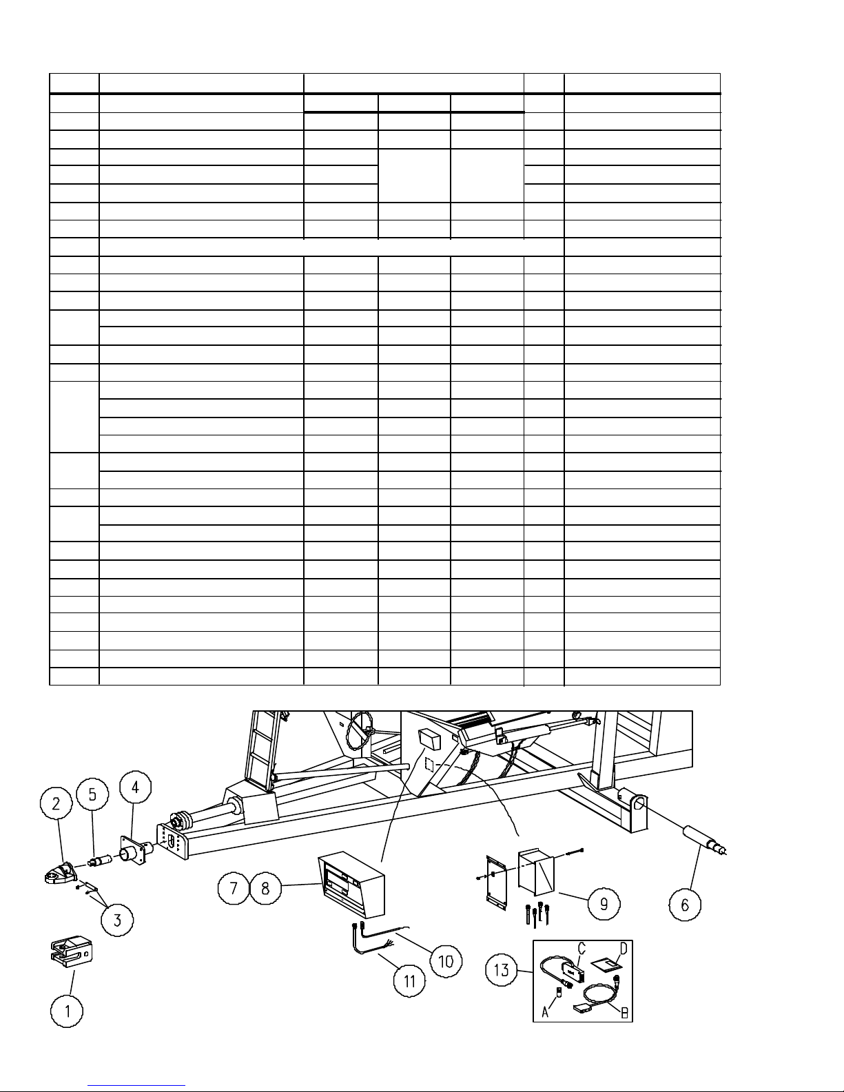
MODEL 672 & 674 - SCALE UNIT
ITEM DESCRIPTION PART NO. QTY. NOTES
Single Dual Dual
Hubs - B.C. 11 1/4" 13 3/16" 13 3/16"
Spindle Dia. 2 7/8" 3.730" 3.750"
674 S/N B1582100
Thru B165i099
672 S/N B1581100
Thru B1649099
•
•
EZ-2000 Scale Package 265337 265339 250389 Opt.Dealer Installed
EZ-3200 Scale Package 265345 265347 250390 Opt.Dealer Installed
Above Packages Include Spindle, Hitch & Indicator Items - Less Printer Specify Hitch Type
1 Scale Hitch, Clevis 200004B > > 1
2 Scale Hitch, Single-Tang 250494B > > 1
3 Pin 250844 > > 1 Repl. 250490 As
Snap Ring 91192 > > 2 Repl. 94142 Set
4 Bushing, Scale Hitch 250487B > > 1
5 Weigh Bar -- 2 1/2" Dia. 92400 > > 1
6 Spindle (1.75" Outer Brg Cone) 92442 2
Spindle (2.25" Outer Brg Cone) 9003020 2
Spindle Kit (3.75" Spindle,Bushing,Fstnrs) 265684 2
Spindle 9002009 2
7 Scale Indicator Box (EZ-2000) 9002660 9002661 > 1 Standard Scale Kit
•
•
Scale Indicator Box (EZ-3200) 9001338 9001220 > 1 Kit for Printer Option
8 Bracket, Indicator Box 200159B > > 1
9 Scale J Box w/ 30' cord 9002852 > > 1
J-Box Cord only 30' 9000473 > > 1
10 Scale Power Cord 92452 > > 1
11 Scale Cab Extension Cord 92453 > > 1
12 Roll Printer Only (Not Shown) 265263 > > 1 EZ210 & EZ150 w/print option
13 Memory Module Downloader Kit 9002723 > > 1 EZ210 & EZ150 w/print option
A Downloader Module 9002724 > > 1
B Interface Cable 9002833 > > 1
C Memory Converter 9002834 > > 1
D Software 9002835 > > 1
NOTE: All scale packages are shipped with single-tang hitch unless specified otherwise.
674 Beginning With
S/N B165i100
672 Beginning With
S/N B1649100
Repl. 92443 3.73", Incl.250684,250685
250948
250948
• 09-10-02
2-22
Page 47
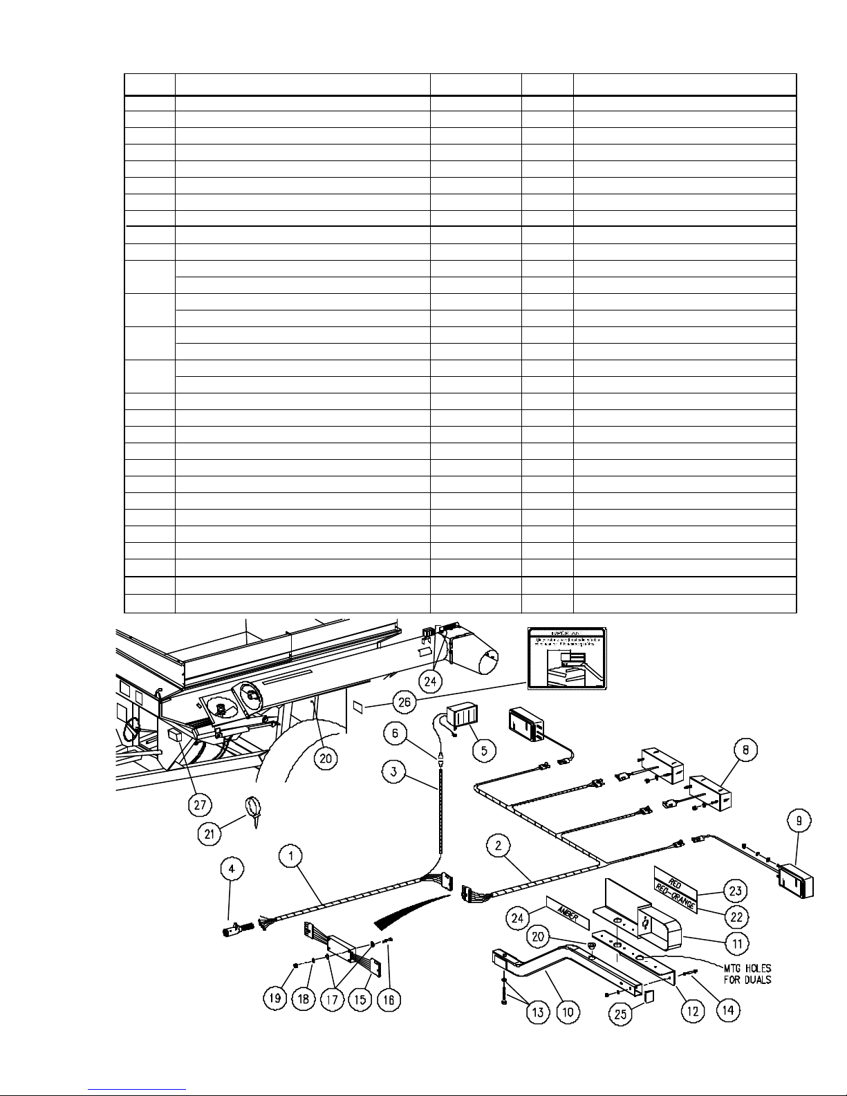
MODEL 674 - ELECTRICAL
BEGIN SERIAL #B19380100
ITEM DESCRIPTION PART NO. QTY. NOTES
1 Wiring Harness, Front 9003509 1
2 Wiring Harness, Rear 9003510 1
3 Wiring Harness - Auger 9000375 1
4 Electrical Coupler 92450 1
5 Auger Light 9001155 1
•
6 Connector, Male 9001660 2
•
7 Not Applicable
8 Light, Red - Tail/Turn 9003136 2
9 Light, Amber - Turn/Flasher 9003048 2
10 Light Tube Weldment 251398B 2
11 LH Light Bracket Weldment (Shown) 251409B 1
RH Light Bracket Weldment 251408B 1
12 LH Plate 251406B 1
RH Plate 251407B 1
13 Capscrew, 1/2-13 UNC x 3 1/4 9390-108 2
Locknut, 1/2-13 UNC 9003397 2
14 Capscrew, 1/4-20 UNC x 2 9390-009 4
Locknut, 1/4-20 UNC 9936 4
15 Light Module 9003045 1
16 Machine Screw, #6-32 x 1 1/4 9401-010 2
17 Flatwasher 9405-040 4
18 Lockwasher, #6 9404-009 2
19 Nut, #6-32 UNC 9830-013 2
20 Grommet 9001816 8
21 Cable Tie 9000106 11
22 Fluorescent Strip, Red-Orange 9003125 2 2 x 9"
23 Red Reflector 9003126 2 2 x 9"
24 Amber Reflector 9003127 4 2 x 9"
25 Tube Plug 9003515 2
26 Decal, Light Placement 9003518 1
27 Scale Unit Page 2-22 Option
250987
• 09-10-02
2-23
Page 48
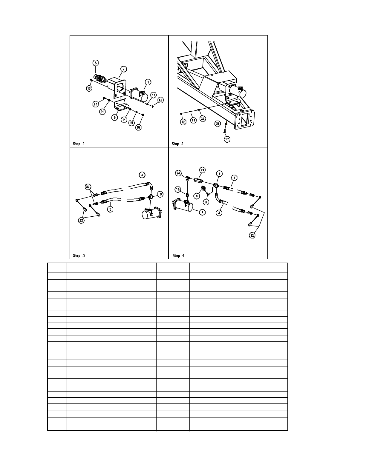
HYDRAULIC DRIVE KIT (OPTIONAL)
•
•
•
•
•
•
•
•
•
•
•
ITEM
1
2
3
4
5
6
7
8
9
10
11
12
13
14
15
16
17
18
19
20
21
22
23
24
DESCRIPTION
Hydraulic Drive Kit
Hydraulic Motor
Hose, 3/4" I.D. x 88"
Hose, 3/4" I.D. x 88" 90°
Run Boss Tee
Pressure Gauge
Elbow, 1/4 Male x 1/4 Female
Mount Weldment, Motor
U-joint Assembly
Plate, Bolt
HCS 1/2-13UNC x 1 3/4
Lock Washer, 1/2
Hex Nut, 1/2-13UNC
HCS, 5/8-11UNC x 1 1/2
Flat Washer, 5/8
Lock Washer, 5/8
Hex Nut, 5/8-11UNC
HCS, 1/2-13UNC x 2
Adapter
Run Boss Tee
Male Tip Coupler
Check Valve
Dust Cap
Flat Washer, 1/2
Swivel Nut Elbow, 90°
PART NO.
280102
9004283
9004295
9004296
9004285
9001039
9004304
280066B
9004284
280069B
9390-102
9404-025
9394-010
9390-122
9405-098
9404-029
9394-014
9390-103
97618
9004399
93474
9004385
91511
9405-086
99631
QTY.
1
1
2
2
1
1
1
1
1
1
4
6
6
2
4
2
2
2
1
1
4
1
4
4
1
280911
NOTES
1 5/16-12 JICM x 1 5/16-12 M-O-R
•
•Revised 122904-2
2-24
Page 49

SECTION III - SCALE
SCALE KIT LAYOUT & INSTALLATION................................................... 3-2
SCALE MODEL 150
OPERATION .......................................................................................... 3-4
INSTALLATION REQUIREMENTS ......................................................... 3-6
SHORT-FORM SET-UP/CALIBRATION ................................................... 3-7
CHANGE LBS TO KGS ......................................................................... 3-9
CHANGE UPPER RANGE .................................................................... 3-10
DOWNLOADER MODULE ..................................................................... 3-11
TROUBLESHOOTING GUIDE ............................................................... 3-12
IMPORTANT
READ THIS BEFORE USING YOUR SCALE
THE FOLLOWING STEPS MUST BE CONSIDERED WHEN USING
YOUR SCALE AND TO REALIZE ITS BEST PERFORMANCE.
DIGI-STAR SCALES ARE MANUFACTURED TO PROVIDE 1/2%
MAXIMUM ERROR. A GOOD INSTALLATION AND PROPER USE ARE
REQUIRED IN ORDER TO OBTAIN ADVERTISED ACCURACY.
+
A GOOD INSTALLATION REQUIRES THAT ALL LOAD CELLS ARE
PROPERLY INSTALLED WITH "TOP" ACCURATELY POSITIONED.
OPERATION
TO INSURE 1/2% MAXIMUM ERROR, THE UNIT MUST BE USED AS
+
A STATIONARY LOAD-OUT WEIGH HOPPER FROM BIN TO TRUCK,
FOR EXAMPLE, THE GROUND MUST BE SMOOTH AND LEVEL WITH
MAXIMUM 5" SLOPE PER 10 FEET.
TO INSURE 1% MAXIMUM ERROR, THE UNIT MUST BE USED SO
+
THAT ALL WEIGHT MEASUREMENTS OCCUR ON FLAT, SMOOTH
GROUND (MAXIMUM OUT OF LEVEL 10" IN 10 FEET) IDEALLY, ALL
WEIGHT MEASUREMENTS FOR A FIELD WOULD OCCUR IN THE
SAME SPOT.
WARNING!
ALWAYS DISCONNECT CABLES FROM SCALE
INDICATOR BEFORE JUMP STARTING ENGINE
• 04-01-02
3-1
Page 50
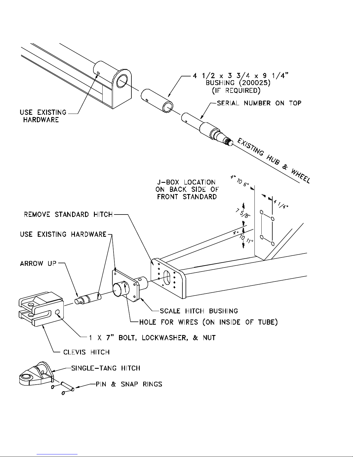
SCALE KIT LAYOUT
250917
• 04-16-01
3-2
Page 51

INSTALLATION OF SCALE KIT
FOR MODELS 672 & 674
HITCH ASSEMBLY
1. Remove the four 3/4 x 2 1/2" bolts
(9390-146) and lockwashers (9404-
033) to remove the standard hitch
(250486).
2. Using the same bolts and
lockwashers, install the scale hitch
bushing (250487).
3. Before installing the 2 1/2" weigh
bar (92400), feed the wire through
the hole indicated in the drawing
at left. After doing so, insert the
2 1/2" weigh bar.
4. Using the 1 x 6" bolt (9390-195),
lockwasher (9404-041), and nut
(9394-020), secure the 2 1/2"
weigh bar.
SPINDLE ASSEMBLY
1. With the cart empty, use a 5-ton jack
and jack stands to support the weight
of your grain cart. Place the jackstands under the axle, near the tire.
2. Remove the wheel & tire and the hub
assembly. See part numbers below.
3. Remove the 5/8 x 6 bolt (9390-136),
lockwasher (9404-029), and locknut
(9395-014) to release the spindle.
4. Change the seal in the hub.
5. Using the same bolt, lockwasher, and
locknut you just removed, add the
4 1/2" spindle bushing (200025) if
required and the spindle.
6. Attach hub assembly and the original
wheels & tires.
5. Using a 1 x 7" bolt (9390-197),
lockwasher (9404-041), and nut
(9395-020) secure the clevis hitch
(200004). Use the pin (250490)
and two snap rings (94142) to
secure the single-tang hitch
(250494).
J-BOX INSTALLATION
1. Install junction box on the back
side of the left front frame standard (see drawing at left).
2. See page 3-6 for specific wiring
installation instructions.
• 04-16-01
NOTE: Tighten lug nuts to 400 ft. lbs.
S/N 674 #B1651099 / 672 #B1649099 & Lower
2 7/8" 4 1/2" 3 3/4"
Singles Duals Duals
Standard Scale
Hub, St'd & Scale 200036
Hub, Duals 200144 200145
Spindle, Standard 200176 200177
Spindle, Scale 92442 92443
Bushing 200025
S/N 674 #B1651100 / 672 #B1649100 & Higher
3 3/4" 3 3/4"
Singles Duals
Hub, Standard & Scales 200079 200145
Spindle, Standard & Scales 250601 9002009
INDICATOR INSTALLATION
1. Using the bracket provided, locate
the indicator inside the tractor cab.
2. Attach the cable as indicated on
page 3-6.
3-3
Page 52
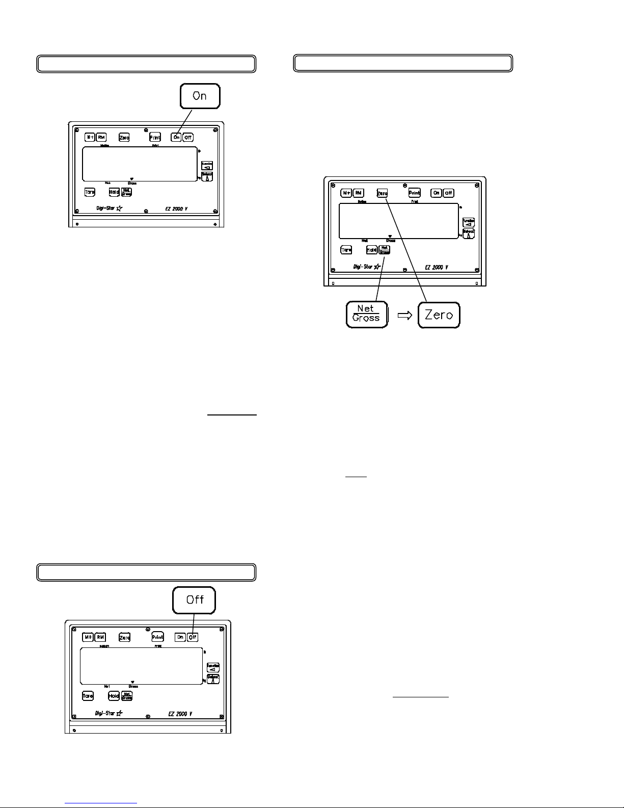
Turn ON the scale:
To Zero / Balance the Scale
1. Press [ON].
HELLO
250955
A brief message is displayed (such as
"HELLO" ). The scale enters GROSS
weighing mode. Pressing [ON] a sec-
ond time during normal system operation starts the self-test.
A warm-up period of ten to fifteen
minutes provides the most accurate
readings. If the scale is holding a load
for a long period of time (ex: overnight), the weight displayed may vary
because of zero shift created by
changes in temperature. This does not
affect the accuracy of the scale.
For example, if the system was loaded
with 1000 Lbs, it might read 1200 Lbs
the following day. The change in
temperature "zero shifted" the ZERO/
BALANCE from 0 Lbs to 200 Lbs.
When unloading the scale, the display
will count from 1200 to 200 Lbs for a
total of 1000 Lbs.
Turning OFF the Scale:
1. Press [OFF].
0
1. Press the [NET/GROSS] key and
within three seconds,
2. Press the [ZERO] key.
ZERO
The ZERO/BALANCE will "balance off"
trailer, bin, or platform weight.
The "ZERO" message is displayed and
the scale is placed in the GROSS mode.
Pressing only the [ZERO] key will cause
the message "TO ZERO / BALANCE
PRESS NET/GROSS -- THEN ZERO"
to be displayed.
If the supply power is below the "low
battery threshold" (10.5 Volts), the
message "INDICATOR CANNOT BE
ZERO / BALANCED -- LOW BATTERY
VOLTAGE" is displayed. The
message "LO BAT" will be periodically
shown on the display (approx. every
five seconds) to alert the operator of
the low battery condition.
Loss of power does not affect the
ZERO/BALANCE or "Setup/Calibration"
values.
• 04-01-02
3-4
Page 53
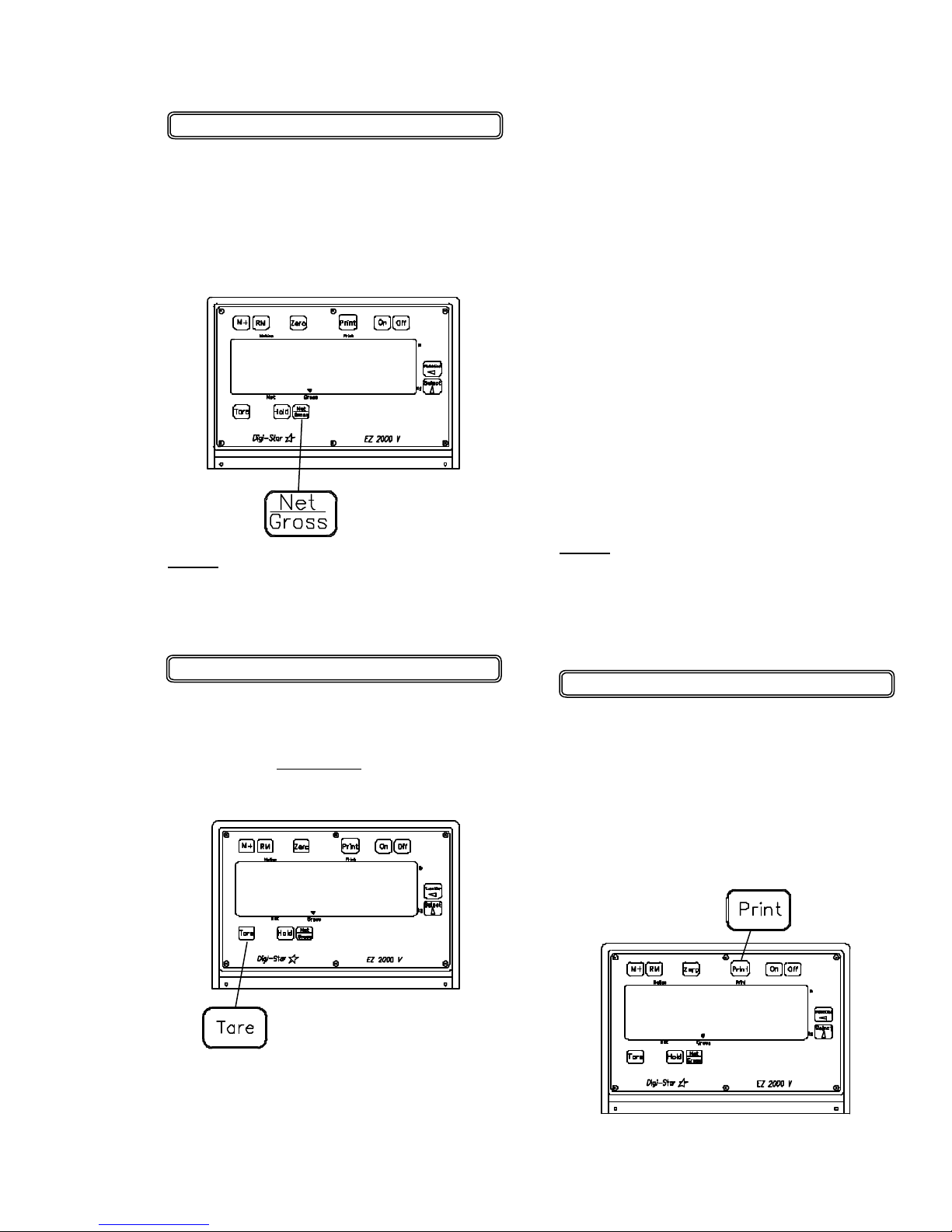
To Select Gross Mode:
or
GROSS mode displays the weight
change since the unit was last ZERO/
BALANCED.
1. Press [NET / GROSS].
9850
NOTE: The scale is in GROSS mode
if there is a flashing arrow pointing
toward the GROSS text just above the
[NET / GROSS] key.
2. If in Gross mode, press
[NET / GROSS].
The [NET / GROSS] key is an alternat-
ing action key. If the scale is in the
GROSS mode, pressing the [NET /
GROSS] key will place it in the NET
mode. If the scale is in the NET mode,
pressing the [NET / GROSS] key will
place it in the GROSS mode.
If the "TARE" function has not been
previously performed, the unit will stay
in the Gross mode and the message
"FOR NET MODE PRESS TARE" will
scroll across the display.
NOTE: The scale is in NET mode if
there is a flashing arrow pointing
toward the NET text just above the
[TARE] key.
To Select Net Mode:
Net mode displays the weight change
after a TARE has been performed.
TARE is a temporary "zero" or reference point.
0
1. Press "TARE" to set a temporary
"zero" point and enter the NET mode.
• 04-01-02
To Print
Scale data can be sent to the optional
printer by pressing the [PRINT] key.
The printer connector on the bottom of
the indicator is also used to connect
the optional downloader module
memory converter. See page 3-9.
3150
3-5
Page 54
•
OPERATION:
It is recommended that the indicator reads
0000 by pressing TARE before unloading the cart in a truck or wagon.
Once the cart is finished unloading, the
exact (negative) amount of grain unloaded
is displayed.
Press TARE to read 0000 again, or press
NET/GROSS to display the amount of
grain remaining in the grain cart.
INSTALLATION
Indicator Mounting:
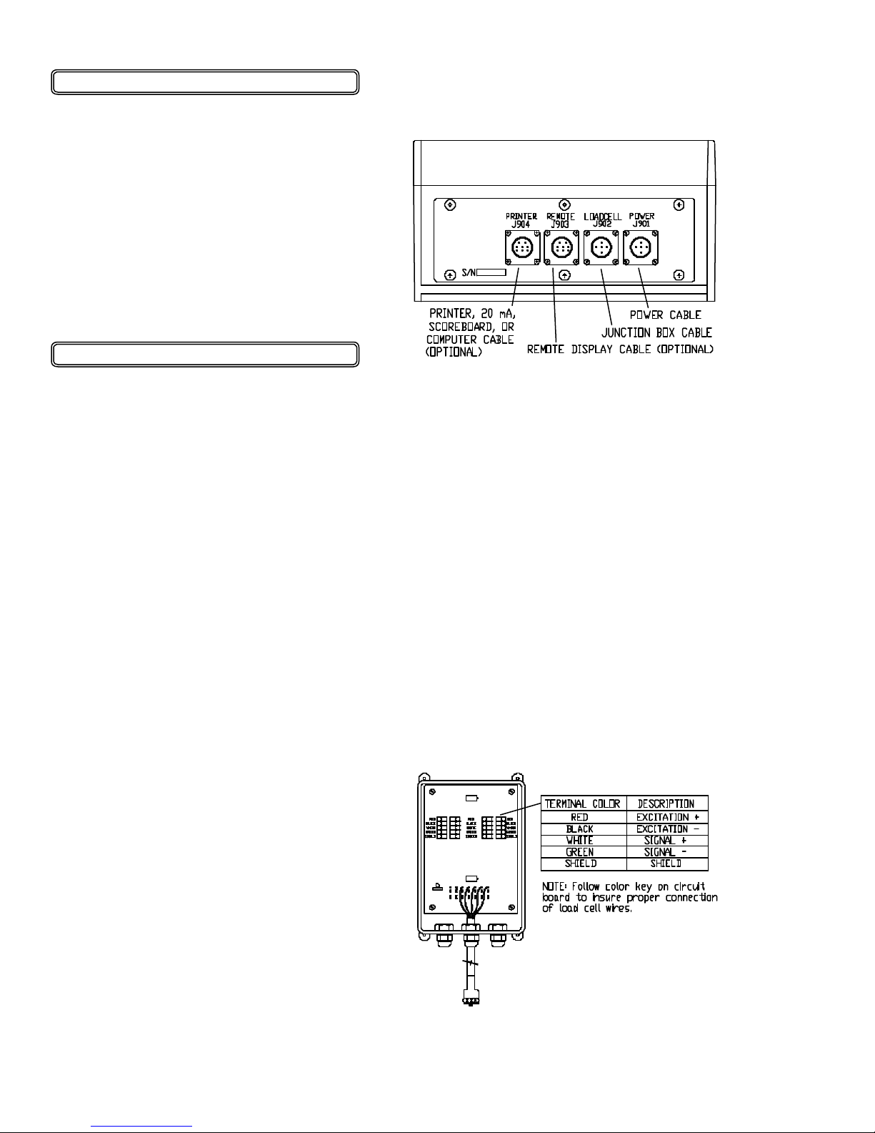
The indicator is easily attached to the Indicator Mounting Bracket by hooking the top
over the plate and securing the bottom with
two (2) bolts (size# 10 x 24 x 3/4") and nuts.
Power Connection:
The power cable should be connected directly to a vehicle battery or regulated power
supply. The scale end of the power cable is
attached to the J901 connector located on
the bottom panel of the scale.
Connect the RED wire from the power cable
to +12 VDC and the BLACK wire to
GROUND. The indicator is fused internally
at 4 amps.
SCALE BOTTOM PANEL
CABLE CONNECTIONS:
Load Cell Connection:
The indicator is designed to operate with
strain gage load cells. The indicator will
normally be supplied with a "J-BOX" cable
going between the scale and the load
cell junction box. Extension Kits are
available from your dealer in various
lengths.
To connect the load cells, attach the
junction box cable to the J902 connector
on the bottom panel of the scale. Connect the load cell cables to the junction
box as shown below.
POWER CABLE CONNECTIONS:
WIRE COLOR WIRE FUNCTIONS
RED Battery (+12 VDC)
BLACK GROUND
ORANGE Remote Alarm Out +
BLUE Remote Input
Remote Alarm Connection:
If a remote 12 VDC alarm is to be used,
connect the +12 VDC side of the alarm to
the power cable orange wire and the
GROUND side (or black wire) to the frame.
The alarm output is fused for a maximum
drain of 10 amps. The remote alarm connection may also be used for motor control
purposes when used with a relay.
JUNCTION BOX LOAD CELL
CABLE CONNECTIONS:
• 12-19-01
3-6
Page 55
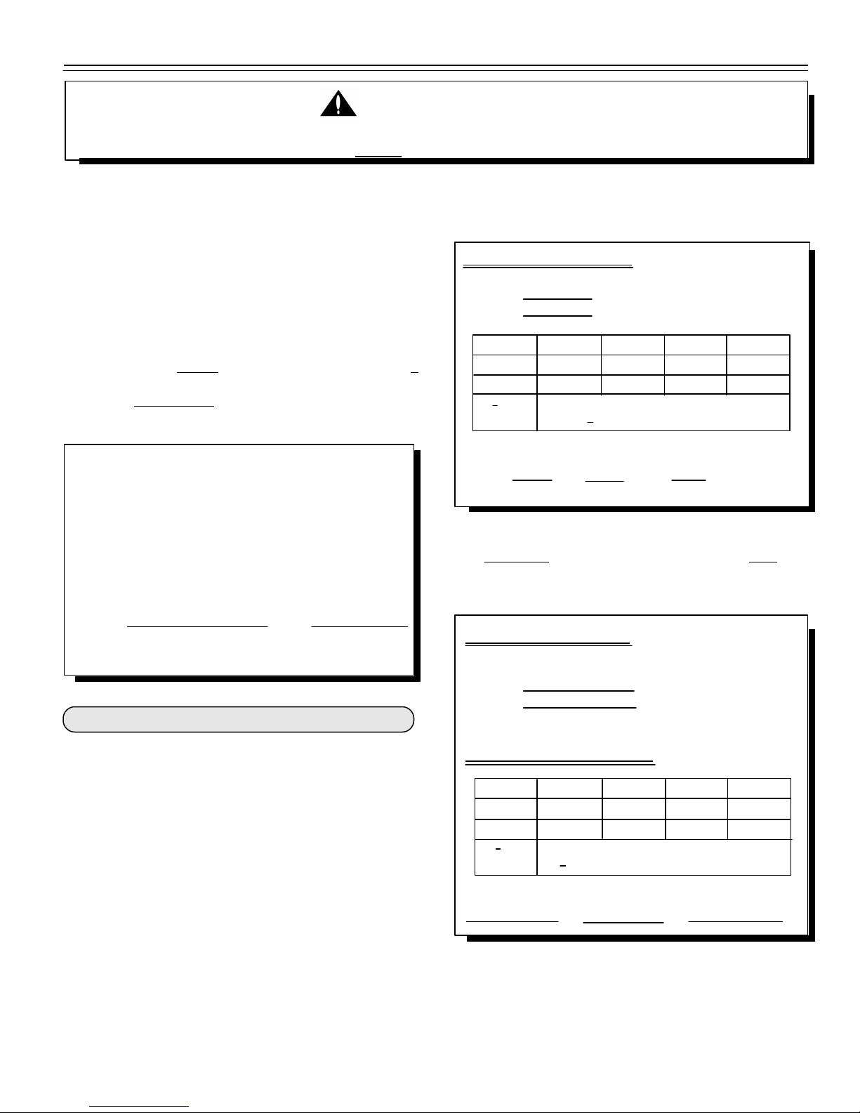
"Short Form" Setup & Calibration:
WARNING!
THIS INDICATOR WAS CALIBRATED AT THE FACTORY TO WEIGH ACCURATELY WITH YOUR SYSTEM.
ADDITIONAL CALIBRATION IS NOT NECESSARY UNDER NORMAL CONDITIONS.
The Short Form Setup & Calibration procedure allows
you to change the "SETUP" and "CAL" numbers of the
indicator. You may want to perform this procedure if;
1): The indicator is being connected to different load
cells.
or
2): You want to adjust the calibration to match
another scale system.
PLEASE NOTE: Do not attempt to calibrate the scale if
the indicator is not reading stable weights. The calibration
procedure will not fix instability, inconsistencies, or
flashing "RANGE" messages.
Before continuing, first write down the current
"SETUP" and "CAL" numbers of your EZ indicator.
These numbers are displayed during the "Self Test".
To run the Self Test:
With the indicator already ON, press the [ON] key to
start the Self Test. Press the [ON] key to "pause" the
Self Test while numbers are displayed. Press [ON]
again to "resume".
It is important to use an average of several weights before
calibrating the scale.
Scale Matching Example:
Original
SETUP# 127070
CAL # 23980
1 trial 2 trial 3 trial
Scale B 30,000 30,580 28,000
Scale A 29,440 29,800 27,500
B : A 1.020 + 1.026 + 1.018 = 3.064
3.064 : 3 trials = 1.021 Cal. Multiplier
New EZ CAL# = Orig. EZ CAL# x Cal Multiplier
24484 = 23980 x 1.021
You should not modify your "SETUP" number. Only your
"CAL" number.
SETUP# CAL#
Keep this information for future reference.
1: Adjust EZ Indicator to Match Another Scale:
Sometimes two different scales are used to weigh the
same load. When this is done, the weight
measured by each scale may not be the same. This can
be caused by one or both of the two scales being slightly
out of calibration. This indicator has the ability to match
any other scale, even if that scale is uncalibrated.
To match your EZ scale (Scale A) to another scale
(Scale B) you must determine the Calibration
Multiplier. To do this, place a load on Scale A
(feed wagon, etc...) and write down the weight displayed.
Repeat several times to determine the average weight.
Next, place the same load on Scale B and again write down
the weight displayed. Again, repeat several times to
determine the average weight. Then, use this formula to
determine the Calibration Multiplier for the EZ's
"CAL" number:
• 06-30-00
Scale Information Sheet:
Original
SETUP#
CAL#
Scale Matching Work Sheet:
1 trial 2 trial 3 trial
Scale B
Scale A
B : A + + = "x"
"x" : 3 trials = Cal. Multiplier
New EZ CAL# = Orig. EZ CAL# x Cal Multiplier
= x
Follow the instructions "To change the Setup /
Calibration Numbers" shown on the next page.
3-7
Page 56
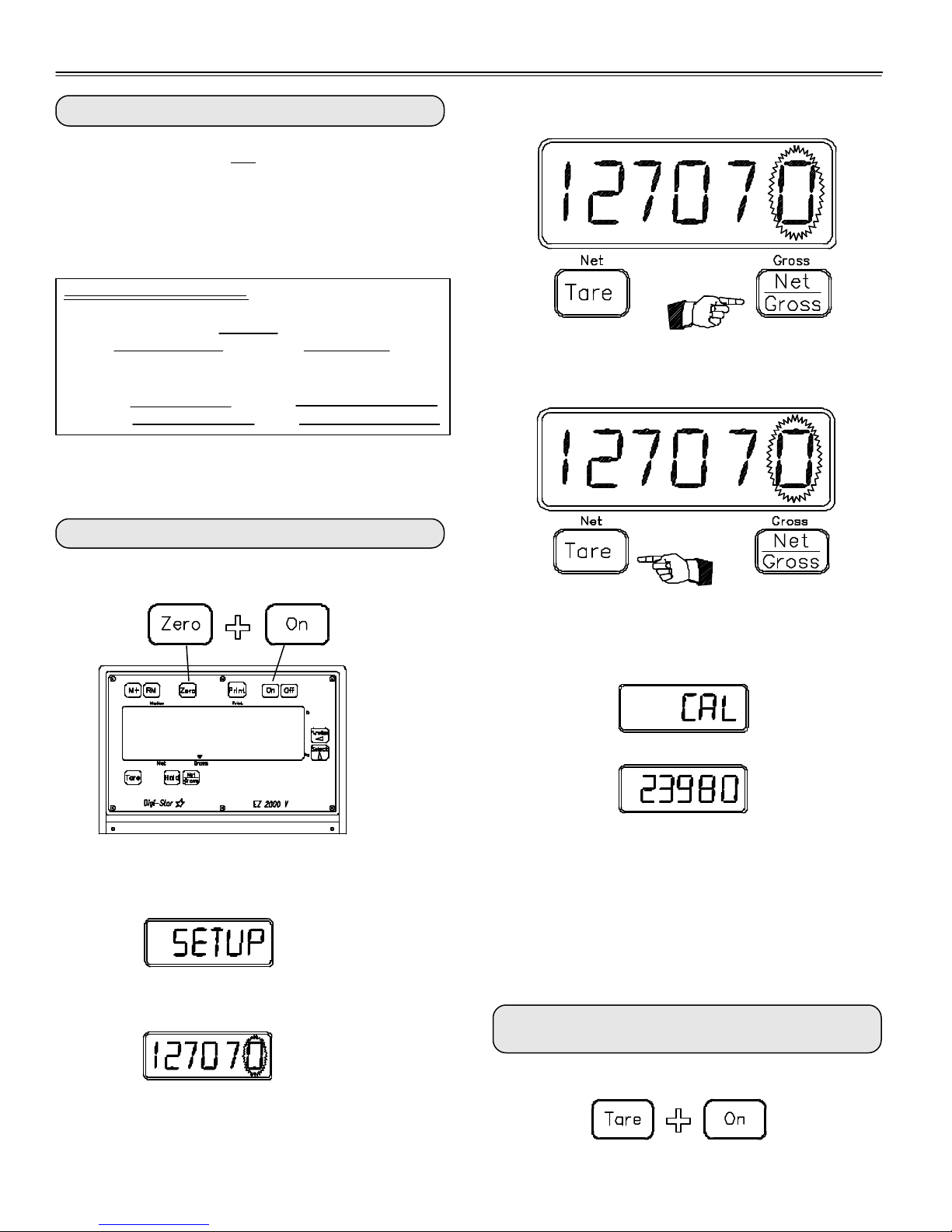
NOTE: Press the [ZERO] key for additional help information during Setup and Calibration.
1: Connecting EZ Indicator to Other Load Cells:
You will need the number and type of loadcells used in the
new scale system. You will also need the
current "SETUP" and "CAL" as described above. Once
you have written down this information, contact your
nearest Scale Service Center for new "SETUP" and
"CAL" numbers.
Scale Information Sheet:
Load Cells: Number=
Type = Output =
mV/V
Original New
SETUP# SETUP#
CAL# CAL#
Follow the instructions "To Change the Setup / Calibra-
tion Numbers" shown below.
To Change the Setup/Calibration Numbers:
Step 1) Press the [NET/GROSS] key to cause the
"flashing" digit to count upward.
Step 2 Press the [TARE] key to select which digit is
flashing.
Press and hold the [ZERO] key, then press the [ON] key,
to enter Short Form Setup & Calibration.
3150
250955
The first message displayed is "SETUP"
Next, the actual "SETUP" number is displayed.
When the correct "SETUP" number is displayed, press
the [ON] key to advance to the "CAL" number.
This displays the "CAL" message,
followed by the "CAL" number.
The "CAL" number is not a weight. It is a reference value
the indicator uses to determine the weight. This number
directly affects the accuracy of the scale system.
Change the "CAL" number using the same method
described in Steps 1 & 2. When the display shows the
correct number, press the [ON] key. This causes the
number to be stored permanently in the indicator and
returns the indicator to the weighing mode.
To Exit the Short Form Setup & Calibration at
Anytime:
If the correct "SETUP" number is displayed, press [ON]
to advance to the "CAL" number.
Press and hold the [TARE] key, then press the [ON] key.
• 04-01-02
3-8
Page 57
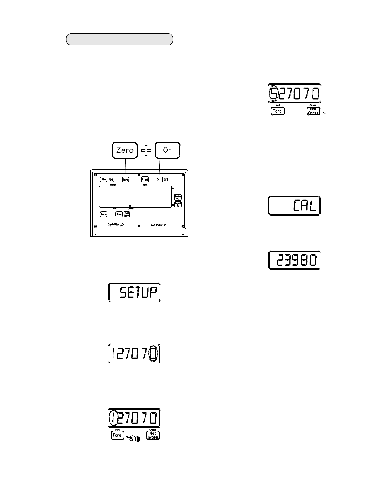
To change scale from lbs to kgs:
1. Press [ON] to turn on the scale.
2. To enter Short Form Calibration &
Setup press and hold the [ZERO]
key, then press the [ON] key and
hold them both together until the
indicator displays "setup", then let
up on the keys.
9850
4. Press the [NET/GROSS ] key to
increment the "flashing" digit.
Change the 1 to 5.
5. Press the [ON ] key to
advance to the "cal" number.
The "cal" message is displayed.
250955
The first message displayed is "SETUP"
Next, the actual "SETUP" number is displayed with the far right digit "flashing".
3. Press the [TARE] key to select the
far left digit as the "flashing digit".
Then the "cal" number.
When the 1 was changed to a 5 in
the setup number, the "cal"
number was automatically recalibrated to kgs.
6. Press [ON] to exit setup.
• 04-01-02
3-9
Page 58
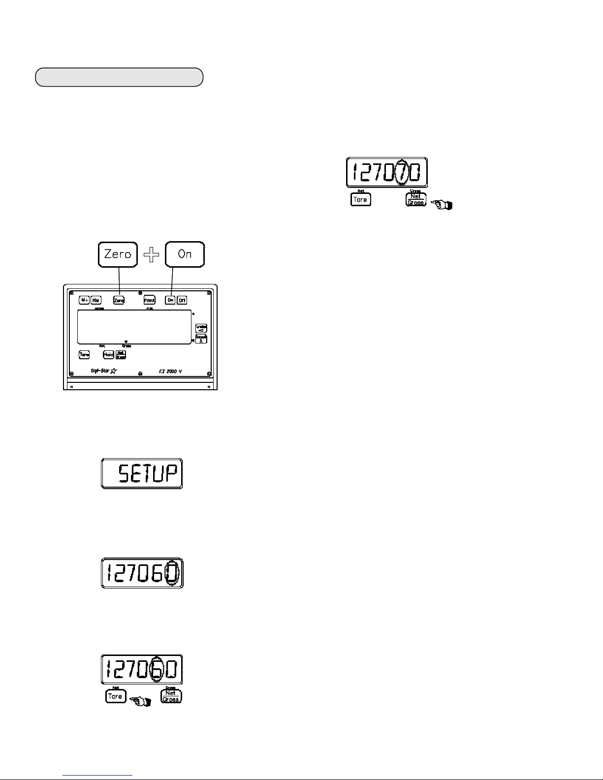
To change scale upper range:
1. Press [ON] to turn on the scale.
2. To enter Setup press and hold the
[ZERO] key, then press the [ON]
key and hold them both together
until the indicator displays "setup",
then let up on the keys.
9850
4. Press the [NET/GROSS ] key to
increment the "flashing" digit.
Change the 6 to 7 (700000#) or
desired higher number.
5. Press [ON] to exit setup.
250955
The first message displayed is "SETUP"
Next, the actual "SETUP" number is displayed with the far right digit "flashing".
3. Press the [TARE] key to select the
"6" (600000#) as the "flashing digit".
• 04-01-02
3-10
Page 59
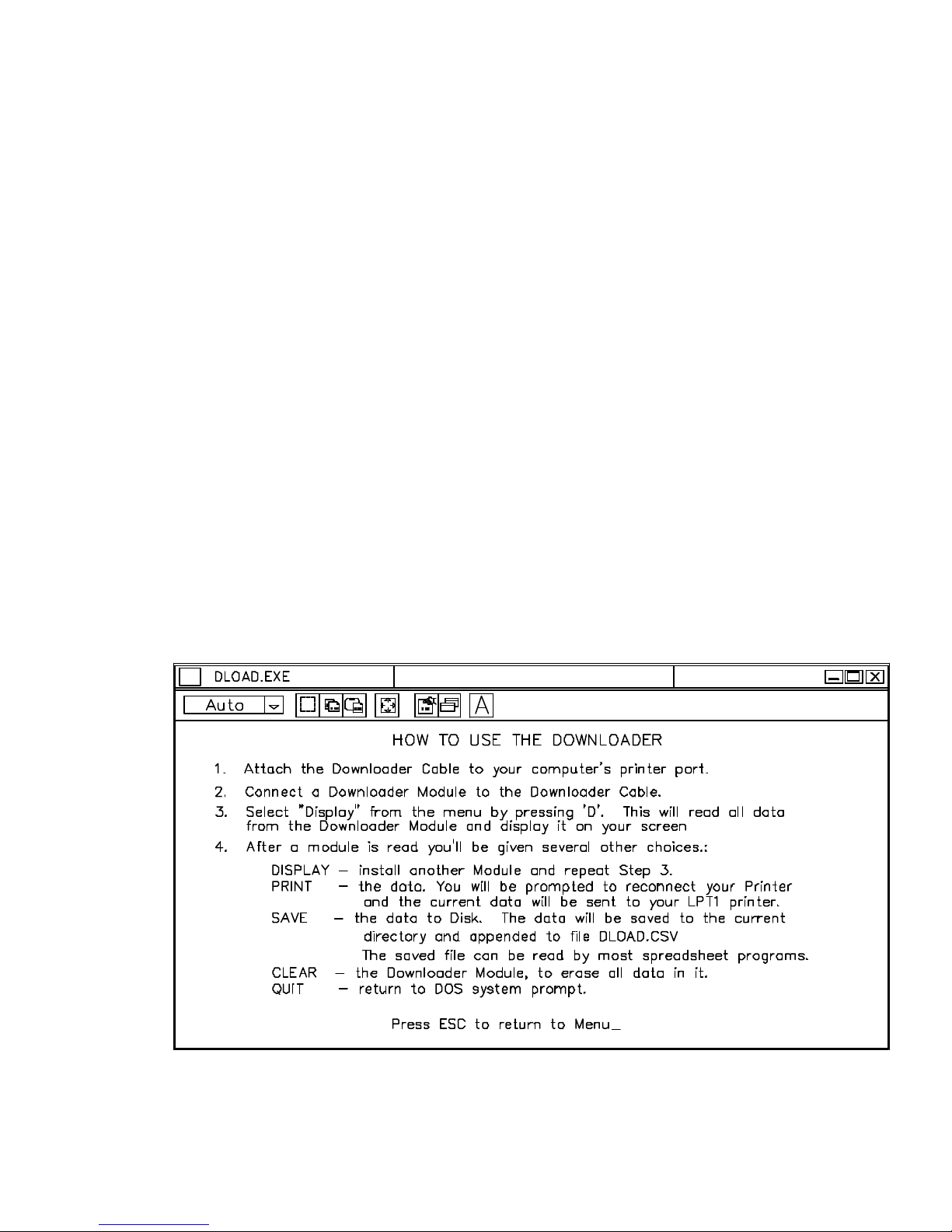
DOWNLOADER MODULE (Optional)
Quick Guide
Suggestion: You may want to manually keep a log of dates and times at
various farms and fields to check and identify the scale indicator data.
1. Plug the Memory Converter into the bottom of the scale indicator and the
downloader Module into the Memory Converter.
2. Operate the scale normally, making sure to press PRINT whenever you want the
Downloader to store data.
3. Remove only the Downloader Module when you are finished weighing.
4. Plug the Interface Cable into your computer's parallel (printer) port and attach
the Downloader Module to the Interface Cable.
5. Start the Downloader program by typing DLOAD. (Use DLOADER if you want to
save only new data to your file.)
6. Follow the onscreen instructions to Display, Save, or Print your data.
7. Clear the Downloader Module when you have finished so that more data can be
stored into it.
250955
Refer to the Manufacturer's Operation and Installation Manual for complete instructions, trouble-shooting, and scale set-up/configuration guide.
• 06-23-00
3-11
Page 60
Digi-Star Scale - Troubleshooting Guide
Check for 12VDC at the junction between the
AC/DC converter power cord. If you do not
have a multimeter, use a car battery to power
the scale. If the indicator still does not come on,
send it in for repair.
Does the scale weigh you close to
your weight? (Within 20%)
Yes
The scale system is probably
OK. Check for debris around and
under the platform and load
cells. Check for warped or
damaged mounts on platform.
Check for debris under or around the scale
mounts or platform. Check the load cell cables
for cuts or flattened areas.
Disconnect one load cell cable from the indicator.
Press the indicator “TARE” button. (The indicator
display should go to zero.) Stand on the load cell.
Does the indicator display a reading about twice
your weight?
Yes
Disconnect the first load cell, connect the
other load cell to the indicator (use the
same connector). Stand over this load cell.
Does the indicator display a reading
approximately twice your weight?
No
Does the indicator turn on?
No
Yes No
The other load cell is defective. Check its cable
for cuts or flattened areas or send it back for repair.
Check the defective load cell by connecting it to the
indicator and verify that it does not weigh.
No
The other load cell is defective. Check its cable
for cuts or flattened areas or send it back for repair.
Yes
Does the indicator respond
when you step on the scale?
Disconnect one of the load cells and stand over
the connected load cell. Does the indicator
display a reading about twice your weight?
Yes
Disconnect the first load cell and connect the
other load cell to the same connector on the
indicator. Does the indicator display a reading
about twice your weight.
Yes
No
This load cell is OK. Disconnect the first load
cell and connect the other load cell to the same
connector. Now stand over the second load cell.
Does it weigh twice your weight
Yes
This load cell is defective. Check its cable for cuts
or flattened areas or send it back for repair. Double
check indicator using a known good load cell.
Try connecting the load cell to the other connector
on the indicator. Stand on the load cell; Does it
display approximately twice your weight?
Yes
Check the platform, and load cells for debris
and mud interference. Check mounts for
binding and obstructions.
The indicator is defective. Verify this by
substituting with a good working indicator.
No
Connect both load cells (one at a time)
to the other connector on the indicator.
Do both load cells weigh you about
twice your weight?
No
No
Yes
Yes
No
Do both load cells weigh you the same
but not within 20% of twice your weight?
Yes
Perform the paper clip test. Take two paper clips
and carefully insert one in pin 2 and the other in pin
3 of either load cell connector jack on the indicator.
Hold one paper clip in each hand. (If they touch, it
While inserting the paper clips, does the reading on
the indicator jump around and/or settle on the
number “1” on the left side of the display?
Both load cells are defective and the indicator
is probably OK. Check the cables for damage or
send both load cells in for repair.
The indicator is defective. Send it in for repair.
Note: Load cells may also be defective. Check load
cells by attaching to a good working indicator.
One of the load cells is bad. A good load
cell will weigh you at approximately twice
your weight with only one cell connected.
will not damage the indicator.)
Yes
No
• 06-30-99
3-12
Page 61

WHY YOU SHOULD EQUIP YOUR
BRENT GRAIN CART WITH SCALES!
Ø Have convenience and time savings of 99% accurate "on-site" weighing, while
eliminating costly trips to stationary scales.
Ø Record yield and comparison information of seed varieties, fertilizer rates, soil
types, etc. to better manage inputs. See the comparison as you haul the crop
out of the field.
Ø More easily manage "sharecropping" arrangements between landlord and
tenant, particularly when grain needs to be delivered to multiple sites.
Ø Know exactly what you have placed in storage on the farm.
Ø Record exactly what you take out of storage and haul to the elevator.
Scales can be easily installed to your Brent grain cart at any time without any
modification. The scale investment increases the grain cart's trade-in value, so
the investment in the scale option is quickly returned.
See your Brent dealer for more information on converting your grain
®
cart to a Weigh Cart
today.
• 06-30-99
3-13
Page 62

NOTES
3-14
Page 63

SECTION IV - TARP
Tarp Parts ........................................................ 4-2
674 S/N B1651100 Thru B18260999
672 S/N B1649100 Thru B17480999
Tarp Installation.............................................. 4-4
674 S/N B1651100 Thru B18260999
672 S/N B1649100 Thru B17480999
Tarp Parts
674 Beginning S/N B18590100 ............. 4-8
Tarp Installation
674 Beginning S/N B18590100 ...........4-10
• 01-22-01
4-1
Page 64
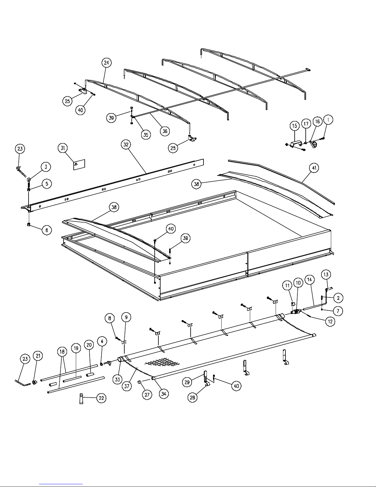
250932
• 11-13-97
4-2
Page 65

MODELS 672 & 674 - TARP
ITEM DESCRIPTION PART NO. QTY. NOTES
Tarp Kit w/End Caps 250320 1 Includes Items 1 Thru 41
Tarp Package 9001505 1 Includes Items 1 thru 37
1 Capscrew, 1/2-13 x 1 Flange 9001529 1
2 Capscrew, 3/8-16 x 1 3/4 9001530 1
3 Eyebolt 9001531 1
4 Flatwasher, 3/8 9001532 1
5 Nut, 5/16-18 9001533 1
6 Locknut, 5/16-18 9001534 1
7 Nut, 3/8-16 Centerlock 9001535 1
8 Screw, 1/4-14 x 3/4 Self Tapping 9001536 6
9 U-Clamp 9001537 6
10 U-Joint, Splined 9001538 1
11 Pin, Wire Lock 9001539 1
12 Spring Pin, 3/8 x 2 9001540 1
13 Crank Arm w/Handle 9001541 1
14 Extension, Crank Arm - 96" Lg. 9001582 1
15 Standoff, Crank Retainer 9001543 1
16 Retainer, Crank - Pinless 9001544 1
17 Retainer Bushing 9001545 1
18 Tube, Roll Return 9001546 2
19 Tube, Roll Returns 9001570 1
20 Connector, Tube 9001548 1
21 End Plug, Tube 9001549 1
22 Adhesive, Plastic - 2 Gram Tube 9001550 1
23 Stretch Cord, 198" Lg. 9001571 Cut Length per Instructions
24 Bow 9001565 4
25 Bracket, Bow - Long 9001933 8
26 Self-Tapping Screw, #8-32 x 3/8 9002105 1
27 Insert, Round - 1 1/8" Tube 9001555 2
28 Stop, Tarp 9001556 3
29 Cap, Tarp Stop 9001557 3
30 Installation Instructions 9001558 1
31 Decal, Caution / Operation 9001559 1
•
32 Latch Plate, Front 9002088 1 81 1/2" Lg.
Latch Plate, Rear 9002089 1 81 1/2" Lg.
•
33 Roll Tube w/Spline - Swaged 9001755 1 2" OD x 85"
Roll Tube w/Spline 9001765 1 2" OD x 85"
34 Fixed Tube - Swaged 9002085 1 1 1/8" x 81 1/2"
•
Fixed Tube 9002084 1 1 1/8" x 81 1/2"
35 Bracket, Ridge Pole 9001563 2
36 Ridge Pole 9001575 1 1 1/8" OD x 140 1/2"
37 Fabric Tarp 9001671 1
38 End Cap 250438 2
39 Capscrew, 1/4-20 x 1 9390-005 8
Locknut, 1/4-20 Centerlock 9936 8
40 Flange Screw, 3/8-16 x 3/4 95585 40
Flange Nut, 3/8-16 91263 40
41 Trimlock 9000787-180 1 15'
• 06-30-00
4-3
Page 66
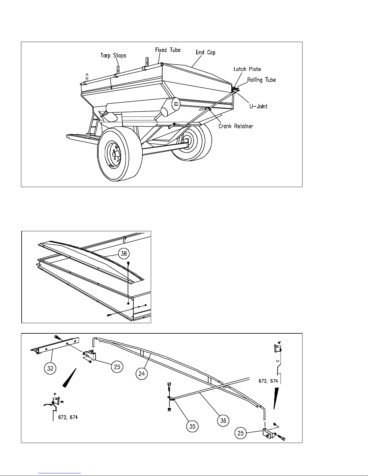
TARP INSTALLATION
Fig. 1
1. Install side board extensions to box.
See page 1-6.
2. Assemble end caps (38) to front and
rear side boards. See Fig. 2.
270917-2
Fig. 2
250933
NOTE: Use a center punch to remove knockouts from side boards. Punch out a set of
knockouts for each bow.
3. Assemble bow brackets (25) to left
side board. See Fig. 3.
4. Assemble latch plate (32) and bow
brackets (25) to right side boards.
See Fig. 3.
5. Install bows (24) in brackets (25). See
Fig. 3.
6. Weld two halves of ridge pole (36) (see
Table 1, Step 9, for length). Install
brackets (35) and ridge pole (36) to
front and rear boards. See Fig. 3.
Fig. 3
270917-3
4-4
Page 67
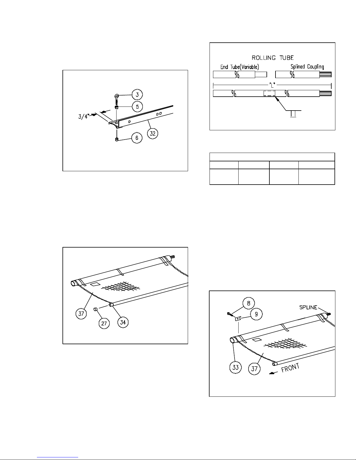
7. Install rod eye (3), nut (5), and locknut
(6) at front of latch plate (32) approximately 3/4" from end. See Fig. 4.
Fig. 4
8. Unfold tarp (37). Weld two halves of
1-1/8" fixed tube (34) (see Table 1 for
overall length). Insert tube in end of
tarp. Install end cap (27) in tube. See
Fig. 5.
270917-4
Fig. 6
270917-6
Table 1
OVERALL LENGTH
Model Fixed Tube Ridge Pole RollingTube "L"
672,674 160" 140 1/2" 167"
10. The rolling tube (33) and tarp (37)
must be flush as shown. Where straps
join tarp, drill 1/8" pilot holes through
tarp and tube. Install tube
U-clamps (9) with self-threading
screws (8) to secure tarp to tube.
See Fig. 7.
Fig. 5
9. Assemble splined coupling and 2"
rolling tubes as shown in Fig. 6 (see
Table 1 for length). Weld sections
together. Clean weld around tube to
prevent damage to tarp. Insert 2" tube
assembly (33) in tarp with spline to
rear. See Fig. 7.
270917-5
4-5
Fig. 7
270917-7
Page 68
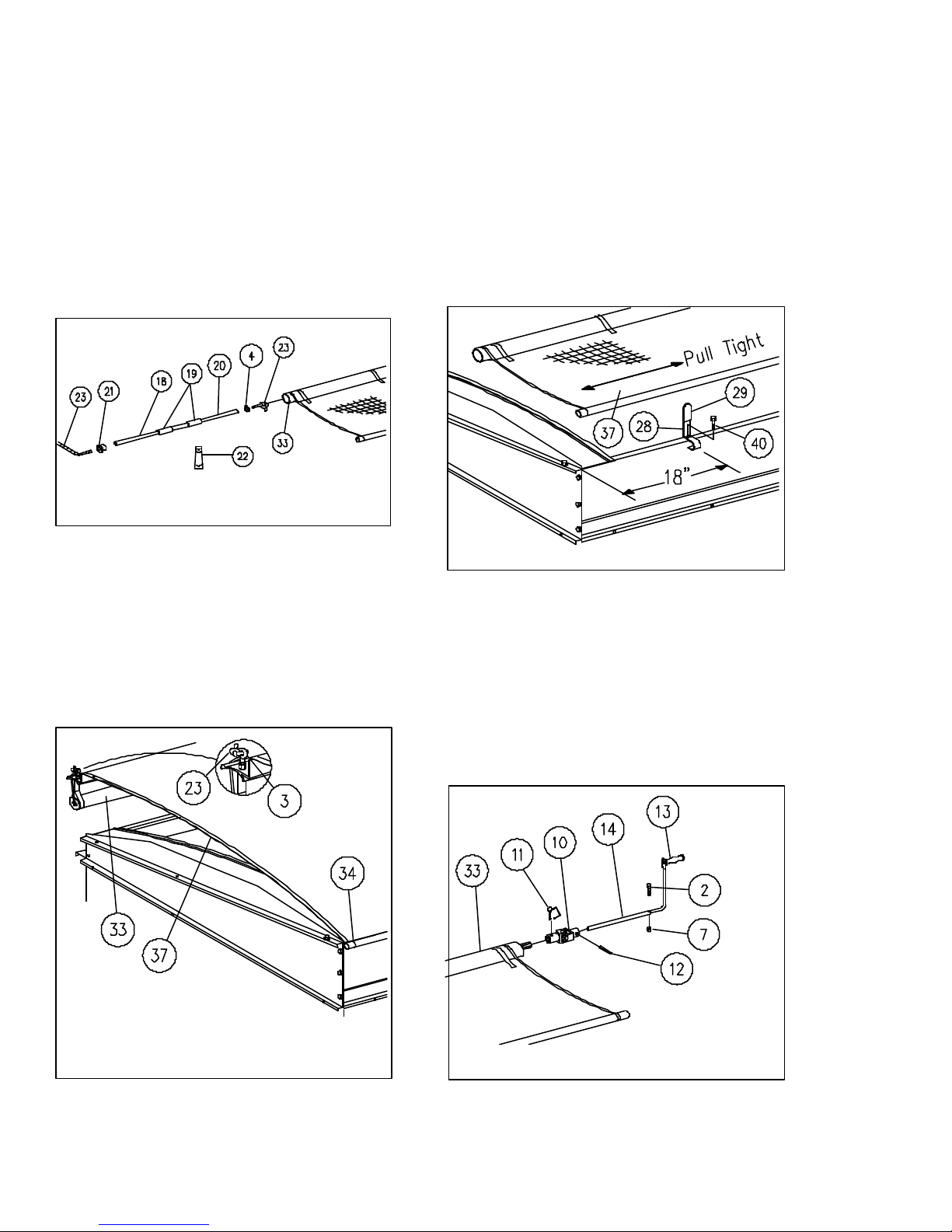
11. Assemble pvc pipes (18,19) and connectors (20) as required with plastic
adhesive (22). See Fig. 8.
12. Insert knotted stretch rope (23)
through flatwasher (4) and plastic tube
(18-20). Place these items as an
assembly into front of large rolling
tube (33) and tap retainer (21) into
rolling tube. See Fig. 8.
14. Assemble tarp (37) and stops with
caps, (28,29) to top of left hand side
boards with capscrews and nuts (40).
Note: With tension on tarp, install
center stop first. Align tarp and install two outer stops. The tighter the
tarp, the better the wear. See Fig.
10.
Fig. 8
13. Lift tarp (37) with tubes (33,34) onto
top of left side boards. See Fig. 9.
270917-8
Fig. 10
15. Insert U-joint (10) over splined coupling (part of 33) and secure with wire
pin (11). Place handle extension
(14) into U-joint and secure with spring
pin (12). Insert handle (13) into extension (14) and secure with capscrew
(2) and locknut (7). See Fig. 11.
270917-10
Fig. 9
270917-9
Fig. 11 270917-11
4-6
Page 69
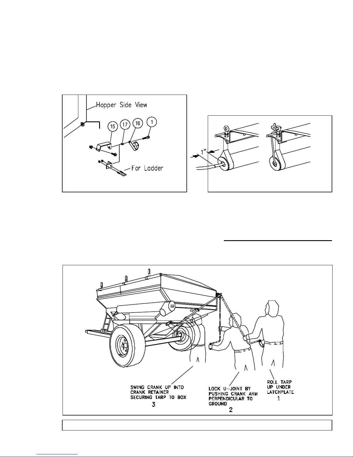
16. Install crank standoff (15) to wagon or
cart. OPTIONAL: Install crank standoff with U-bolts to rear ladder.
Attach crank retainer (16) and bushing (17) with capscrew (1). See Fig.
12.
17. Unroll tarp and let hang over edge of
box. Pull stretch rope until all slack
has been removed from the roll return assembly. Mark the stretch rope
1" from the aluminum cap. Thread
the stretch rope through the eyebolt
until the mark passes through. Tie a
knot on the mark. Cut off excess
stretch cord and melt frayed ends.
See Fig. 13.
Fig. 12
270917-12
18. Tighten tarp by holding the crank firmly
with both hands and roll the main tarp
tube counter-clockwise up under the
latch plate. Next, bring the crank
handle down perpendicular to the
ground. Continue by lifting it up into
the crank retainer. Note: a slight bow
in crank tube should indicate adequate
tension.
Fig. 13
270917-13
Repeat step 18 while adjusting the
splined shaft and U-joint one tooth at
a time to achieve 40-60 pounds of
tension at the handle end of the crank.
19. Install warning decal near the crank
retainer.
Failure to install the decal and follow the instructions will
void warranty.
Fig. 14
IMPORTANT: CONTINUALLY MONITOR TARP TENSION OR PREMATURE TARP WEAR WILL OCCUR !
250933
4-7
Page 70
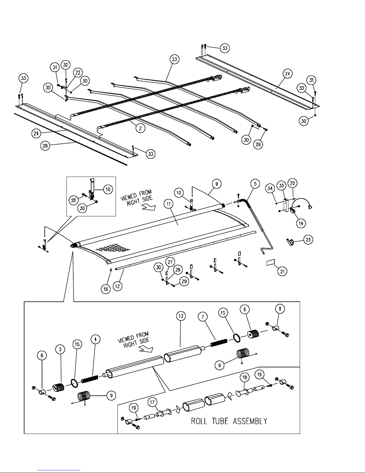
MODELS 672 & 674 - TARP
234913
• 04-01-02
4-8
Page 71

MODELS 672 & 674 - TARP
ITEM DESCRIPTION PART NO. QTY. NOTES
1 Tarp Kit w/End Caps 250399 1 Includes Items 1 Thru 35
2 Tarp Ratchet / Ridge Strap 9003098 2 Repl. 105819
3 Nylon Spool, Front (Red) 9003549 1 Repl. 105825
•
•
4 Tarp Spring, Front (Red) 105826 1
5 Crank, Roll-Over Tarp 9003140 1
6 Nylon Spool, Rear (Black) 9003550 1 Repl. 105893
•
•
7 Spring, Rear (Black) 105894 1
8 PVC Spacer w/Fasteners 105998 2 1 5/16" Dia.
9 Cable w/Ball & Barrel Ends - 172" 9003551 2 Repl. 106003 (151 1/2" Lg.)
•
10 Ratchet Strap 106042 2
11 Tarp, Fabric 9003178 1 152 x 156"
12 Mounting Tube, Stationary 9003181 1 1 x 152"
13 Roll Tube, Aluminum 9003180 1 3 x 162"
14 Crank Tube Holder w/Pin & Hdwe 9003096 2
15 Rubber Ring 97166 2
16 Pop Rivet, 3/16 Large Flange 97172 4
17 Cartridge Tube (Red ) - Front 9003084 1
•
18 Cartridge Tube (Black) - Rear 9003085 1
•
19 Bolt 9003086 2
20 Self-Tapping Screw, 3/8 x 1 96972 8
21 Decal, "Adjust Ratchets" 105876 2
22 Bracket 250881B 4
23 Bow Weldment 251211B 4
24 Cap, Front 250880B 2 142 7/8" Lg.
25 Crank Tube Holder 96970 1
26 Stop 266689B 4
27 Cap, Plastic 9003078 4
28 Trimlok 9000787-139 1
Fastener Kit 251178 1 Includes Items 29 Thru 34
29 Large Flange Screw, 3/8-16 x 1 91262 4
•
30 Large Flange Nut, 3/8-16 91263 26
31 Large Flange Screw, 3/8-16 x 3/4 95585 12
32 Carriage Bolt, 3/8-16 UNC x 1 9388-051 10
•
•
33 Self-Threading Screw, 1/4-20 x 3/4 9512 8
34 Locknut, 3/8-16 9928 2
35 Channel Bracket 251132B 1
• 04-01-02
4-9
Page 72
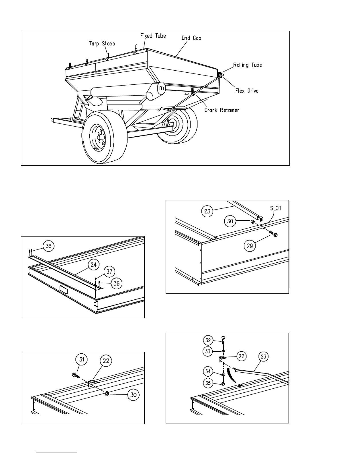
TARP INSTALLATION
Fig. 1
1. Install the side board extensions to
the box. See page 1-6.
2. Assemble the end caps (24) to the
front and rear side boards with 3/8 x
3/4 flange screws and nuts (37).
Fasten to right and left side boards
with 1/4 x 1 self-threading screws
(36) See Fig. 2.
Fig. 2
3. Assemble the bow brackets (22) to
the right side panel or side board with
3/8 x 3/4" flange screws (31) and
flange nuts (30). See Fig. 3.
251915-2
251916
4. Insert the bows (23) into the slots in
the left side board. Retain with
3/8 x 1" flange screw (29) and flange
nut (30). See Fig. 4.
Fig. 4
5. Position the bows under the right side
brackets (22) and retain with 3/8 x 1
carriage bolts (32), flatwashers (33),
lockwashers (34) and nuts (35). See
Fig. 5.
251915-4
Fig. 3
251915-3
Fig. 5 270917-5
4-10
Page 73
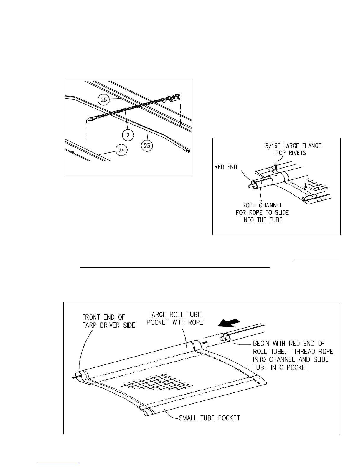
6. Attach the hooks on each end of the
two ridge strap assemblies to the holes
in the center of the end caps. Run the
straps over the top of the bows (2).
Draw the straps snug tight with ratchets. Do not overtighten. See Fig. 6.
8. Insert the small 1" tube by sliding it
into the small pocket of the tarp. Align
the holes at one end and fasten with
a rivet. At the other end, pull on the
tarp by hand to stretch it until the
holes match. Install remaining rivets.
See Fig. 8.
INSTALLATION TIP:
Tarp is designed to be stretched the length
of the tube to reduce wrinkling. For easier
assembly apply liberal dusting of baby powder on tube and inside of tube pockets
before sliding tubes in pockets.
Fig. 6
251915-6
7. (2-person operation) On a clean
floor, lay the tarp out flat with the rope
in the large pocket to the
bottom, (raw edge of the hems and
pockets down) and the exterior side
facing up. There is a hole about
4 1/2" from each end of the roll tube
Fig. 8
and a hole about 1 1/2" in on each
end of the large pocket.
Match the roll tube channel with the sewn-in rope on the tarp pocket. The tube holes
and tarp holes must be on the same side of the rope to line up. Slide the tube into the
tarp pocket, making certain that the rope is fully engaged in the rope channel on the
tube. Align the holes at one end, insert the large flange rivet and fasten. On the other
end, by hand, pull on the tarp to stretch it until the holes on the tube and tarp line up,
then insert rivet and fasten. See Fig. 7 & 8.
251915-7
Fig. 7
• 04-01-02
251915-7
4-11
Page 74
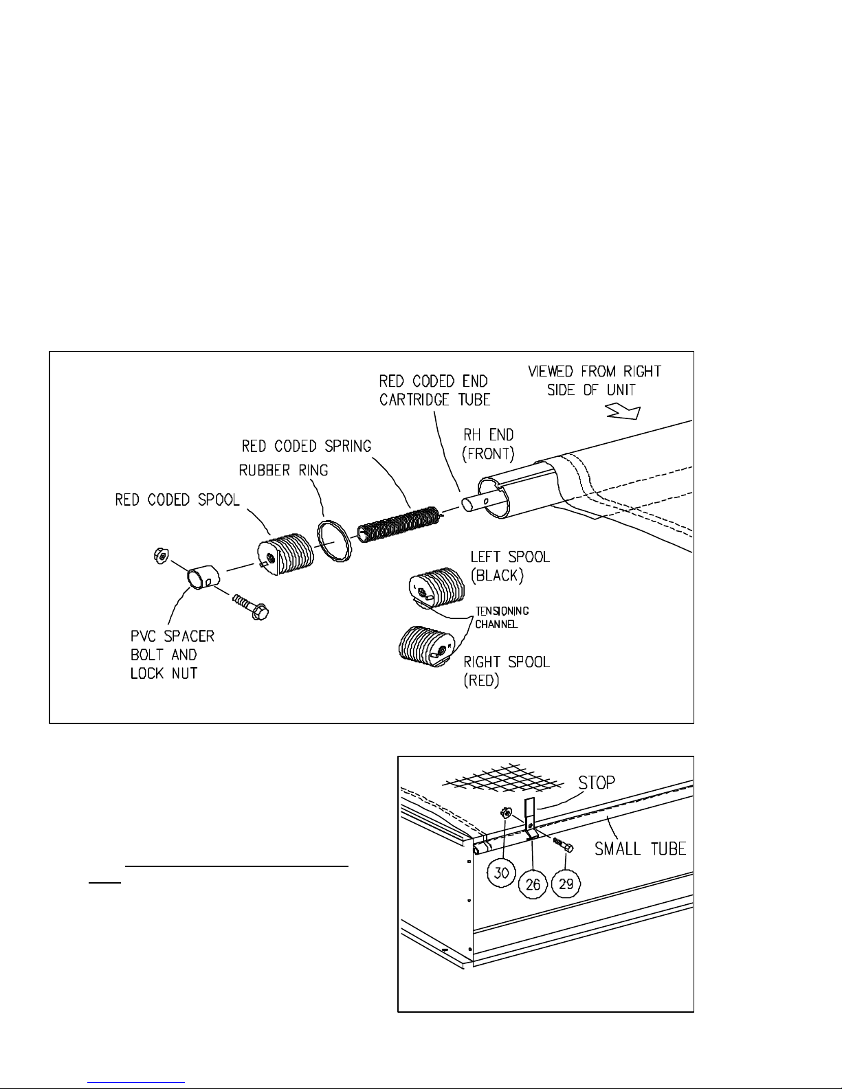
ATTACHING SPOOLS TO ROLL TUBE
A. REAR SPOOL (BLACK)
The inside of the spools are pre-greased
for use and color coded for assembly.
9. Slide the rubber ring on the roll tube
about 2 inches. Then insert the black
end of the spring into the black spool
so the spring tab extends through the
small hole in the spool. Slide the
spring with spool over the black end
of the roll tube so that the cartridge
tube extends through the center hole
of the spool.
To ensure the spring tab fully
engages in the tube cartridge, turn
the spool COUNTERCLOCKWISE
about one inch and push. To fasten
the spool to the cartridge tube, slide
the PVC spacer until holes align, then
bolt with a 5/16 x 1 3/4 bolt and lock
nut. See Fig. 10.
B. FRONT SPOOL (RED)
10. Install the front spool and related components in the same manner as the
rear. Then turn CLOCKWISE and
push on. Slide the PVC spacer on
and temporarily bolt on. See Fig. 10.
Fig. 10
C. ROLL TARP ASSEMBLY
11. Hand roll the tarp into open position.
Place the 1" stationary tube side of
the tarp on top of the left side of the
box, centered from front to back of
box. BE CAREFUL NOT TO LET THE
TARP ROLL OFF OF THE BOX.
Assemble the tarp and stops (26) (with
caps) to the left side boards with
flange screws and flange nuts.
4-12
Fig. 11
251915-10
251915-11
• 04-01-02
Page 75
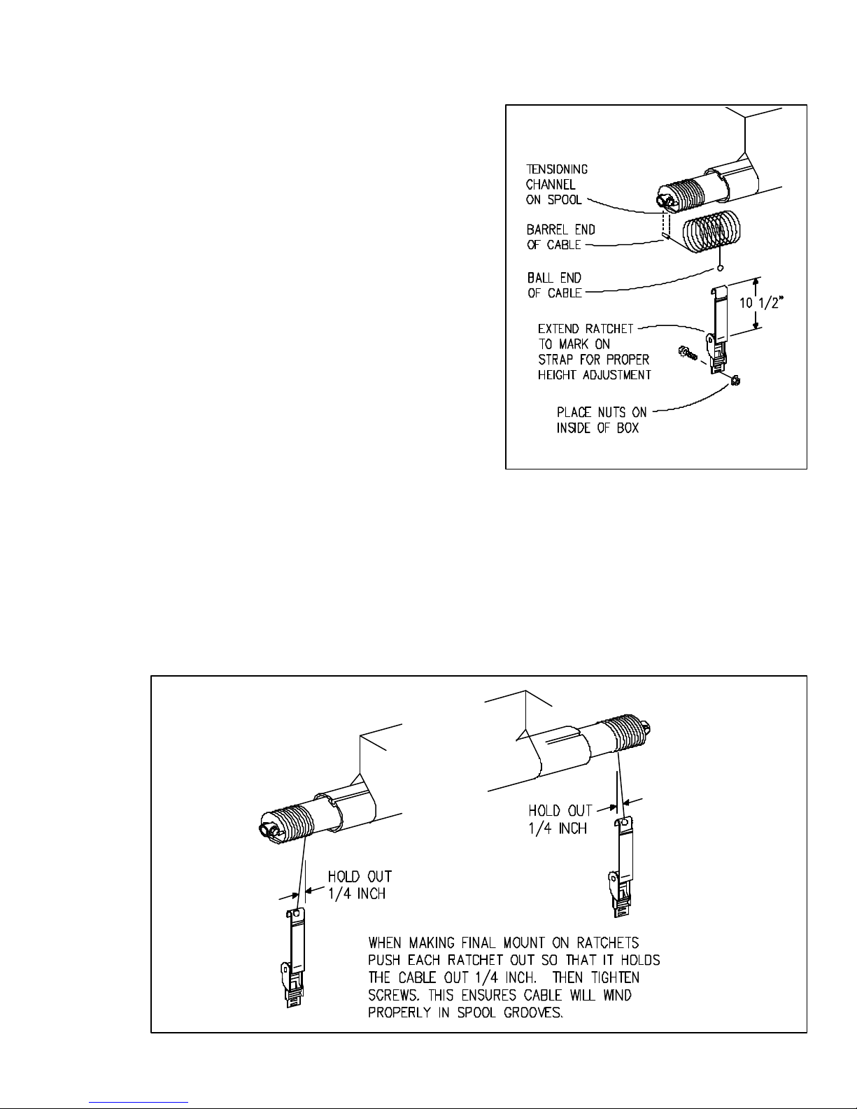
ATTACHING CABLES AND RATCHETS
A. WRAPPING CABLE
12. With the tarp hand rolled to the covered position, attach the barrel end of
the cable to the barrel groove on the
spool.
13. Now wrap the cable around the spool.
Be sure the cable follows the grooves
while doing so. If done correctly, the
cable will have fully wrapped the spool
with barely an inch hanging down.
Attach ball end of the cable to the
ratchet strap hook. See Fig. 12.
Fig. 12
B. MOUNTING RATCHETS
14. When the cable is wound on the spool and attached to the ratchet hook, pull down on
the ratchet with one hand, and with the other hand, activate the release on the ratchet
to extend the strap to the mark on the strap. By doing this you will have set the ratchet
to the correct mounting height. If for some reason you cannot mount the ratchet at this
height, lower it slightly to the closest point for mounting. Attach the ratchet to the side
of the box at this level. The ratchet must be securely mounted to the side of the box.
Drill 5/16 holes and use 3/8 x 1 self-threading screws. Before tightening, adjust
brackets to hold cables at an angle as shown. See Fig. 13.
251915-12
Fig. 13
251915-13
4-13
Page 76
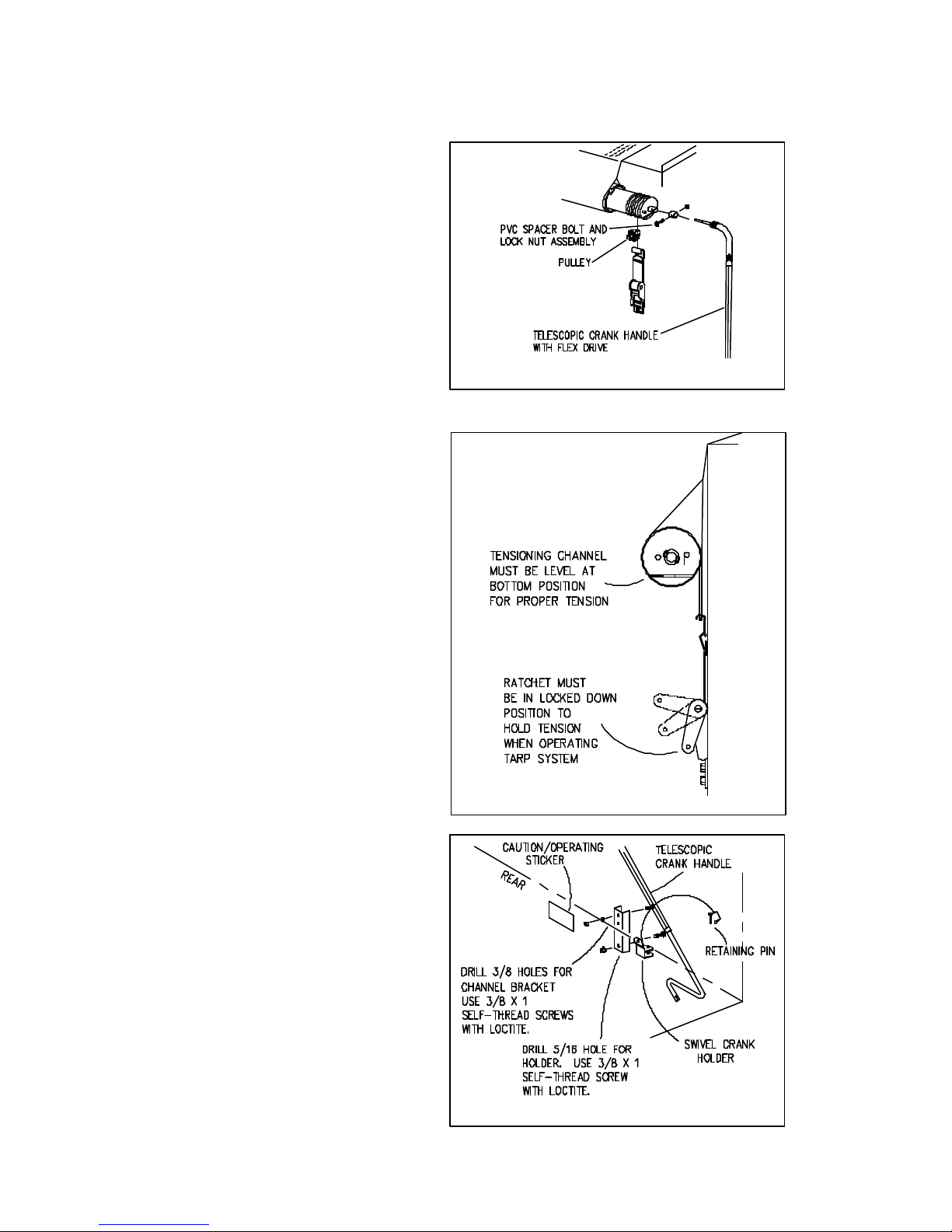
HAND CRANK HANDLE
INSTALL FLEX DRIVE
15. With both ratchets firmly mounted to
the side of the box, remove the finger
tight nut and bolt that holds the PVC
spacer on at the rear (red) end of the
roll tube. Holding the flex drive end
of the handle parallel to the roll tube,
slide the shaft into the end of the
tube protruding from the spool and
align the holes on the handle shaft
and the PVC spacer with the holes
on the tube. Reinsert the bolt and
tighten with the lock nut. See Fig. 14.
CABLE TENSION
DETERMINING TENSION
16. Cable tension is easily determined by
the position of the tension channel on
the front and rear spools.
Fig. 14
251915-14
As tension is applied with the ratchet,
the spool turns. Watch the tensioning
channel on the side of the spool -
proper tension is achieved when
the tension channel is level at the
bottom. See Fig. 15.
INSTALLATION TIP:
Tighten the ratchet an additional two
clicks past level. Then open and close
tarp system approximately five times.
This allows cable to seat in spool
grooves and tarp material to pull snug.
Now check tension channel. It should
be in the level position. Periodically
check tension level during use.
17. Locate the channel bracket holes just
above the box fold line, centered on
the box. Drill two 3/8" holes and use
screws with loctite, flatwashers, and
nuts to mount the channel bracket.
See Fig. 16. Attach the swivel crank
holder with fasteners to the channel
bracket.
Fig. 15
251915-15
Locate the operating decal near the
handle as shown. Clean the surface
and apply the sticker permanently.
4-14
Fig. 16
251915-16
Page 77

TARP OPERATING SAFETY INFORMATION
nnnnnn
Always use adequate caution when operating tarp.
n
Make sure tarp is open before unloading or loading.
n
Make sure nobody is on or near the tarping system before and during operating.
Do not operate tarp with box hoisted in an elevated position.
n
If tarp is covered with snow, it is important to remove snow before operating.
n
End caps must be free from grain that may be piled on them. Grain should not be heaped
n
higher than end caps.
Tarp may be fully opened or completely closed while in transit. However, the closed position
n
is recommended.
Instruct everyone who will operate this tarp the correct procedures of doing so, or have them
n
read this entire manual.
Insert snap pins whenever removing or placing crank in holders.
n
INSPECTION AND MAINTENANCE
Periodic preventive maintenance should be practiced. Inspect tarp and hardware often for
nnnnnn
abrasions or loosened bolts that may need adjustment and/or repair. Check cables for wear
and adjust tension whenever needed. Cable spools are factory greased, but over time and
use may require re-greasing.
If installed correctly, tarp should always operate as well as when first installed. If tarp does
n
not pass this simple inspection, make all appropriate repairs or adjustments immediately
before serious damage occurs.
OPERATION
Remove the retaining pin from the crank holder. Using both hands, carefully remove the
crank from the holder. Extend the crank handle assembly to a comfortable position at the rear
of the box. Roll the tarp to the desired location - fully open or fully closed position. Place the
crank in the holder and re-insert the retaining pin.
4-15
Page 78

TARP TROUBLE SHOOTING GUIDE
PROBLEM
CABLES DO NOT STAY IN GROOVES ON
NYLON SPOOLS WHEN OPERATING.
TARP DOES NOT WIND SMOOTH. BINDS
ON ONE END OR BOTH ENDS.
CANNOT FULLY OPEN TARP.
SOLUTION
1. Cable ratchets may need offset
adjustment.
2. Cable tension may need adjustment.
3. Spools may be binding on roll tube, need
cleaning and regreasing.
1. Spools may be binding on roll tube, need
cleaning and regreasing.
2. Cable tension may be too loose. Check
level of tension channels for proper
tension.
3. Tarp has been altered or improperly
repaired.
TARP SAGS IN MIDDLE AREAS.
HOLES OR TEARS IN TARP.
1. Bows may be bent, or adjusted too low.
2. Missing or loose ridge strap.
3. Cable tension may be too loose. Check
level of tension channels for proper
tension.
1. Consult your local dealer for repairs.
2. Order tarp repair kit from dealer.
3. When new tarp or parts are needed
always replace with original parts.
• 04-01-02
4-16
Page 79

NOTES
4-17
Page 80
MEMBER
FEMA
FARM EQUIPMENT
MANUFACTURERS
ASSOCIATION
TCMANUALS\PM5\250475-092995-1\REV092203\122904-2
 Loading...