

Page 1

Microlight M400
Pilot Operating Handbook
Issue 1
This Manual belongs to aircraft reg : ________________________
Breezer Type : Breezer M400____________
Serial No. : ________________________
Owner/operator : ________________________
Date : ________________________
Manufacturer: Ascent Industries Ltd. (Trading name Breezer Aviation
used throught this manual)
This handbook should be kept with the aircraft.
Page 2

Breezer M400 UK-22 Pilot Operating Handbook iss 1
Type
Production
Serial Number:
Destination and year of
production (if known)
Fuselage
Breezer Nose Wheel
BREEZER
AVIATION
Ascent Industries
Luke’s Field
Kent
Engine
ROTAX 912 ULS
BOMBARDIER
-ROTAX
GMBH
AUSTRIA
PROPELLER
DUC Swirl
1730 mm (100hp)
Or Woodcomp
Propuls AE174
DUC Helices,
France
Woodcomp
CZ
B
l
a
d
e
S/N’s
1
.
2
.
3
.
Parachute
Safety
system
BRS 6 1050
BRS
S/N
Manufacturer
Ascent Industries Ltd T/A BREEZER AVIATION
The Hangar
Wanshurstgreen Farm,
Battle lane,
Marden,
Kent, TN12 9DF
Breezer Aviation is a trading name of Ascent industries Ltd. Company registration nr 7731403
The Breezer aircraft design has been assessed by the BMAA on behalf of the CAA against BCAR
Section S (supplemented with appropriate requirements from CS-VLA). The aircraft is a Type
Approved Microlight under the ultimate supervision of the CAA.
2
Page 3

Breezer M400 UK-22 Pilot Operating Handbook iss 1
No.
Description
Page
Date
Signature
1
Initial Issue
All
9th January
2018
Amendment status
3
Page 4

Breezer M400 UK-22 Pilot Operating Handbook iss 1
Contents
Manufacturer ................................................................................................................................................ 2
1 General ..................................................................................................................................................... 6
1.1 Introduction ................................................................ ..................................................................... 6
I.2 Certification basis ................................................................................................................................ 7
I.3 Notes / Warnings ................................................................................................................................. 7
I.4 Description /Technical data .................................................................................................................. 7
3 - view Breezer M400 UK ............................................................................................................................... 9
II Limitations .......................................................................................................................................... 9
II.1 Introduction ................................................................ ..................................................................... 9
II.2 Airspeed limitations ....................................................................................................................... 11
II.2.1 Airspeed calibration: ...................................................................................................................... 11
II.3 Airspeed indicator markings........................................................................................................... 11
II.4 Power plant........................................................................................................................................ 12
II.4.1 Engine ................................ ................................................................................................ ........... 12
Operating weights and loading (occupants, baggage, fuel, ballast) ............................................................... 13
II.4.2 Lubrication / Coolant ..................................................................................................................... 14
Coolant: ..................................................................................................................................................... 14
Designation BASF Glysantine G48 or similar ..................................................................................... 14
II.4.3 Propeller ................................................................................................................................ ............ 14
II.5 Weight / Centre of gravity .................................................................................................................. 14
I.6 Manoeuvre limits ............................................................................................................................... 14
II.7 Fuel limitations .............................................................................................................................. 15
III Emergency Procedures ....................................................................................................................... 15
III.1 Introduction ................................................................................................................................... 15
III.2 Engine failure ................................................................................................................................ 15
III.2.1 – On the ground ............................................................................................................................... 15
III.2.2 – Short after Take off ................................................................ ....................................................... 15
III.2.3 – in flight ......................................................................................................................................... 15
III.3 Fire................................................................................................................................................ 15
III.4 Glide ............................................................................................................................................. 16
III.5 Forced landings ............................................................................................................................. 16
III.6 Stalls / Spins .................................................................................................................................. 17
III.7 Other emergencies ......................................................................................................................... 17
III.8 Recovery system ............................................................................................................................ 18
IV Normal procedures ............................................................................................................................. 18
IV.1 Introduction ................................................................ ................................................................... 18
IV.2 Pre-flight inspection ....................................................................................................................... 18
4
Page 5

Breezer M400 UK-22 Pilot Operating Handbook iss 1
Walk-around inspection .............................................................................................................................. 18
IV.3 Normal procedures......................................................................................................................... 20
IV.4 Check list ...................................................................................................................................... 23
V Performance ........................................................................................................................................... 23
V.1 Introduction ................................................................................................................................... 23
V.2 Airspeeds ...................................................................................................................................... 23
V.2.1 Load limits .................................................................................................................................... 23
V.2.2 Take-off and landing distances ....................................................................................................... 23
V.2.3 Rate of climb ................................................................................................................................. 23
V.3 Wind speeds and service ceiling ..................................................................................................... 23
V.4 Range ............................................................................................................................................ 24
V.5 Noise emission measurements ........................................................................................................ 24
VI Weight and Balance ........................................................................................................................... 24
VI.1 Introduction ................................................................ ................................................................... 24
VI.2 Weighing (completed at first factory build) .................................................................................... 24
VI.3 Weighing report example ............................................................................................................. 27
VII Aircraft and systems description ......................................................................................................... 27
VII.1 Structure ........................................................................................................................................ 27
VII.2 Flight controls ............................................................................................................................... 27
VII.3 Instrument panel example .............................................................................................................. 28
VII.4 Landing gear.................................................................................................................................. 28
VII.4.1 Brake system ............................................................................................................................. 28
VII.4.2 Adjustable rudder pedals ............................................................................................................ 28
3.6 Adjustable rudder pedals for the pilot can be ordered as an option................................................... 28
VII.5 Seats and safety harnesses .............................................................................................................. 29
VII.6 Baggage compartment ................................................................................................................... 29
VII.7 Canopy .......................................................................................................................................... 29
VII.8 Engine ........................................................................................................................................... 29
VII.9 Fuel system ................................................................................................................................... 30
VII.10 Electrical system ....................................................................................................................... 31
VII.11 Pilot-static system...................................................................................................................... 31
VII.12 Avionics .................................................................................................................................... 31
VII.13 Placards ......................................................................................................................................... 31
Warning placard - flight manoeuvres: On the instrument panel .................................................................... 32
VIII Handling, service and maintenance..................................................................................................... 34
VIII.1 Introduction ............................................................................................................................... 34
VIII.2 Maintenance intervals ................................................................................................................ 34
VIII.2.1 Changes / Repairs .......................................................................................................................... 34
VIII.3 Ground handling ........................................................................................................................ 34
VIII.4 Cleaning and care ...................................................................................................................... 34
VIII.5 Special operating conditions ...................................................................................................... 34
IX Equipment ......................................................................................................................................... 34
5
Page 6

Breezer M400 UK-22 Pilot Operating Handbook iss 1
IX.2 Recovery system ............................................................................................................................ 35
IX.3 Optional equipment ....................................................................................................................... 35
X Appendix ................................................................................................................................................ 36
X.1 Check list ...................................................................................................................................... 36
X.2 Control surface deflections and weights ......................................................................................... 37
X.3 Electrical circuit plan example. ...................................................................................................... 38
Each Breezer will be delivered with its own circuit diagram to cater for any minor differences .................... 38
X.4 Recovery system installation .......................................................................................................... 39
1 General
Read this Handbook carefully before your first flight!
1.1 Introduction
This handbook contains the information required by airworthiness requirements to be furnished to the
pilot and supplemental data supplied by the manufacturer. It has been compiled to supply pilots and
instructors with all the necessary information to ensure the safe operation of this microlight aeroplane.
The handbook is based on the current standard-equipped version of the Breezer. Supplemental
equipment is usually not dealt with. Information on such optional equipment is provided by the
operating instructions issued by Breezer Aviation.
It is the responsibility of the operator of the aircraft to read the handbooks and operating instructions
and to familiarise him/herself with the aircraft, its engine and equipment, in particular with the special
characteristics of the Breezer M400. A record of all amendments is to be found in the front of this
manual.
To operate the aircraft the pilot must hold a suitable valid pilots license and ensure he/she has
appropriate familiarization on type. The aircraft is not to be flown unless it is registered, carries
registration markings in accordance with the requirements of the UK CAA, and has a Permit to Fly.
The aircraft is to be flown under daytime VFR. Flight into conditions other than VFR is extremely
dangerous and can result in serious injury or death.
It is recommended that the pilot understands flying the Breezer as it possesses characteristics that
are unique to microlight aircraft. These characteristics include low inertia, susceptibility to turbulence
and wind gradient and special engine considerations.
The safety of all occupants, the aircraft and persons on the ground are the sole responsibility of the
the Pilot in command. Do not operate this aircraft in a manner that would endanger the occupants, the
aircraft or persons on the ground.
The engine of this aircraft is not certified, and could fail at any time. For this reason it is
recommended NEVER fly over congested areas or other areas on to which a safe landing
cannot be made in the event of an engine failure. On cross country flights, ALWAYS keep an
emergency landing field in sight.
Changes to the control system, structure, wings, engine or any other part of the aircraft are prohibited
unless approved by Breezer Aviation or the BMAA. Any unautherised changes would invalidate any
permit to fly and as such would result in an insurance becoming null and void.
Any operating difficulties and equipment failures should be reported to Breezer Aviation.
6
Page 7

Breezer M400 UK-22 Pilot Operating Handbook iss 1
I.2 Certification basis
This aircraft is a Type Approved Microlight and was manufactured in accordance with BCAR Section
S airworthiness standards approved by the UK CAA.
I.3 Notes / Warnings
Notes and sections which are of particular importance to operation and flight safety are highlighted as
follows:
Note
Draws attention to information which is not directly related to the safe operation of the microlight
aircraft but which is important and to which attention should be paid.
Caution
Draws attention to methods, procedures or limits which must be followed to avoid short-term or longterm degradation of flight safety.
Warning
Draws attention to methods, procedures or limits which must be followed precisely to avoid immediate
or massive degradation of flight safety.
Note
Always prepare a cross-country flight with due diligence. Use all available sources of information, e.g.
NOTAMS, aviation authority bulletins, safety requirements. Even on short flights you should always
call up the current weather reports, notams and forecasts.
Caution
For fire safety reasons, smoking is prohibited on board.
Avoid flights in heavy turbulence or thermal winds. Should you be unable to avoid such areas,
reduce speed to Vno to avoid damage to the aircraft structure.
Keep well away from storm fronts. Make a precautionary landing if necessary.
I.4 Description /Technical data
The Breezer is a two-seat microlight aircraft with a conventional aluminium stressed skin structure.
It is a monoplane with a cruciform empennage arrangement, two side-by-side seats, tricycle landing
gear and flaps.
The Breezer is powered by a geared Rotax 912 carburetted engine
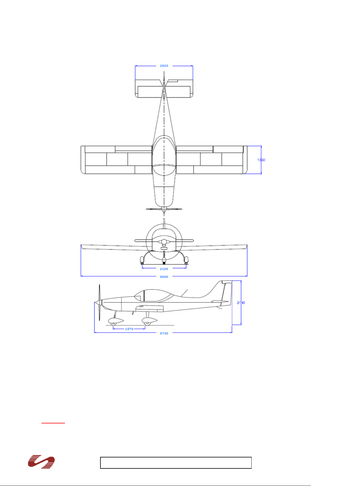
Fuselage:
Length 6.73 m
Height 2.14 m
Cockpit width 1.16 m
Wing:
Span 8.05 m
Wing depth 1.36 m
Wing area 10.95 m²
Wing aspect ratio 5.9
Wing profile type NACA 4414 mod.
Aileron:
Aileron area 0.93 m
2
7
Page 8

Breezer M400 UK-22 Pilot Operating Handbook iss 1
Flaps:
Area 1.14 m
2
Positions 0°/ 15° ±1,5°/ 25°±1,5° / 43° ±1,5°
Horizontal stabilizer:
Span 2.82 m
Stabilizer Area 2.40 m2
Elevator area 0.43 m²
Max. elevator deflection + 25° ±1°/ - 20° ±1°
Vertical stabilizer:
Span 1.24 m
Stabilizer area 0.82 m2
Rudder area 0.46 m2
Max. rudder deflection +/- 25° ±1°
8
Page 9
Breezer M400 UK-22 Pilot Operating Handbook iss 1
3 - view Breezer M400 UK
II Limitations
II.1 Introduction
This chapter includes operating limitations for the safe operation of the aircraft, its engine and
standard equipment. The limitations have been calculated and verified by tests.
Warning
The structure of this microlight aircraft is designed for a load limit of +4/-2g. Greater loads can
lead to catastrophic failure.
9
Page 10

Breezer M400 UK-22 Pilot Operating Handbook iss 1
Microlight aircraft are prohibited from performing aerobatic manoeuvres.
Turns with a banking angle of more than 60° are not allowed.
The never-exceed speed (VNE) must never be exceeded
Full control movements may be made up to the manoeuvring speed (VA). Above this speed,
no full or abrupt control movements should be made.
The maximum structural cruising speed (VNO) must not be exceeded except in smooth air and
then only with caution.
The flap limiting speed (VFE) must not be exceeded with the flaps extended.
Flight in known icing conditions is prohibited.
Flight operations should be terminated in very gusty winds or in wind speeds above 22 kts.
Providing the Breezer M400 is flown within the placarded limitations of pilot and baggage
weight, the aircraft will always be within the stated and tested CG limits.
The limitations are marked on the instruments in the cockpit. In addition, placards are mounted in the
cockpit on which the operating limitations are listed. These placards must not be removed at any time.
10
Page 11
Breezer M400 UK-22 Pilot Operating Handbook iss 1
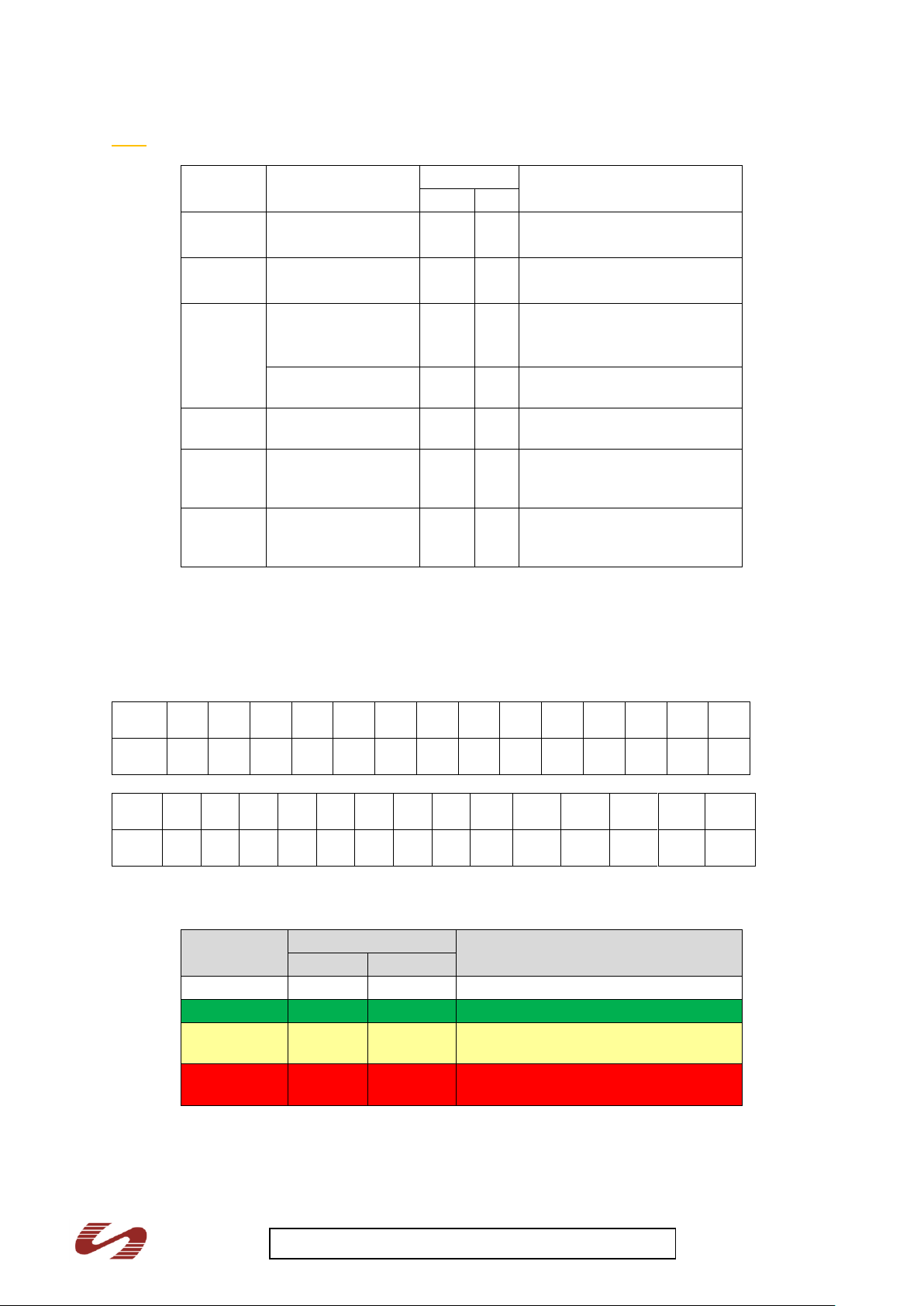
II.2 Airspeed limitations
Abbreviation
Term
IAS
Explanation
Mph
kts
VS0
Minimum speed;
stall speed
30
26
Minimum speed at 472,5 kg
(MTOW) and 45° flaps
VS
Minimum speed;
stall speed
35
30
Minimum speed at 472,5 kg
(MTOW) and 0° flaps
VFE
Maximum flaps
extended speed
78
68
Maximum speed with flaps
extended
3rd stage (advisory)
70
60
Maximum speed with 3rd
stage flap extended
VA
Maneuvering speed
86
75
No full or abrupt control
movement above this speed
Vno
Maximum structural
cruising speed
119
103
Operations must be conducted
with caution and only in
smooth air
VNE
Never exceed speed
150
130
Under no circumstances VNE
be exceeded; maximum
control deflections 1/3.
IAS
[Mph]
30
35
40
50
60
70
80
90
100
110
120
130
140
150
CAS
[Mph]
40
44
48
56
65
73
82
90
99
107
116
124
133
141
IAS
[Kts]
30
35
40
50
60
70
80
90
100
110
120
130
140
150
CAS
[Kts]
35
38
42
49
56
63
71
78
86
93
101
108
116
123
Marking
Indicated airspeeds
Explanation
Mph
kts
White arc
30 – 78
26 – 68
Full flap operating range
Green arc
35 – 119
30 – 103
Normal operating range
Yellow arc
119 - 150
103 – 130
Operations must be conducted with
caution and only in smooth air
Red line
150
130
Maximum speed for all operations
(VNE)
Note The airspeeds given in the table below are indicated airspeeds (IAS).
II.2.1 Airspeed calibration:
The following table shows indicated airspeed (IAS) and the calibrated airspeed (CAS), which is
corrected for installation errors.
II.3 Airspeed indicator markings
11
Page 12

Breezer M400 UK-22 Pilot Operating Handbook iss 1
II.4 Power plant
II.4.1 Engine
Engine manufacturer: BRP-Powertrain GmbH & Co KG
Engine model: 912 UL (59, 6 kW / 80 hp)
Description: 4-stroke, 4 cylinder horizontally opposed, spark ignition engine, one
central camshaft – push-rods – OHV
Liquid cooled cylinder heads
Ram air cooled cylinders
Dry sump forced lubrication
Dual breakerless capacitor discharge ignition
2 constant depression carburetors
Mechanical fuel pump
Prop drive via reduction gear with integrated shock absorber
Electric starter (12V 0,6 kW)
Integrated AC generator with external rectifier-regulator (12V 20A DC)
Gear: 2,27 : 1
Maximum take-off rpm: 5800 rpm (max. 5 minutes)
Maximum continuous rpm: 5500 rpm
Idle speed: ca. 1600 rpm
Take-off performance: 59,6 kW / 80 hp at 5800 rpm
Max. cont. performance: 58,0 kW / 78 hp at 5500 rpm
Fuel grade: Unleaded super, AVGAS 100LL
Acceleration: Limit of engine operation at zero gravity & in negative “G” conditions:
Max: 5 seconds at max. -0,5 g
Oil pressure: Max. 7 bar; Attention: For a short period admissible at cold start.
Min. 0,8 bar (12 psi) (below 3500 rpm)
Normal: 2,0 - 5,0 bar (29 - 73 psi) (above 3500 rpm)
Oil temperature: Max. 140°C (289°F)
Min. 50°C (120°F)
Normal operating temperature: ca. 90-110°C (190-230°F)
Engine coolant temperature: Max. 120°C (248°F)
Engine start, operating temp: Max. 50°C (120°F)
Min. -25°C (-13°F)
Fuel pressure: 0.15 - 0.5 bar (2.2 – 5.8 psi)
Note:
Exceeding the max. admissible fuel pressure will override the float valve of the carburetor.
Note:
The delivery pressure of an additional backing pump (e.g. electric standby pump) must not exceed 0,5
bar (4.4 psi) in order not to override the float valve.
12
Page 13

Breezer M400 UK-22 Pilot Operating Handbook iss 1
Engine model: 912 ULS ( 73, 5 kW / 99 hp)
Description: 4-stroke, 4 cylinder horizontally opposed, spark ignition engine, one
central camshaft – push-rods – OHV
Liquid cooled cylinder heads
Ram air cooled cylinders
Dry sump forced lubrication
Dual breakerless capacitor discharge ignition
2 constant depression carburetors
Mechanical fuel pump
Prop drive via reduction gear with integrated shock absorber and overload clutch
Electric starter (12V 0,6 kW)
Integrated AC generator with external rectifier-regulator (12V 20A DC)
Gear: 2,43 : 1
Maximum take-off rpm: 5800 rpm (max. 5 minutes)
Maximum continuous rpm: 5500 rpm
Idle speed: ca. 1600 rpm
Take-off performance: 73,5 kW / 99 hp at 5800 rpm
Max. cont. performance: 69,0 kW / 93 hp at 5500 rpm
Fuel grade: Unleaded super, AVGAS 100LL
Acceleration: Limit of engine operation at zero gravity & in negative “G” conditions:
Max: 5 seconds at max. -0,5 g
Oil pressure: Max. 7 bar; Attention: For a short period admissible at cold start.
Min. 0,8 bar (12 psi) (below 3500 rpm)
Normal: 2,0 - 5,0 bar (29 - 73 psi) (above 3500 rpm)
Oil temperature: Max. 140°C (289°F)
Min. 50°C (120°F)
Normal operating temperature: ca. 90-110°C (190-230°F)
Engine coolant temperature: Max. 120°C (248°F)
Engine start, operating temp: Max. 50°C (120°F)
Min. -25°C (-13°F)
Fuel pressure: 0.15 - 0.5 bar (2.2 – 5.8 psi)
Note:
Exceeding the max. admissible fuel pressure will override the float valve of the carburetor.
Note:
The delivery pressure of an additional backing pump (e.g. electric standby pump) must not exceed 0,5
bar (4.4 psi) in order not to override the float valve.
Operating weights and loading (occupants, baggage, fuel, ballast)
Max basic empty weight (for 472.5kg MAUW 100hp version) ..... 291.5 kg
Max. take-off weight ................................................................. 472.5 kg
Max. Landing weight ................................................................ 472.5 kg
Max. Fuel weight ...................................................................... 55 kg
Max. Baggage weight in baggage area ..................................... 15 kg
Number of seats ...................................................................... 2
Minimum crew weight ............................................................... 55 kg
Max crew weight per seat ......................................................... 105 kg
13
Page 14

Breezer M400 UK-22 Pilot Operating Handbook iss 1
II.4.2 Lubrication / Coolant
Coolant:
Designation BASF Glysantine G48 or similar
Mixture –coolant / water 50/50
Coolant capacity: ~ 3 l (0,8 US gal)
II.4.3 Propeller
All of the tested and approved propellers on this Microlight Breezer aircraft are optimized by the
aircraft manufacturer to ensure an optimum combination of climb and cruise performance.
II.5 Weight / Centre of gravity
Maximum take-off weight (MTOW) 472.5 kg
Maximum landing mass 472.5 kg
Empty weight 100HP 291.5 kg
Empty mass cf. weighing sheet, Chap. VI
Maximum loading mass - baggage 15 kg
Wing loading at MTOW 43,2 kg/m²
Power loading at MTOW 6.43 kg/kW
The reference level for all centre of gravity calculations is the canopy guide rail. The reference datum
(BP) is the wing leading edge. Refer to Chapter VI for more detailed information on the horizontal
alignment of the aircraft and the permissible centre of gravity range.
Operating centre of gravity range:
Forward: 258 mm / 19% MAC
Rearward: 448 mm / 33% MAC
Note
The pilot is responsible for ensuring that the maximum take-off mass is not exceeded. If additional
equipment is installed, the empty mass will increase accordingly. If equipment is removed, the empty
mass will decrease accordingly.
Warning
If the MTOW is exceeded, the Microlight Breezer will be over-loaded. This in turn will lead to
deterioration in flight characteristics and performance. It also reduces structural margins.
Exceeding the centre of gravity limits will detrimentally affect the controllability and stability of
the aircraft.
Providing the Breezer M400 is flown within the placarded limitations of pilot and baggage
weight, the aircraft will always be within the stated and tested CG limits.
I.6 Manoeuvre limits
The Breezer is designed for normal flight operations. This include any manoeuvres incidental to
normal flying and stalls (except whip stalls). Higher loads are not permitted.
Warning
All aerobatic manoeuvres including spins and whip stalls are prohibited.
Turns with bank angles exceeding 60° are not permitted
14
Page 15

Breezer M400 UK-22 Pilot Operating Handbook iss 1
II.7 Fuel limitations
Fuel tank capacity: 76 litres
Usable fuel: 74 litres
Fuel grade: Unleaded, UL91 or AVGAS 100LL
Note
When filling up using canisters or if the origin of the fuel is not known, use a funnel with a
water trap.
III Emergency Procedures
III.1 Introduction
The engines installed in the Breezer are not certified aviation engines. For this reason, engine failures
are common place. Keep this in mind and plan your flight so that you can safely perform a forced
landing at any time.
Note
The pilot can train how to react in an emergency. The following emergency procedures should be
committed to memory and emergency landing procedures should be trained frequently in flight.
III.2 Engine failure
III.2.1 – On the ground
Abort take-off roll - assuming enough runway is available ahead
1. Throttle idle
2. Brakes apply
III.2.2 – Short after Take off
Abort take-off
1. Push elevator control forward
2. Increase airspeed
3. Land straight ahead, only undertake small course directions to avoid obstacles.
Altitude and airspeed rarely suffice to perform the necessary 180° turn (if above 500 feet and
safe to do so) to return to the airfield.
Caution
Do not attempt such a turn below 500 feet AGL
III.2.3 – in flight
Look for an emergency landing area, pay attention to airspeed and, when possible, land into
the wind or up a slope. It is better to land long and perhaps roll into a hedge, than stall short of
the intended landing site. Fly the aircraft until it is stopped.
III.3 Fire
Engine fire on the ground
1 Fuel valve shut
2 Throttle full closed
3 Ignition switch both off
4 Master switch off
5 Evacuate the aircraft
Engine fire during take-off or in flight
1 Fuel valve shut
2 Throttle full closed
3 Ignition switch both off
15
Page 16

Breezer M400 UK-22 Pilot Operating Handbook iss 1
4 Master switch off
5 Perform an emergency landing
6 Evacuate the aircraft
Fire in the cockpit
1 Fuel valve shut
2 Ignition switch both off
3 Master switch off
4 Cabin heating off
5 Unlock canopy and open slightly
6 Perform an emergency landing
7 Evacuate the aircraft
III.4 Glide
1. Flaps retracted
2. Airspeed (IAS) 60 Mph
3. Glide ratio approx. 9.1
I.e. from an altitude of 1000 feet AGL, the gliding distance will be approximately 2 miles (no wind).
Note
The gliding distance increases with a tail wind and decreases with a head wind. Practise landing
without engine power under various conditions in order to reach perfection.
III.5 Forced landings
Forced landings are not only emergency landings undertaken due to critical technical defects, they
also include precautionary landings undertaken when the aircraft or its passengers are in danger due
to operational irregularities (e.g. rough engine operation) or deteriorating weather conditions.
Microlight pilots should react to technical defects or deteriorating weather conditions as follows:
1. Perform a forced landing or
2. Deploy the recovery system.
Warning
It is never wrong to deploy the recovery system; it can be used at relatively low altitudes (approx. 300
feet). However, it should only be deployed in true emergencies as the forces acting on the occupants
and the aircraft structure due to the descent speed can be much greater than those experienced
during a forced landing in an adequate emergency landing area.
In either case, the following checks apply:
1. Safety belts tighten and secure
2. Radio transmit emergency call (if time to do so)
3. Fuel valve shut
4. Ignition switch both off
5. Master switch off
The following steps should be taken when landing with a flat main tyre:
1. Full flaps in landing position during finals
2. Touchdown on the good main tyre first on the side of the runway away from the defect tyre so
as to make sure that the aircraft will remain on the runway during directional alterations made
necessary by the effects of the flat tyre.
3. Maintain directional control using the brakes and rudders.
16
Page 17

Breezer M400 UK-22 Pilot Operating Handbook iss 1
III.6 Stalls / Spins
Loss of control
Measures
Elevator
Control altitude and speed using
elevator trim
Aileron
Lower at least 2 stages of flap - use
rudder to turn and aileron trim
Rudder
Hold direction using ailerons
Stalls
Light buffeting will be experienced as the aircraft approaches its stall speed. At speeds below 50Mph,
the control forces will get lighter and feel “sloppy”.
A stall in level flight (slip ball centred) with flaps retracted is preceded by light buffeting. Usually the
aircraft will pitch down, in gusty weather it may have a slight tendency to drop one wing. Stall
characteristics with flaps extended are similar to those with flaps retracted and may be described as
docile or benign. Loss in altitude during stalling with maximum take-off mass is approximately 300
feet.
Stalling in a turn is preceded by light buffeting before the aircraft tends to roll out of the turn and
resume level flight. The aircraft shows no tendency to drop the wing on the inside of the turn. Loss in
altitude during a stall in a turn with maximum take-off mass is approximately 300 feet.
Spins
Intentional spins are prohibited in the Breezer. Given the cues associated with the onset of the stall as
described above, inadvertent spins are extremely unlikely to occur in this aircraft. However should an
inadvertent incipient spin occur, the following recovery procedure should be used:
1. Throttle idle
2. Rudder neutral
3. Aileron neutral
4. Elevator neutral
Should the incipient spin recovery not stop the spin then:
5. Throttle idle
6. Rudder progressively apply up to full rudder opposite to direction of rotation
7. Aileron neutral
8. Elevator progressively move the stick forward until the aircraft recovers
After rotation has ended, make a smooth recovery of the aircraft.
Warning
Too abrupt recovery could lead to overloading the aircraft structure. A too gentle recovery could lead
to VNE being exceeded and thus result in structural damage.
III.7 Other emergencies
Loss of controls
Should one of the controls be lost, flight may be continued using the remaining controls and engine
power to compensate for the loss. The following table shows how the various controls may be
compensated:
The following conditions must prevail when attempting a forced landing with defective controls:
The controls are not blocked in a non-neutral position
Smooth air
Large suitable landing area
Otherwise: Deploy the recovery system!
17
Page 18

Breezer M400 UK-22 Pilot Operating Handbook iss 1
Loss of alternator
If the voltmeter falls below 12 volt, the battery will not be re-charging. The alternator warning light will
illuminate when this defect occurs. The following steps should be taken when the alternator fails:
1. Switch off all electrical equipment not essential for safe flight operations
2. Land at the next airfield.
III.8 Recovery system
There is no standard rule as to when the recovery system should be deployed. The decision to deploy
is solely dependent upon the level of danger experienced by the pilot. At low altitude it is, however,
important to make a quick decision to ensure that the recovery system will operate safely. A
dangerous situation experienced at high altitudes gives the pilot more time to take his decision. The
recovery system should be deployed as follows:
1. Ignition switch both off
2. Fuel valve shut
3. Legs pull towards you
4. Release lever pull
5. Canopy unlock
6. Before landing brace, head on chest
7. After landing release safety belts and evacuate the aircraft immediately
Caution
A pull force of 12 kg is required to operate the release lever - if necessary, pull hard with both hands!
Warning
Secure the recovery system against unintentional deployment on the ground by inserting the
safety pin
Remove the safety pin before each flight - it could be too late during flight
Before deploying the recovery system, shut down the engine - in an uncontrollable situation,
the propeller could sever an attachment strap when the parachute opens.
IV Normal procedures
IV.1 Introduction
This chapter provides check lists and procedures for normal operation of the Breezer. Normal
procedures associated with optional systems can be found in Chapter IX.3.
IV.2 Pre-flight inspection
A pre-flight inspection should be undertaken before each flight. It is for your own safety and all points
should be carried out methodically. In this way, small defects may be discovered resolved.
Cabin control
a. Aircraft papers check
b. Check list available
c. Ignition key removed
d. Master switch off
e. Ignition key off
f. Amount of fuel sufficient for the planned flight
g. Throttle idle
h. Foreign body check complete
i. Controls moving without restriction
j. Baggage stored and secure
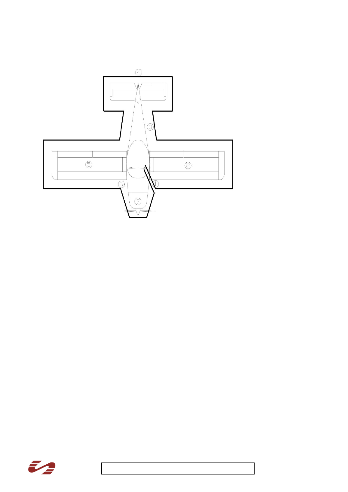
Walk-around inspection
Visually inspect the general condition of the aircraft, i.e. check the following positions for damage
(deformation, cracks), excessive play and freedom of movement of the control surfaces, correct
18
Page 19
Breezer M400 UK-22 Pilot Operating Handbook iss 1
attachment points and general good condition. Also check the ground and firewall for signs of engine
leakage (brake fluid, oil, coolant)!
1. Left main landing gear
(1) Landing gear strut visual inspection
(2) Landing gear attachment visual inspection
(3) Wheel fairing (if installed) visual inspection
(4) Tyre pressure check
(5) Tyre, wheel, brakes visual inspection
2. Left wing
(1) Wing skin visual inspection
(2) Wing tip, mass balance visual inspection
(3) Pitot tube bore-hole free, clean
(4) Strobe light (if installed) visual inspection
(5) Aileron visual inspection
(6) Flaps visual inspection
3. Fuselage
(1) Skin visual inspection
(2) Recovery system, attachment straps visual inspection
(3) External items visual inspection
4. Empennage
(1) Stabilisers and control surfaces visual inspection
(2) Trim surfaces visual inspection
5. Right wing
(1) Wing skin visual inspection
(2) Flaps visual inspection
19
Page 20

Breezer M400 UK-22 Pilot Operating Handbook iss 1
(3) Aileron visual inspection
(4) Wing tip, mass balance visual inspection
(5) Strobe light (if installed) visual inspection
6. Right main landing gear
(1) Landing gear strut visual inspection
(2) Landing gear attachment visual inspection
(3) Wheel fairing (if installed) visual inspection
(4) Tyre pressure check
(5) Tyre, wheel, brakes visual inspection
7. Front fuselage
(1) Upper cowling remove
(2) Oil level check
(3) Coolant level check
(4) Fuel visual inspection
(5) Cowling visual inspection
(6) Air inlets no blockage
(7) Propeller visual inspection, secure
(8) Gearbox turn via propeller check for unusual noises
(9) Spinner visual inspection
(10) Nose landing gear visual inspection
(11) Tyre and wheel visual inspection
(12) Wheel fairing (if installed) visual inspection
(13) Tyre pressure check
Note
The following points should be checked in addition to the steps listed under 7, as daily inspections
prior to the first flight of the day.
8. Front fuselage
(14) Fuel tank drain sample to check for water
(15) Engine mount visual inspection
(16) Exhaust system visual inspection
(17) Lubrication and fuel lines visual inspection
(18) Electric system and Bowden cables visual inspection
(19) Upper cowling secure
IV.3 Normal procedures
Starting the engine
Pre-flight inspection complete
Safety harness adjust and lock
Canopy lock
Rescue system unlocked
Amount of fuel sufficient for the planned flight
Flight controls free moving
Fuel valve open
Choke pull, if engine cold
Brakes apply and lock on
Throttle free, closed, friction lock suffcient
Propeller area clear
Main switch ON
20
Page 21

Breezer M400 UK-22 Pilot Operating Handbook iss 1
Ignition – both circuits ON
Alternator warning light illuminates
Oil pressure warning light illuminates
Starter turn, until engine starts
Oil pressure check
Warm up the engine at 1600-2000 rpm until oil temperature reaches 50°C. Engine warm-up may be
completed during taxiing. Check each magneto at 4000 rpm, rpm drop should not exceed 150 rpm on
either magneto.
Note
To start the engine in cold weather conditions, pull out the choke completely but do not open the
throttle. In warm weather, do not apply any choke but open the throttle slightly.
Taxiing
Electrical equipment ON
Flight instruments and avionics set
Brakes check
Directional control check
Flight instruments and avionics check (if possible)
This Breezer aircraft can be steered using the steerable nose wheel via the rudder pedals. It is
normally not necessary to apply the brakes during taxiing, but do so if required.
Take-off
Engine monitoring instruments within normal operating range
Trim neutral
Flap first stage
Throttle full open, 5000 ± 200 rpm during ground roll
Elevator neutral
Hold direction using rudder
Use elevator to lift nose wheel 45 Mph
Increase airspeed and climb at 70 Mph – 75 Mph
Normal technique is to get airborne at around 45 mph, climb very gradually increasing speed until at
over 60 mph, then increase the climb angle to best climb and increase speed to at least 75 mph. At
around 200 ft, and 75 mph, set flap to zero, re-trim elevator trim to take any pressure of the stick.
When at a safe altitude, normally 500 ft, reduce power to around 4800 rpm and increase speed,
reduce climb angle to a “cruise climb”, re-trim elevator trim to set stick neutral. The Breezer does not
need much rudder input at any stages of the take off and in normal flight, but check the slip ball is
central, use rudder to compensate if not.
At short airstrips or airfields with high surrounding terrain, maintain best climb position until clear of
any hazardous features.
Warning
Take- off is prohibited if:
• the engine monitoring instruments are above or below operating limits;
the engine does not run at full power during the ground roll (5000 rpm +/- 200 rpm)
the engine is not running smoothly;
the cross-wind component exceeds permissible levels
21
Page 22

Breezer M400 UK-22 Pilot Operating Handbook iss 1
Climb
Engine monitoring instruments within normal operating range
Throttle full open, until 500 feet above
ground, reduce power by approx. 200-300 rpm
Best climb airspeed 75 Mph
Note
Monitor oil temperature carefully in warm weather. If the value above 110°C is reached during climb,
increase climb airspeed or reduce rpm. Optimum oil temp is 100C, but may not always be possible in
colder weather.
Cruise
Optimum airspeed for efficient cruising lies between 100 and 110 Mph at approx 4400 rpm. Airspeeds
and the relevant fuel consumption figures are to be found in Chapter V. Vno (119 Mph) must not be
exceeded in turbulent air. Re-trim elevator and aileron to balance the aircraft “hands off” in all 3 axis.
Landing
Normal technique is to establish downwind leg at 80 mph or in line with other circuit traffic, but not
below 60 mph. Established base, select stage 2 flap and reduce speed to 70 mph, trim as necessary,
turn final at 70 mph. During final reduce speed to 60 mph, re-trim as required to neutral the stick
forces, then 55 mph over the hedge. If during final you are too high, use stage 3 flap to increase
decent whilst maintaining airspeed. 3rd stage flap will increase drag considerable and if airspeed is not
maintained, power may be needed or descent angle increased to regain speed.
Stage 3 flap should normally be used in no headwind conditions and for short strips. In most cases
and in stronger wind cases, stage 2 flap is sufficient and maintains good elevator authority and the
ability to land on the main wheels and keep the nose wheel off the ground until speed reduces.
The best landings are with a nicely set up final approach, if in doubt, go around.
Initial approach airspeed max. 70 Mph (see above)
Throttle as required
Flaps set as required
Final approach airspeed 60 Mph (55Mph over the hedge)
Touchdown with the main landing gear first
Nose wheel Keep stick coming back and lower slowly
Note Max flap operation speed is 78Mph. A third stage flap max speed advisory is 70 mph, but the
Breezer is cleared and tested with stage 3 flap at 78 mph if required.
Note
In strong head winds, turbulence or rain, increase approach speed slightly. The position of the flaps
during landing depends on the length of the runway and the prevailing wind conditions. Do not fully
extend the flaps to stage 3 when landing in strong head winds.
Shutting down and securing the aeroplane
Throttle idle
Avionics OFF
Ignition – both circuits Check then OFF
Master switch OFF
Rescue system secure
22
Page 23

Breezer M400 UK-22 Pilot Operating Handbook iss 1
IV.4 Check list
A loose-leaf check list is to be found in Appendix X.1. It may, however, not be complete. Only the
procedures described in Chapter IV are binding.
V Performance
V.1 Introduction
The performance data given in the following tables and diagrams have been arrived at from actual
flight testing with the Breezer and engine in good condition and corrected to ISA standard conditions
(15°C, 1013.25 hPa at MSL).
V.2 Airspeeds
Airspeed indicator calibration
Airspeeds – see page 10
V.2.1 Load limits
Warning
If the following load limits are exceeded, the Breezer structure may fail. In the interest of your own
safety, take heed of the following limitations:
+4.0g / -2.0g. With flaps +2g / -0g
V.2.2 Take-off and landing distances
The take-off and landing distances have been determined on a smooth grass runway with the grass
cut short. The performance data may be reached with average piloting techniques and an aeroplane
in good condition.
Take-off distances (100hp)
Ground roll approximately 115m.
Total take-off distance to 15m (50’): 305m (includes safety factor of 1.3)
Use CAA Safety Sense Leaflet no. 7, 'Aeroplane Performance', to correct take-off and landing
distances for different conditions.
Landing distances – flaps fully extended
Total landing distance from 15m (50’): 300m
Ground roll approximately 150m.
Note
Deviations from the prescribed procedures and unfavourable ambient conditions (high temperature,
rain, unfavourable winds, high altitude airfields etc.) can increase the landing distance considerably.
V.2.3 Rate of climb
Maximum rate of climb: (MTOW 472.5 kg, flaps retracted)
1000 feet per min at 75 Mph (100 HP)
V.3 Wind speeds and service ceiling
23
Page 24

Breezer M400 UK-22 Pilot Operating Handbook iss 1
Maximum operating wind speeds:
Maximum demonstrated cross-wind component 15 kts
Maximum wind (in runway direction) 22 kts
Maximum tail wind 4 kts
V.4 Range
Range is very dependent upon cruise speed. High cruising speeds will result in very high fuel
consumption and thus a relatively short range. At a cruising speed of roughly 110 Mph, (Max cruising
efficiency 4400 rpm) fuel consumption will be approximately 13-14 litres per hour which will result in a
range of about 600 miles. At a cruising speed of about 90 Mph, fuel consumption will fall to about 11 12 litres per hour and the range will thus increase to approximately 650 miles.
V.5 Noise emission measurements
The noise emission measurements were carried out according to the valid procedures as per CAA
noise certificate 198M. See TADS for approved propellers.
VI Weight and Balance
VI.1 Introduction
Flight performance and flight characteristics described in this handbook assume that the mass and
centre of gravity limits of the aircraft are not exceeded. The pilot is responsible for ensuring that the
Breezer is operated within the mass and balance limitations.
This chapter defines the balance limitations.
Warning
It is prohibited to exceed the maximum take-off mass. This will lead to an over-loading of the
Breezer aircraft and to a deterioration in flight performance and characteristics.
If the centre of gravity limitations are exceeded, the controllability and stability of the
microlight aeroplane will be adversely affected.
Providing the Breezer is operated within the placarded limits, the aircraft will never exceed the
permitted CG range.
VI.2 Weighing (completed at first factory build)
Weighing conditions (empy):
Equipment as per current equipment list
including all lubricants
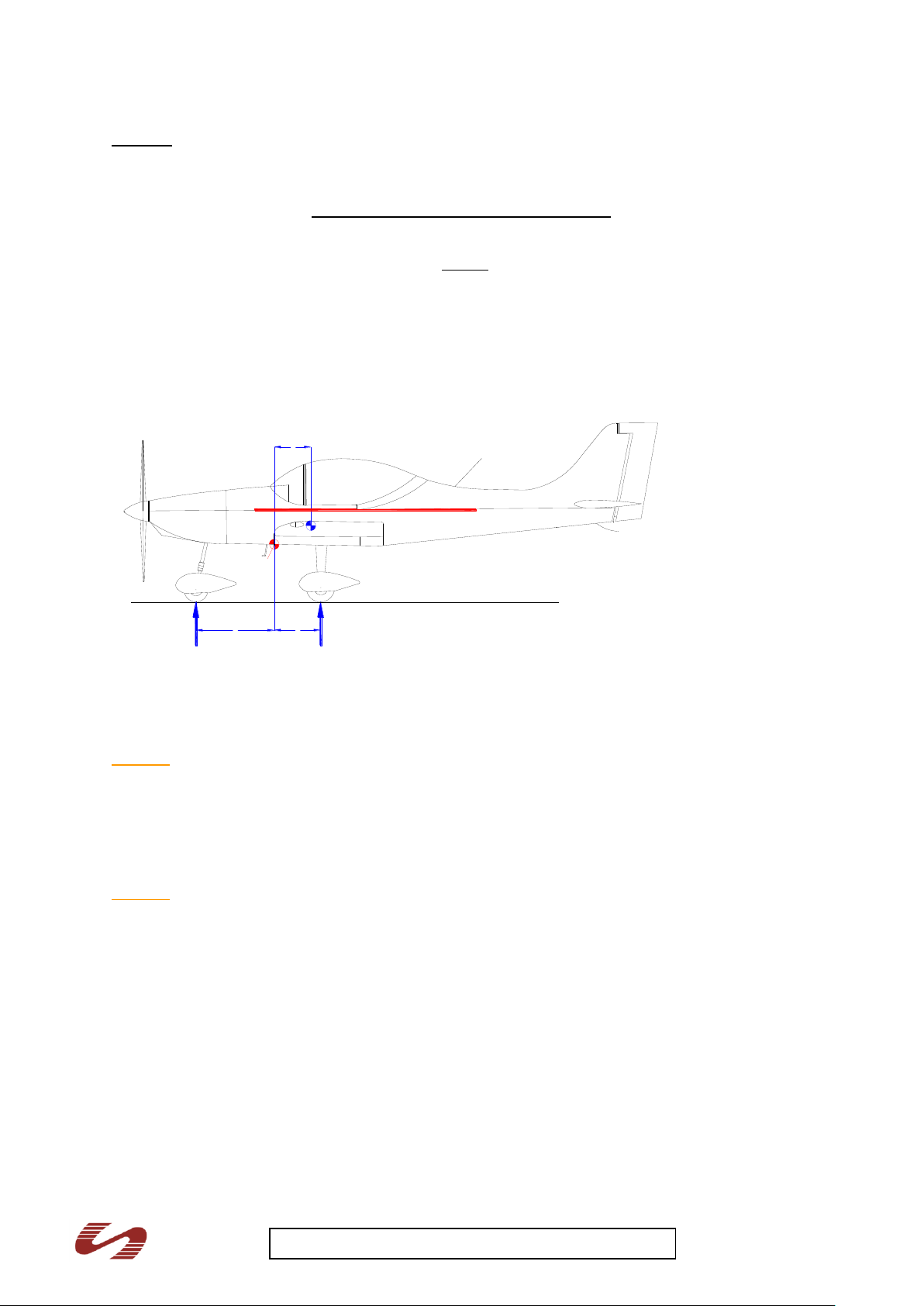
Scales are placed under each wheel of the aircraft. 'The aeroplane must be weighed level using the
canopy frame of the canopy guiding rail as a reference.'
The distances A and B from the BP are identical for each aircraft as they are accurately factory
produced. They are
A = 570mm
B = -1100mm
Subsequently, the weights W1 and W2 (WLeft + WRight) can be measured and added to the equation
below providing the aircraft CG at empty weight.
Formula:
D = W2 (main wheel weight) x 570 mm + W1 (nose wheel weight) x -1100 mm
W1 + W2
24
Page 25
Breezer M400 UK-22 Pilot Operating Handbook iss 1
D
A
B
W1 W2
BE
BP
Example
W2 (left) = 121.3kg
W2 (right) = 122.05kg
W1 Nose = 54.25kg
( (121.3 + 122.05) X 570) + (54.25 X -1100)
121.3 + 122.05 + 54.25
D (empty weight CG point) = 79,034 = 265.6mm
297.6
Weighing diagram – Breezer
The most important arms, measured from the BP (wing leading edge), are:
Pilots 687 mm (27.0”)
Baggage 1620 mm (63.8”)
Fuel -215 mm ( -8.5”)
Caution
The fuel moment is always negative, because the fuel tank lies in front of the reference datum.
The operating centre of gravity range is:
Forward: 258 mm / 19% MAC
Rearward: 448 mm / 33% MAC
Caution
The following diagrams are only examples - the empty weight centre of gravity of your Breezer can
deviate from this example. Use the data of the weighing diagram for the calculations!
25
Page 26

Breezer M400 UK-22 Pilot Operating Handbook iss 1
Calculation of the
loading condition
Example Calculation
Mass
[kg]
Moment
[kgmm]
1. Empty weight
297,2
79034
2. Pilot and Co-pilot, H: 687 mm
128,0
87.936,0
3. Baggage, H: 1620 mm
2,0
3.240,0
Mass and momentum with empty
tank (1.-3.)
427,2
170,210
CG, empty tank =
𝒎𝒐𝒎𝒆𝒏𝒕𝒖𝒎
𝒎𝒂𝒔𝒔
360 mm
4. Fuel, H: - 215 mm
45,3
- 9.739,5
Mass and momentum @ MTOW
472,5
160470
CG @ MTOW =
𝒎𝒐𝒎𝒆𝒏𝒕𝒖𝒎
𝒎𝒂𝒔𝒔
340 mm
Allowed CG range: 258 mm – 448 mm
Caution
Baggage of up to 15kg (structural limit) may be loaded into the aircraft rear parcel shelf, but in line
with the pilots on board and the MAUW restrictions.
Note
The pilot is responsible for ensuring that the MTOW is not exceeded.
26
Page 27

Breezer M400 UK-22 Pilot Operating Handbook iss 1
VI.3 Weighing report example
A current BMAA weight and balance report is supplied with each Aircraft from Breezer Aviation
VII Aircraft and systems description
VII.1 Structure
Fuselage
The construction of the load-bearing structure of the fuselage is a conventional aluminum stressed-
skin design. L-shaped profiles are used as stringers as reinforcement. The spars and ribs of the
vertical tail form part of the fuselage structure; the skin of the completely symmetrical vertical tail is
formed by the glass-fibre panel. The fuselage ends at the engine compartment side at the firewall.
The engine is attached to the firewall via engine mounts made of welded steel tubing. A two-piece,
glass-fibre cowling covers the engine compartment.
The Breezer fuselage has been designed and preliminarily accepted as meeting a calculated “infinite
fatigue life”. However, at 5000 hours discussions must take place with the BMAA as to any additional
inspections, checks or part replacement. The Breezer M400 operated outside the UK have examples
well in excess of 8000 hours and 18,000 landings.
Cockpit
The cockpit has two side-by-side seats. To facilitate boarding, part of the two-piece plexiglas canopy
can be pushed back.
Wings
The rectangular wing is of a conventional design and comprises:
• main spar
• auxiliary spar
• ribs
• skin
The fittings for the flaps and the ailerons are mounted on the auxiliary spar. For strength and weight
reasons, the skin varies in thickness. Glass-fibre wing tips are attached to the wing ends.
Empennage
As in the case of the wings, the completely symmetrical horizontal tail comprises a main spar, an
auxiliary spar, ribs, skin and glass-fibre surface tips.
Control surfaces, flaps
All control surfaces and flaps are of the same design and comprise a main spar, ribs and skin.
VII.2 Flight controls
Primary flight controls are operated by a control column and rudder pedals that operate in the
conventional sense. The elevator and ailerons are operated by push rods whereas the rudder is
operated conventionally via control cables. The nose wheel is also operated via push rods which are
attached to the rudder pedals. Elevator forces can be balanced by means of a trim tab on the
elevator. The flaps are extended mechanically.
Trims
The elevator and aileron trim tab is operated by a servo located in the elevator and aileron
respectively. The relevant switch is marked on the instrument panel. By pressing the rocker-type
switch, a pitch or roll trim change can be achieved as placarded:
Flaps
The flap lever is located in the middle console between the seats. It is operated in the same way as a
car hand brake lever. The flaps can be extended to three marked positions: 15°, 25° and 45°. The
locking-in of the flap lever can be heard as well as felt. Should an inexperienced pilot not be able to
determine to what position he has extended the flaps, he can check the position by looking out of the
cockpit window and looking at the flaps.
27
Page 28
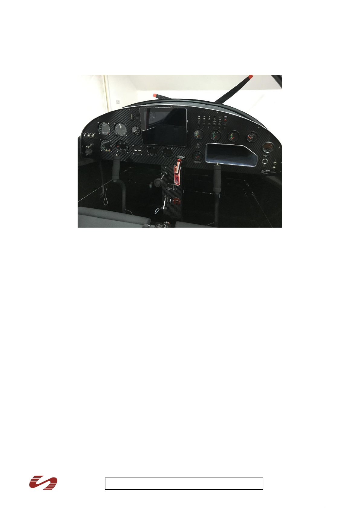
Breezer M400 UK-22 Pilot Operating Handbook iss 1
VII.3 Instrument panel example
VII.4 Landing gear
The main landing gear of the Breezer comprises two glass-fibre struts which are attached to the
underside of the fuselage. The wheel axles are screwed to the lower part of the strut. The main wheel
tyres are 4.00 x 6 (tyre pressure: 2.2 bar).
Shock absorption of the nose wheel landing gear which is made of high-strength steel tubes is
provided by three rubber buffers and a steel spring. The nose wheel tyre is 4.00 x 4 (tyre pressure:
1.8 bar). The nose wheel landing gear is steered via push rods which are attached to the rudder
pedals.
Wheel fairings are optional. They reduce drag and keep the aeroplane remarkably clean.
VII.4.1 Brake system
The main landing gear wheels are provided with hydraulic disc-type brakes actuated by a hand lever,
which is installed between the seats.
For parking, a locking lever must be actuated which is positioned at the hand lever.
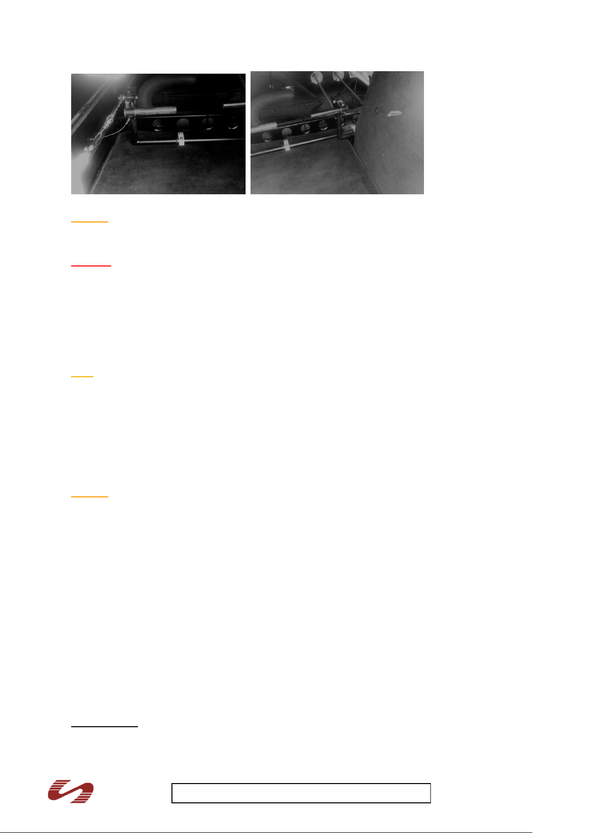
VII.4.2 Adjustable rudder pedals
3.6 Adjustable rudder pedals for the pilot can be ordered as an option.
Each pedal is actuated by a thin steel wire, fixed at the side of the fuselage and the central console
underneath the instrument panel, which has to be pulled for actuating the mechanism.
The pedals can be moved into two positions, full back or forward. While pulling the steel wire, the
pedal can be adjusted by pushing/pulling it with the feet rotating it into the position which is
comfortable for the pilot. Below: Left and rudder pedal with steel wire adjuster
28
Page 29
Breezer M400 UK-22 Pilot Operating Handbook iss 1
Caution
Before using the adjustable pedals, try to adjust them for min. 5 – 10 times to be familiar with the
system. If the pedals are locked correctly, you will hear a loud and clear “click”
Warning
- Be sure that the pedals are always locked correctly before take-off – otherwise they may
displace during the flight! It is forbidden to adjust the pedals during the flight!
VII.5 Seats and safety harnesses
The seat buckets are made of aluminium and are riveted to the fuselage. Hand-holes have been
integrated into the airframe near the seats to facilitate maintenance work and dismantling the wing.
The seat cushioning can be removed. Each seat has a four-point safety harness which is attached to
the fuselage structure at re-enforced attachment points. The harness has a central lap buckle.
Note
The safety harness should be adjusted to ensure that the lap belt is actually in the lap area and the
shoulder harness only permits slight forward movement. Only in this way can you be sure that the
harness will operate properly in turbulent weather or in an emergency.
VII.6 Baggage compartment
The baggage compartment is located behind the seats. Baggage should be evenly distributed in the
compartment and tied down appropriately to prevent it from moving in flight (or coming loose and
injuring the crew in an accident).
Caution
- Do not load more than 15 kg into the baggage compartment. Load evenly in the area whenever
possible.
VII.7 Canopy
The two-piece canopy is designed as a sliding canopy. The non-movable front part of the canopy is
fixed to the front fuselage fairing and is reinforced by a glass-fibre frame. The rear, sliding part of the
canopy is adhered to a glass-fibre frame and runs in two rails. The cockpit canopy lock is opened by a
quarter turn to the left, once the locking mechanism has hooked in, it can be locked by a quarter turn
to the right.
An optional canopy lock is available for use taxiing and in flight up to 70 Mph
VII.8 Engine
The Rotax 912ULS is a liquid/air-cooled, four cylinder, four-stroke, opposed cylinder engine which
drives the propeller via a gear box.
Rotax 912ULS
Engine displacement: 1352 cm³
Gear box: reduction 2.43 : 1
29
Page 30

Breezer M400 UK-22 Pilot Operating Handbook iss 1
Maximum take-off power: 73.5 kW (100 hp) @ 5800 rpm (max.5 mins)
Maximum continuous power: 69 kW (95 HP) @ 5500 rpm
Fuel grade: unleaded super / AVGAS 100LL
Interval between oil changes: 25 hr, 50 hr, 100 hr and then every following 100 hr
Interval between spark plug changes: every 200 h
The above is a reference, the latest Rotax engine manual recommendations superceed the above.
Refer to the latest engine manual for all information concerning maintenance, service intervals and
inspections.
The cowling must be removed for engine inspection. The locks can be easily removed by pressing
gently and simultaneously making a quarter turn to the left.
The upper half of the cowling should be removed before the first flight of the day in order to carry out
the pre-flight inspection described in Chapter IV. To check the oil level, the oil tank cap and the oil dip
stick must be removed. The oil should reach the uppermost mark on the dip stick.
Coolant level can be checked at the coolant reservoir / compensator at the firewall. The container
should be half-full.
All of the tested propellers on the Breezer are optimized by Breezer Aviation to ensure an optimum
combination of climb and cruise performance.
Note
Always use a screw-driver of the right size to release the screws and guide it with your other
hand. This prevents the screwdriver from slipping and scratching the paintwork.
Bear in mind that the engines used in the Breezer are not certified. Prepare your flight so that
you can always reach an emergency landing area should you experience engine failure.
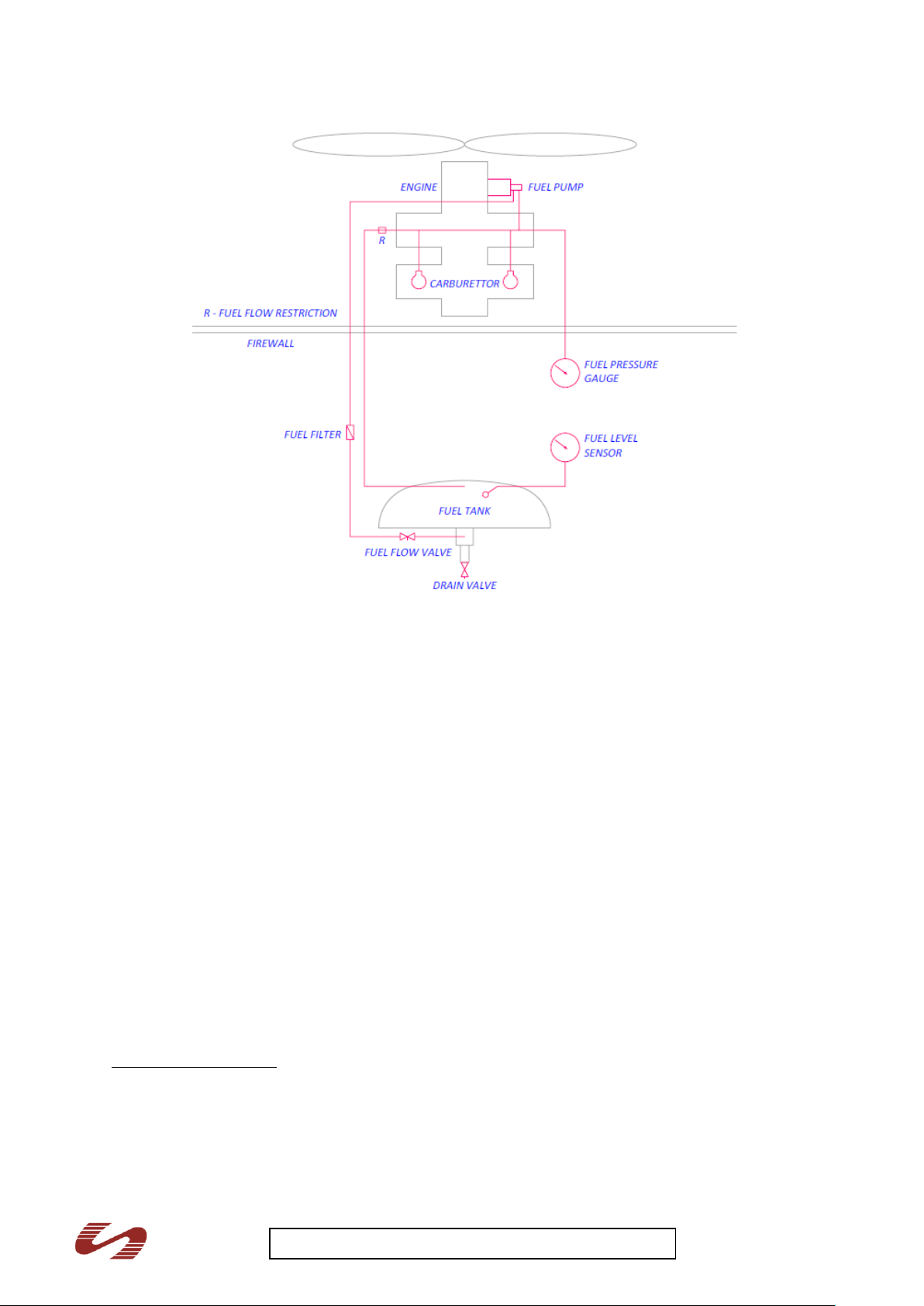
VII.9 Fuel system
The aluminium tank is located between the firewall and the instrument panel. It holds 76 litres, 74
litres are usable. The filler neck is screwed into the fuselage covering. The drain valve is on the
underside of the fuselage just behind the firewall. The spring-loaded valve is opened by pressing the
drain cup into it.
Schematic diagram – Fuel system
30
Page 31
Breezer M400 UK-22 Pilot Operating Handbook iss 1
VII.10 Electrical system
A simplified circuit plan for the standard configuration is to be found in the appendix (Chap. X.5).
Deviations from this standard configuration may occur if additional equipment is installed.
VII.11 Pilot-static system
A pick-up for pitot and static pressure is to be found on the underside of the right wing. Two thin tubes
attach the instruments in the cockpit to this device.
VII.12 Avionics
Radio and navigation instruments are not mandatory parts of the minimum equipment required to
operate in microlight aircraft. It is, however, in the interest of safety to install a radio, an intercom and
a GPS. Every additional piece of equipment will, however, increase the empty weight of the
aeroplane.
VII.13 Placards
The locations and types of the placards are given below:
Fuel grade and amount:
Near the fuel tank filler cap on the front fuselage cover. By the fuel gauge
31
Page 32

Breezer M400 UK-22 Pilot Operating Handbook iss 1
Operating Limitations Mph
VNE 150 mph
VFE 78 mph
VA 86 mph
VNO 119 mph
RPM max. (5 mins) 5800 rpm
RPM max. continuous 5500 rpm
Efficiency max rpm 4400 rpm
Oil pressure 2 - 5 bar (29 – 72 psi)
Oil Temp. Min. 50C
Oil Temp. Max. 130C
Coolant Max. 120C
Fuel Specification:
Mogas En228 Min Ron 90 or
Avgas 100LL
Usable fuel Capacity 74 Ltrs
Operating Limitations Kts
VNE 130 kts
VFE 68 kts
VA 75 kts
VNO 103 kts
RPM max. (5 mins) 5800 rpm
RPM max. continuous 5500 rpm
Efficiency max rpm 4400 rpm
Oil pressure 2 - 5 bar (29 – 72 psi)
Oil Temp. Min. 50C
Oil Temp. Max. 130C
Coolant Max. 120C
Passenger Warning: This aircraft has not
been certified to an international requirement
Oil Capacity 3.4 litres
Use Rotax recommended oils
AEROBATICS and INTENTIONAL
SPINS ARE PROHIBITED
Warning placard - flight manoeuvres: On the instrument panel
Rotax 912ULS (100hp):
The following placard should be located on the instrument panel or in sight of the crew
Inside of the oil filling cowling flap
Checklist:
Position: within Pilot’s view
32
Page 33

Breezer M400 UK-22 Pilot Operating Handbook iss 1
Checklist
1. Canopy locked
2. Rescue system unlocked
3. Safety harness adjusted and locked
4. Fuel valve open
5. Amount of fuel sufficient for the flight
6. Altimeter adjusted
7. Flight controls free
8. Engine run up o.k
Max Baggage Load –
EMPTY WEIGHT: Kg
MAX PERMITTED GROSS T/O WEIGHT: 472.5 Kg
MAX SEAT LOAD: 105 Kg
MIN SEAT LOAD: 55 Kg
WARNING – Emergency Parachute
Switch off engine the pull handle to
deploy.
Unapproved equipment – see POH
Baggage loads:
On the shelf behind the seats – evenly distributed whenever possible, closest to seats when not.
15kg is maximum possible (structural) baggage limit at 1620mm, but each individual aircraft may have
a lower placarded limit for balance purposes. Each aircraft will be placarded with an individual
baggage limit.
A fuel trade off placard is supplied with each aircraft that provides fuel loads with different crew
weights
Miscellaneous markings – placards to indicate
Brake next to the brake handle with direction of operation
Choke next to the choke
Cabin heat next to the heater knob
Trim next to the trim switches
Flaps next to the flaps control lever
Main fuel shut off valve next to the fuel valve
Throttle next to throttle – push for power
Parachute placards
By the release handle
By the rocket exit area and either side of fuselage
33
Page 34

Breezer M400 UK-22 Pilot Operating Handbook iss 1
VIII Handling, service and maintenance
VIII.1 Introduction
This chapter contains procedures recommended by the Breezer Aviation for the proper ground
handling and routine care and servicing of the aircraft The aircraft must undergo an annual inspection
to be carried out by a BMAA inspector. All other inspections may be carried out by appropriately
qualified persons, with secondary inspections recommended as per BMAA.
Following the service intervals is in the interest of your own safety and will maintain the value of your
Breezer.
VIII.2 Maintenance intervals
Refer to the provided Breezer Maintenance Manual for a detailed description of the maintenance
intervals and the according tasks which need to be performed.
VIII.2.1 Changes / Repairs
Changes may only be carried out with the approval of Breezer Aviation or the BMAA. The
owner/operator may carry out repair work but this work is limited to the replacement of defect parts
with original parts. Repair work on the skin of the aircraft may be carried out with the approval of
Breezer Aviation or the BMAA.
VIII.3 Ground handling
The aircraft may only be moved by hand by pulling it at the propeller hub or optional tow bar located
on the front wheel main axle. It should not be pushed at the wing tips or at the control surfaces.
To move the aircraft backwards and during leveling, push down the fuselage at fuselage-vertical tail
connection and/or at the horizontal tail root (at the main spar) and position as required.
Use underwing tie down eyes for securing the aircraft whilst unattended.
VIII.4 Cleaning and care
A dirty Breezer does not perform as well as a clean one and dirt can cover damage. The aircraft
should, therefore, be cleaned at the end of each day of flight. Insects and light dirt are best removed
using suitable cleaning products recommended by Breezer Aviation or other reputable sources.
Depending upon type of operation and weather conditions the painted surfaces should be polished
and waxed at least once a year.
Owners should avoid parking the aircraft for long periods in the bright sunlight or in rain; if necessary,
use a dedicated aircraft cover to protect the Breezer from the weather.
VIII.5 Special operating conditions
If the aircraft is operated with wheel fairings from muddy runways, make sure that no mud
collects in the rear part of the fairing.
During winter operations, this mud or snow could freeze in the air and the wheels could block.
During winter operations, carefully remove all snow from the wings and make sure that the
control surfaces move freely.
If during winter operations the engine does not reach its minimum operating temperature of
90°C, partially cover the oil cooler with the optional Breezer oil rad cover.
IX Equipment
IX.1 Minimum equipment
The following items constitute the minimum equipment for the operation of a Breezer:
1 airspeed indicator, min. range 170 Mph
1 compass
1 altimeter, range 10,000 ft
1 recovery system for the appropriate speed range
2 four-point seat harnesses
1 data plate, 1 identification plate, 1 check list, easily visible
Engine instruments – oil temp and pressure, coolant temp. Optional additional instruments
such as volt metre and fuel pressure gauge also available.
BRS 6 1050 Parachute
.
34
Page 35

Breezer M400 UK-22 Pilot Operating Handbook iss 1
The pilot must be dressed to suit conditions and all mandatory documents must be on board the
aircraft (air map for example)
IX.2 Recovery system
The recovery system is installed between the firewall and the fuel tank under the front turtle deck. The
fuselage has a special covering here so as not to impede the rocket when fired. The exit area is
marked by a placard. The front turtle deck can be removed for maintenance purposes by removing
the lateral screws and those in the firewall.
The release lever is located in the middle console. A hand force of up to 12 kg is required to operate
the lever - if necessary, pull with both hands!
Technical data
max. operating speed 150 Mph
max. supported mass 475kg
mass with attachment straps approx. 12 kg
Refer to the recovery system operating manual for further information on function and technical
details.
Note
The parachute and the rocket must be inspected and serviced regularly. A record of parachute
system maintenance must be entered in the airframe logbook. Refer to the operating manual from the
parachute manufacturers for detailed information.
Warning
Secure the recovery system against unintentional deployment on the ground
Remove the safety pin before each flight - it could be too late during flight
Before deploying the recovery system, shut down the engine - in an uncontrollable situation,
the propeller could sever an attachment strap when the parachute opens.
Occupant Warning – The parachute recovery system installation has been approved by
BMAA on the basis that, as far as is practicable to demonstrate, it will create no hazard to the
aeroplane, its occupant(s) or ground personnel whilst the system is not deployed; and that
when properly maintained, the risk of malfunction, deterioration or inadvertent deployment is
minimised.
The BMAA has not approved the system itself or considered the circumstances, if any, in
which it might be deployed. The effectiveness of the system for the safe recovery of the
aeroplane has not been demonstrated.
IX.3 Optional equipment
On request, optional equipment such as transponder, radio, artificial horizon, GPS, Glass screens
may be installed in the aircraft.
Caution
Every additional piece of equipment increases the empty mass and thus reduces the useful load of
the aircraft.
35
Page 36

Breezer M400 UK-22 Pilot Operating Handbook iss 1
X Appendix
X.1 Check list
Before starting the engine
1. Pre-flight inspection complete
2. Seat belts adjust and lock
3. Canopy locked, lever to the left
4. Amount of fuel sufficient for the planned flight
5. Controls check freedom of movement
6. Fuel valve open
7. Throttle check freedom of movement, friction lock
Starting the engine (Brake on)
1. Propeller area clear
2. Choke pull on for first start or cold start
3. Master switch ON
4. Ignition – both circuits ON
5. Starter turn, pick up engine on throttle
6. Oil pressure check
Taxiing (release Brake)
1. Electrical equipment ON
2. Flight instruments and avionics ON and set
3. Brakes check
4. Directional control check full and free
5. Flight instruments and avionics check (if possible)
6. Mag check at 4000 rpm
Take off
1. Trim neutral
2. Flap stage one
2. Throttle full open
3. Elevator neutral
4. Hold direction using the rudders
5. Take-off airspeed 50 Mph
6. Increase airspeed and climb out with 70 Mph
7. Flap retract at 70 mph
Cruise
1. Climb to cruising altitude
2. Rpm / airspeed as required
Descent
1. Reduce airspeed to 80 Mph
2. Throttle as required
Approach (see detailed technique in para IV.3 page 21)
1. Final approach airspeed 60 Mph
2. Flaps set as required
3. Touchdown main landing gear first
4. Brake as required
Shutting down and securing the aeroplane
1. Throttle idle
2. Avionics OFF
36
Page 37
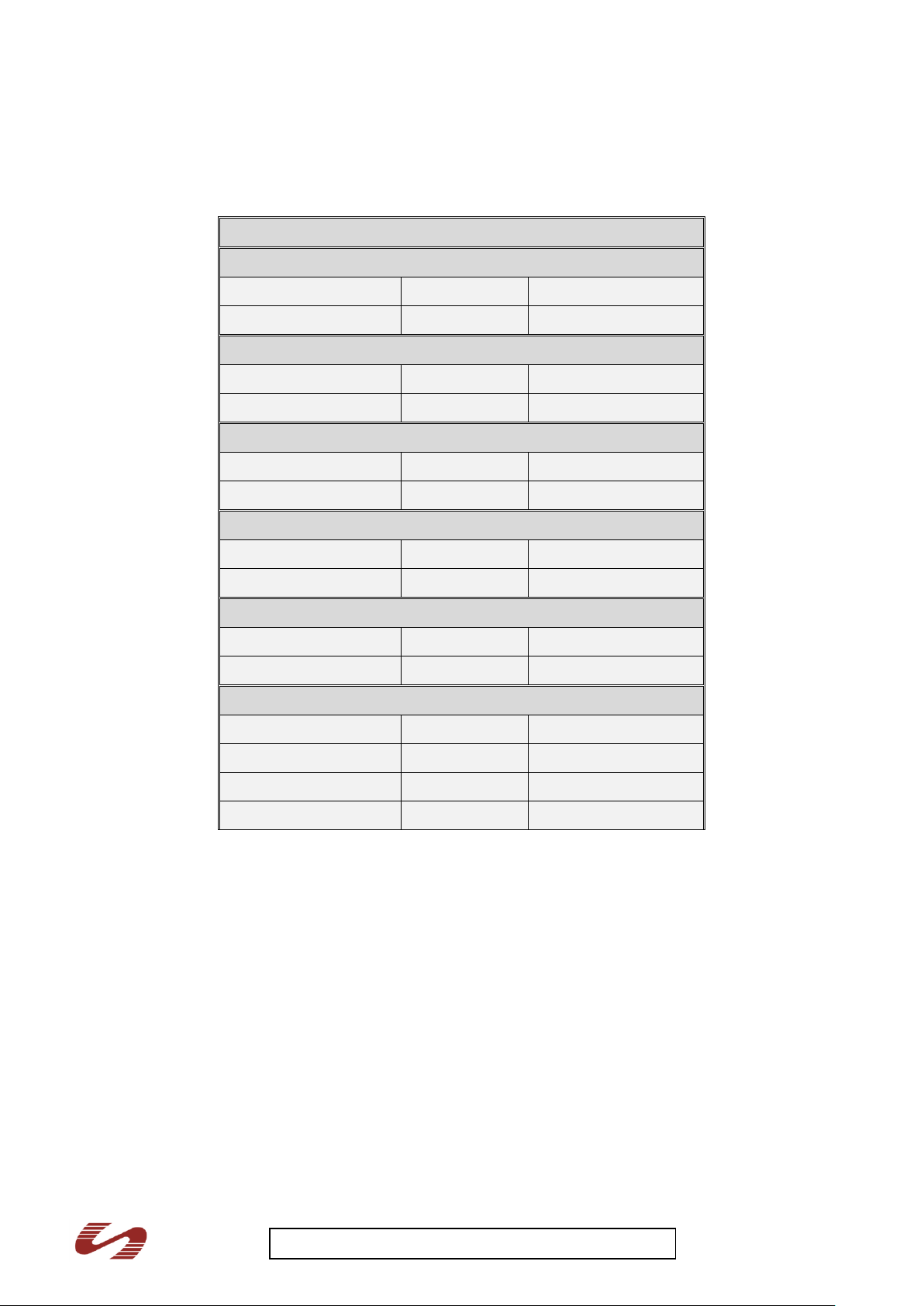
Breezer M400 UK-22 Pilot Operating Handbook iss 1
3. Ignition – both circuits OFF
Deflection
Aileron
Deflection - upwards
19
O
± 1.5
O
109 mm ± 9 mm
Deflection - downwards
14
O
± 1.5
O
79 mm ± 7.5mm
Trim tab - aileron
Deflection - upwards
50 O ± 2 O
Deflection - downwards
42 O ± 2 O
Elevator
Deflection - upwards
25 O ± 1
O
136 mm ± 5 mm
Deflection - downwards
20 O ± 1 O
110 ± 5 mm
Trim tab - elevator
Deflection - upwards
21 O ± 2 O
Deflection - downwards
34 O ± 2 O
Rudder
Deflection - left
25 O ± 1 O
198 mm ± 8 mm
Deflection - right
25 O ± 1 O
198 mm ± 8 mm
Wing flap
Retracted
0 O
0 mm
1. Step
15 O ± 1 O
65 mm ± 4 mm
2. Step
25O ± 1 O
109 mm ± 4 mm
3. Step
45 O ± +0/-2 O
186 mm +0/-8 mm
4. Master switch OFF
5. Recovery system secure
X.2 Control surface deflections and weights
37
Page 38
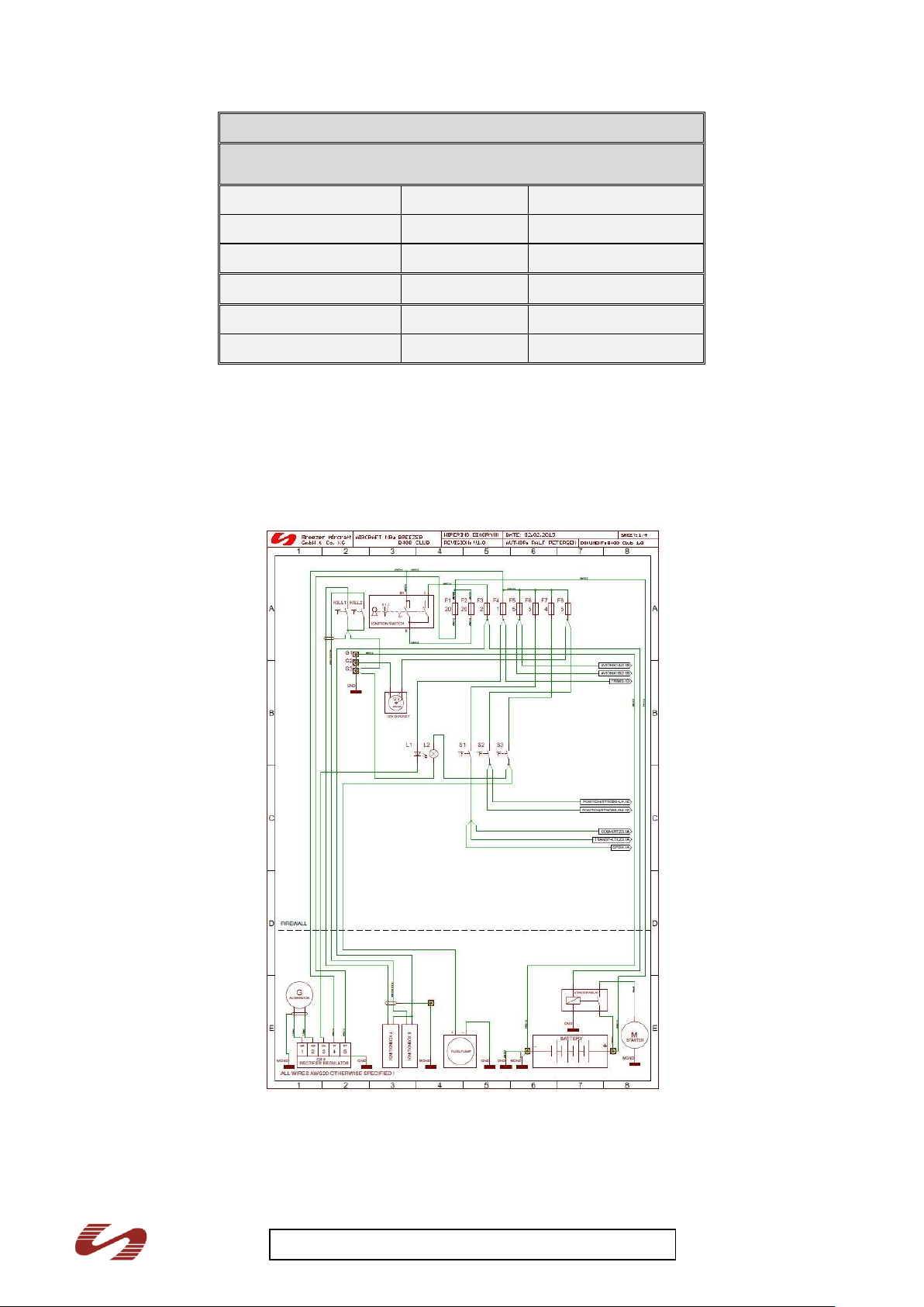
Breezer M400 UK-22 Pilot Operating Handbook iss 1
Weight and balance
Gross weight
[kg]
Trailing edge weight
[kg]
Elevator - starboard
2.34 - 2.92
-0.15 - 0.39
Elevator - port
2.56 - 3.12
0.00 - 0.56
Rudder
1.98 - 2.42
0.43 - 0.87
Flap (each)
2.48 - 3.04
0.38 - 0.94
Aileron - starboard
2.99 - 3.65
0.32 - 0.98
Aileron - port
2.84 - 3.47
0.18 - 0.89
Note: The Gross Weight is the allowable weight range of the control surface off the aircraft. The Trailing
Edge Weight is the allowable force range required to support the trailing edge with the control surface
horizontal and otherwise supported only by its hinge. The data above are for control surfaces with mass
balances attached (the flaps and rudder are not mass balanced).
X.3 Electrical circuit plan example.
Each Breezer will be delivered with its own circuit diagram to cater for any minor differences
38
Page 39
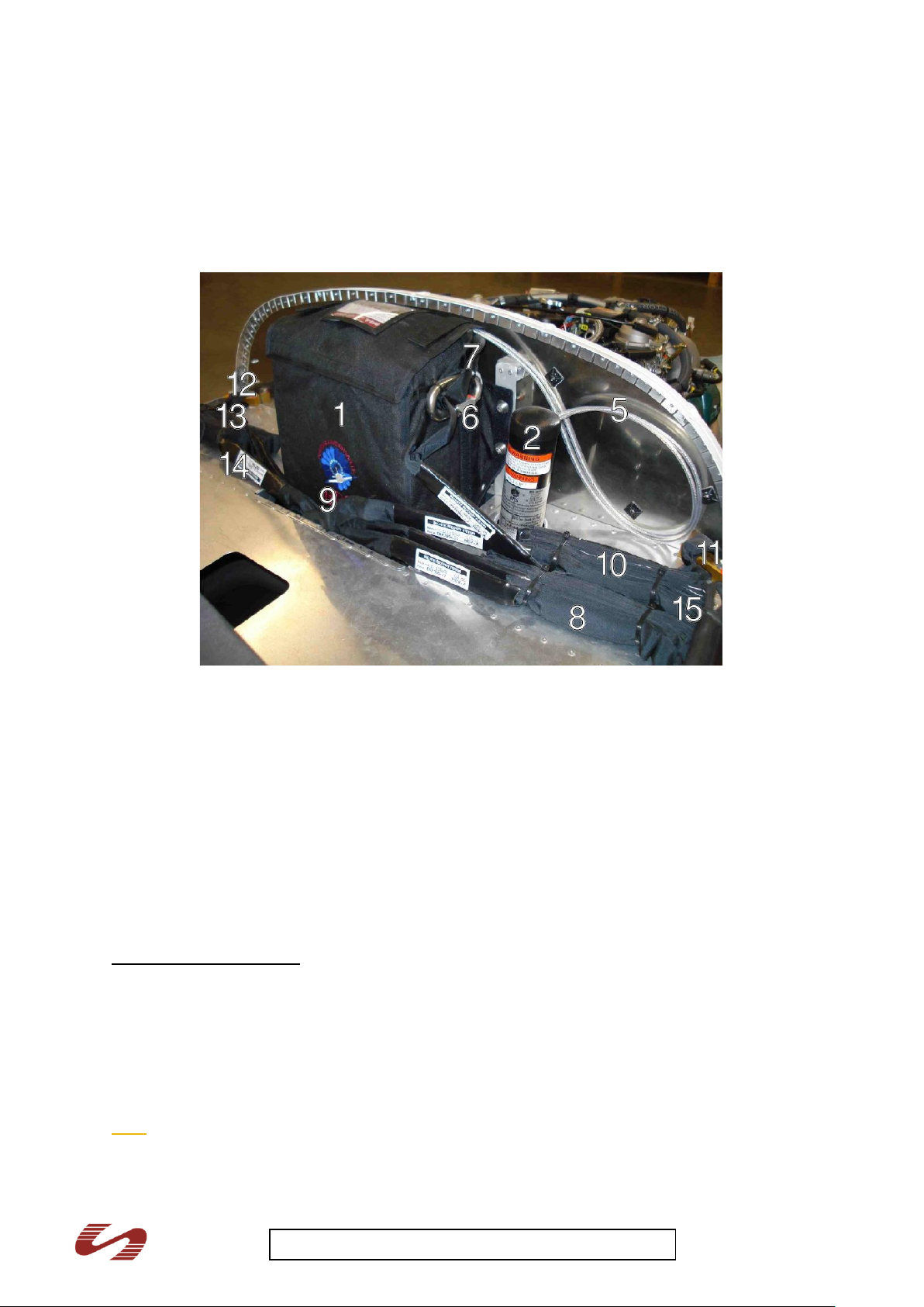
Breezer M400 UK-22 Pilot Operating Handbook iss 1
X.4 Recovery system installation
1.
Textile container - recovery
parachute
10.
Rolled up strap - from right
2.
Rocket, firing direction, oblique
to the right
11.
Rolled up strap - from left
3.
Bowden cable
12.
Strap - rear left
4.
Release lever in middle console
13.
Strap - rear right
5.
Pull line
14.
Shackle - parachute / strap
6.
Shackle
15.
Parachute base line
7.
Line to parachute cap
16.
Glass-fibre covering - rear
right strap
8.
Left attachment point - front
17.
Attachment point - rear right
9.
Right attachment point - front
The recovery system is installed by Breezer Aviation. Should it be necessary to remove and re-install
the system for service reasons, please contact Breezer Aviation for instructions and obtain a
secondary inspection.
Recovery system–view of fuselage from the right
Identical items to points 16. and 17. are to be found on the left side
Recovery system operation
By pulling the release lever (4), the Bowden cable (3) will release the rocket (2). The rocket is
attached to the line to the parachute cap (7) via the pull line (5) and a shackle (6). The former line
goes into the textile recovery chute bag. The shackle (14) is the link connecting the parachute base
line (15) and the attachment straps (10, 11, 12, 13, 14). The front straps are attached to the upper
engine mount attachment points (8, 9). The straps are rolled up and attached to the firewall by means
of clamping bands. The rear straps are routed along the outer side of the fuselage to the attachment
points (17). They have a protective glass-fibre covering. The front straps are 4200 mm long whereas
the rear straps measure 3600 mm.
Note
The straps must be laid so that they do not interfere with each other and cannot loop when
the parachute is released.
39
Page 40

Breezer M400 UK-22 Pilot Operating Handbook iss 1
The parachute and the rocket must be inspected and serviced regularly. Refer to the recovery
system operating manual for further details.
A record of parachute system maintenance must be entered in the airframe logbook.
Warning
When dealing with the recovery system, the owner/operator should remember that he/she is dealing
with a pyrotechnical system. Improper handling can lead to dangerous situations arising which, in
turn, could lead to severe bodily injury. Refer to the recovery system operating manual for further
details concerning operating and for relevant technical data.
40
 Loading...