

BreezeCOM BreezeACCESS II SU-R Series, BreezeACCESS II SU-R-8D1V, BreezeACCESS II SU-R-8D, BreezeACCESS II SU-R-BD Installation Manual
Page 1

BreezeACCESS I I
I ndoor Subscriber Units
SU-R Seri es
FCCID: LKT-SUR-24
Installation
Manual
April, 2001
Cat. No. 213
Page 2

Front Matter
© 2001 by BreezeCOM Ltd. All rights reserved.
No part of this publication may be reproduced in any material form without the written permission of the
copyright owner.
Trad e Names
BreezeACCESS, BreezeNET, BreezeLINK, BreezeMANAGE, BreezeVIEW and BreezeWIZARD are
trade names of BreezeCOM Ltd. Other brand and product names are registered trademarks or
trademarks of their respective companies.
Statement of Conditions
The information contained in this manual is subject to change without notice. BreezeCOM shall not be
liable for errors contained herein or for incidental or consequential damages in connection with the
furnishing, performance, or use of this manual or equipment supplied with it.
Warranty
In the following warranty text, “the Company” shall mean:
•
BreezeCOM Ltd., for products located outside the USA.
•
BreezeCOM Inc., for products located in the USA.
This BreezeACCESS product is warranted against defects in material and workmanship for a period of
one year from date of purchase. During this warranty period the Company will, at its option, either
repair or replace products that prove to be defective.
For warranty service or repair, the product must be returned to a service facility designated by the
Company. Authorization to return products must be obtained prior to shipment. The buyer shall pay all
shipping charges to the Company and the Company shall pay shipping charges to return the product to the
buyer within the USA.
The Company warrants that the firmware designed by it for use with the unit will execute its
programming instructions when properly installed on the unit. The Company does not warrant that the
operation of the unit or firmware will be uninterrupted or error-free.
Limitation of Warranty
The foregoing warranty shall not apply to defects resulting from improper or inadequate maintenance by
the buyer, buyer supplied interfacing, unauthorized modification or misuse, operation outside of the
environmental specifications for the product, or improper site preparation or maintenance. No other
warranty is expressed or implied. The company specifically disclaims the implied warranties of
merchantability and fitness for any particular purpose.
BreezeACCESS II Series ii SU-R Installation Manual
Page 3

Front Matter
BreezeCOM shall not be liable to any person for any special or indirect damages, including, but not
limited to, loss of profits or revenues, loss of use or damage to any associated equipment, cost of
capital, cost of substitute products, facilities or services, downtime costs or claims resulting from any
cause whatsoever arising from or in any way connected with the manufacture, sale, handling, service,
repair, maintenance or use of the products. In no event shall the company’s liability exceed the purchase
price denoted on the invoice.
Elect roni c E mission No t ice
This device complies with Part 15 of the FCC rules. Operation is subject to the following two
conditions:
1. This device may not cause harmful interference.
2. This device must accept any interference received, including interference that may cause undesired
operation.
FCC Rad io F requency In t erf erence Stat ement
This equipment has been tested and found to comply with the limits for a class B digital device, pursuant
to Part 15 of the FCC rules. These limits are designed to provide reasonable protection against harmful
interference when the equipment is operated in a residential environment notwithstanding use in
commercial, business and industrial environments. This equipment generates, uses, and can radiate radio
frequency energy and, if not installed and used in accordance with the instruction manual, may cause
harmful interference to radio communications.
FCC Rad iation Hazard Warnin g
To comply with FCC RF exposure requirements in section 1.1307, a minimum separation distance 20cm
(8 inches) is required between the antenna and all persons.
Information to User
Any changes or modifications of equipment not expressly approved by the manufacturer could void the
user’s authority to operate the equipment.
Safety Considerations
For the following safety considerations, “Instrument” means the BreezeACCESS Subscriber Unit
components .
Caution
To avoid shock, do not perform any servicing unless you are qualified to do so.
SU-R Installation Manual iii BreezeACCESS II Series
Page 4

Front Matter
Line Voltage
Before connecting this instrument to the power line, make sure that the voltage of the power source
matches the requirements of the instrument.
Radio
The instrument transmits radio energy during normal operation. To avoid possible harmful exposure to
this energy, do not stand or work for extended periods of time in front of its antenna. The long-term
characteristics or the possible physiological effects of Radio Frequency Electromagnetic fields have not
been yet fully investigated.
BreezeACCESS II Series iv SU-R Installation Manual
Page 5

Table of Contents
Table of Contents
1. Introduction _______________________________________________________ 1
2. Basic Installation ___________________________________________________ 2
2.1 Packing List ___________________________________________________ 2
2.2 Other Required Items___________________________________________ 2
2.3 Installation Overview ___________________________________________ 3
2.4 Installation Guidelines __________________________________________ 3
2.5 Wall Mounting the Unit _________________________________________ 5
2.6 Connecting the Antenna (A7 model) _______________________________ 5
2.7 Connecting the Unit to the Power Supply and to the CPE _____________ 5
3. Configuring System Parameters _______________________________________ 7
3.1 Getting Started with the Local Terminal ___________________________ 7
3.2 Configuring Basic Parameters____________________________________ 9
3.3 Reset Unit____________________________________________________ 11
4. Aligning the Antenna (A7 model) _____________________________________ 12
4.1 Aligning the Antenna Using the LEDs_____________________________ 12
4.2 Aligning the Antenna Using the Site Survey Menu __________________ 12
5. Maximum Data Rate Configuration ___________________________________ 14
6. Verifying Proper Operation__________________________________________ 15
6.1 Checking the LEDs ____________________________________________ 15
6.2 Verifying the Ethernet Connection _______________________________ 15
6.3 Verifying Data Connectivity_____________________________________ 16
6.4 Verifying Telephone Connectivity (units with voice support)__________ 16
7. Specifications _____________________________________________________ 17
BreezeACCESS II Series v SU-R Installation Manual
Page 6

Table of Contents
7.1 Radio________________________________________________________ 17
7.2 Data Communication___________________________________________ 17
7.3 Voice Communication (units with voice support)____________________ 17
7.4 Configuration and Management _________________________________ 18
7.5 Interfaces ____________________________________________________ 18
7.6 Electrical ____________________________________________________ 18
7.7 Mechanical___________________________________________________ 18
7.8 Environmental________________________________________________ 19
7.9 Standards Compliance, General _________________________________ 19
Appendix A. Using Telnet
_____________________________________ 21
Appendix B: Basic Parameters
_______________________________ 23
BreezeACCESS II Series vi SU-R Installation Manual
Page 7

Introduction
1. INTRODUCTION
This manual describes installatio n guidelines for BreezeACC ESS II SU-R Sub s cribe r Units.
The BreezeACCESS Broadband Wireless Access system allows access service providers to
provide high-speed IP connectivity services to their subscribers. T o s upport IP-based s e rvices
effectively BreezeACCESS systems employ wireless packet data switching technology.
The BreezeACCESS II line of products uses Frequency Hopping Spread Spectrum radios that
operate in Time Division Duplex (TDD) mode in the license free 2.4 – 2. 5 G Hz frequency range.
The SU-R line of Subscriber Units comprises compact units that are designed for indoor
installation. SU-R units are available in several models differing from each other in the type of
supported data networks and availability of voice service s as follows:
• SU-R-8D units support up to 8 Ethernet workstations / PCs (8 MAC addresses).
• SU-R-BD units provide a full bridge functionality supporting up to 512 MA C addres s e s.
• SU-R-8D1V support up to 8 Ethernet works tations / PCs and have an interface to a standard
telephone set.
SU-R units are available e ither with two 3 dBi omni antennas (A models) or with an indoor
wall/window mountable 7 dBi UNI-7 or UN I-8.5 dBi antenna w/integral cab le (-A7 models).
Note:
SU-R Installation Manual 1 BreezeACCESS II Series
The i nf ormation contai ned in this manual is appl i cable to Br eezeACCESS SU -R-MMD S
units with softwar e release 3.0 and up.
Page 8

Basic Installation
2. BASIC INSTALLATION
2.1 Packing List
The SU-R units are shipped with the following units and accessories. The exact packing list
varies depending on system configuration and ordered equipment.
• SU-R unit:
⇒ SU-R-A with 2 omni antenna s
or
⇒ SU-R-A7 unit
• An SMA adap te r (with SU-R-A7 units)
• UNI-7 or UNI-8.5 antenna with 3 m cable and a mounting kit (with the SU-R-A7 units)
• A power supply
• Wall mounting kit for the SU-R unit (two anchors and screws)
• An Ethernet cable (straight)
2.2 Other Required Items
The following items must be av aila ble for the installation
• An Ethernet cable (crossed) if the unit should be connected to a hub (the s traight Ethernet
cable s up plie d with the unit is intended for connecting it directly to a PC or to a hub’s uplink
port)
• A PC with terminal emulation program
• A monitor cable* for co nfiguration and testing via the Monitor inte rface
• Ins ta llatio n tools and materials
Items marke d with an as t erisk (*) are available from BreezeCOM.
BreezeACCESS II Series 2 SU-R Installation Manual
Page 9

Basic Installation
2.3 Installation Overview
Standard installation involves the following steps:
1. Verify that all components of the pack ing list, described in Section 2.1, are intact and verify
availability of the required items liste d in Section 2.2.
2. Ins ta ll the unit and antenna in optimal locations as de s c ribed in Sections 2. 4 a nd 2.5 and in
the instructions su pplie d with the antenna.
Note:
To avoi d drilling unnec essary holes, it is recommended to verify good connectivity wit h t he
base station prior to drilling holes in the locations intended for the SU-R unit and/or the
detached antenna.
3. Connect the antenna to the unit as desc ribe d in Section 2.6.
4. Connect the power supply and the user’s equipment to the unit as desc ribed in Section 2.7.
5. Configure the basic sys te m parameters as described in Section 3.
6. Align the antenna for optimal connectivity (A7 models) and configu re the Maximum Data
Rate if applicable, as described in Chapters 4 and 5.
7. Check the functionality of the unit as describe d in Chapter 6.
2.4 Installation Guidelines
This sec tion desc ribe s the installation guidelines and the various co nsiderations that must be
taken into account when planning the installa tion.
2.4. 1 Location of the Uni t
• The unit can be placed on a desktop or a shelf, or can be attached to a wall.
• The unit should be installed as neat as possible to the antenna (-A7 models). The RF cable
connecting the unit to the antenna should be as short as possible to guarantee minimum power
loss.
SU-R Installation Manual 3 BreezeACCESS II Series
Page 10

Basic Installation
• Keep the units well away from sources of heat, such as radia tors , air-conditioners, etc.
2.4. 2 Location of the Antenna
• Any physical object in the path between two units can cause s ignal attenuation. Commo n
obstructions are buildings and trees. If a unit’s antenna is installed indoors , the walls and/or
windows between the two sites are physica l obs truc tions. If the antenna is positioned
outdoors, any buildings or other physical s tructure such as trees, mountains or other natural
geographic features higher than the antenna and situated in the path between the two sites can
constitute obs tructions.
• Insta ll indoor antenna s as c lose as pos s ible to a window (or wall if a window is not
accessible) facing the required direction. The UNI-7 or UNI-8.5 antenna may also be attached
to a fixed wind ow. Avoid metal obs tac le s s uc h as metal window frames or metal film antiglare windows in the trans mission path. Install outdoor antennas high enough to avoid any
obstacles , which ma y block the signal.
• Position the antennas c le ar of metal furniture and away from moving metal objects s uc h as
metal fans or doors.
2.4.3 Antenna Diversity
In a pplic atio ns where no multipath propagation is expected, a s ingle antenna is sufficient to ensure
good performance levels . However, in cas es where multipath propagation exists, BreezeCOM
recommends that two antennas be used. This takes advantage of space diversity capabilities. By
using two antennas per unit, the system can select the best antenna on a per-packet basis (every
seve ral milliseco nds).
Multipath propagation is to be e xpected when there are pote ntial reflectors be tween the Access
Unit and Subscriber Units. These reflectors may be buildings or moving objects such as airplanes
and motor vehicles. If this is the case, the radio signal does not travel in a straight line , but is
reflected or de flec ted off of the object, creating multiple propagation paths.
When installing a s ingle antenna , modify the transmit diversity option to either antenna 1 or
antenna 2, according to the antenna being used.
2.4.4 Antenna Polarization
Antenna pola rization must be the same at either end of the link. In mos t a pplic a tions, the preferred
orientation is ve rtical polarization. Above-ground propagation of the signal is better when it is
polarized vertically. For integral omni a ntennas (A model), make sure that the antennas are
BreezeACCESS II Series 4 SU-R Installation Manual
Page 11

Basic Installation
extended upward vertically in relation to the floor to achieve vertic al p olarization. For the
detached UNI-7 or UNI-8.5 antenna (A7 model) follow the instructions included with the a ntenna.
2.5 Wall Mounting the Unit
Note:
The template on the pac ka ging box can be used to mark the locations of the screws on the wall
(drill right through the markings on the box).
After insertion of the a nchors and screws, hang-on the unit on the two screws with the bottom
panel (the side with the connectors) facing downward.
In SU-R-A models with integral antennas, extend the a ntennas upward vertic ally in relation to the
floor to achieve vertica l pola rization.
To avoi d drilling unnecessary holes, it is recommended to ver ify connectivity with the base
station prior to drilling holes in the locations intended for the SU-R unit and/or the indoor
antenna.
2.6 Connecting the Antenna (A7 m odel)
Connect the special adapter to antenna port 1 (marked 1) on the side of the unit. Push the adapter
carefully into the hole us ing the alignment markings on the adapter and the unit, and turn it 180
degrees to firmly lock it.
2.7 Connecting the Uni t to the Power Supply and to the CPE
The unit operates on a power input of 5V DC, supplied by the power transformer include d with
the unit.
1. Plug the output jack of the power transformer into the DC input jack (ma rked DC IN)
located o n the bottom panel of the unit.
2. Connect the supplied universal power transformer to a powe r outlet - 110/ 220VAC.
3. Use a straight Ethernet 10BaseT cable to connect the Ethernet port (marked ETH) to a PC or
to a hub’s uplink port. Use a crossed cable to connect to a hub.
SU-R Installation Manual 5 BreezeACCESS II Series
Page 12

Basic Installation
4. For units with voic e s upport, use the standard cable connected to the telephone s et to
connect the telephone to the telephone port (marke d T EL).
BreezeACCESS II Series 6 SU-R Installation Manual
Page 13

Configuring System Parameters
3. CONFIGURING SYSTEM PARAMETERS
After completing the installation process, as described in the preceding sections of this manual,
proceed with configuration of the basic system parameters.
This manual covers the configuration of basic installation parameters. Refer to the Administration
Manual for informatio n rela t e d t o o ther p a ra mete rs.
Note:
Opti onal l y, the pr oduct can be configur ed using Telnet over the E t hernet por t , after setting
IP addr ess. F or furt her information, refer to A ppendix B.
3.1 Getting Started with the Local Terminal
1. Connect one end of the Monitor cable to the Monitor jack (marked MON) on the bottom
panel of the unit. Connect the second end of the cable to the COM port of the terminal. The
COM port connector on the Monitor cable is a 9 pin D-type plug.
2. Run a terminal emulation program (e.g., ProComm or Windows HyperTerminal) using the
following setup:
Baud rate
Data bits
Stop bits
Parity
Flow Control
Connector
3. Press
Enter
. The
your authorized access level. You will be requested to enter your password. After entering
the correct password, pres s enter. The main menu appears (refer to Figure 3-1).
9600
8
1
None
Xon/Xoff
Available C om Port
Select Access Level
menu appears. Select the access level according to
SU-R Installation Manual 7 BreezeACCESS II Series
Unit Type
Page 14

Configuring System Parameters
BreezeACCESS/SU-R
Official Release Version – 3.0.2
Release Date: Mon Oct 23 21:05:08 2000
Main Menu
=====================
1 – Info Screens
2 – Unit Control
3 – Basic Configuration
4 – Site Survey
5 – Advanced Configuration
>>>
Figure 3-1. Main Me nu
Software
Version No.
The appearance of the displayed
• For users with read only access rights, only the
this access level cannot access the
Advanced Configur ation
Main Me nu
me nus.
varies in accordance with the access level.
Info Screens
option is displaye d. Use rs with
Unit Control, Basic Configuration, Site Survey and
• For users with Installer access rights, the first four menu items (
Basic Configuration
access the
Advanced Configur ation
• For users with Administrator access rights, the full
Site Survey)
and
are displayed. Users with this access level cannot
me nu.
Main Me nu
can access all the menu items.
Info Screens, Unit Control
,
will be displayed . T hese us e rs
BreezeACCESS II Series 8 SU-R Installation Manual
Page 15

Configuring System Parameters
Operate the monitor program as follows:
• Type an option number to open/activate the option. You may need to press the Enter key in
some cases.
• Press the Esc key to exit a menu or an option.
• You can log-out and exit the monitor program from the
pressing the
Ctrl
and X keys. The session is terminated automatically, after a specific time of
Main Me nu
by simultaneously
inactivity determined by the Log-out Timer. The default v alu e for the Log-out Timer is 5
minutes.
• Reset the unit after making configuration change s for the new values to take effec t.
• You can view the current parameters’ co nfiguration by sele c ting 1 in the Main Menu to
Access the Info Screens menu, and than selecting 2 in the Info Screens menu to view the Basic
Configuration parameters.
3.2 Configur ing Basic Parameter s
The f ol l owing system parameter s must be con f igured for each specific installation:
• ESSID
• IP Parameters: DHCP Client and/or IP Address, Subnet Mask and Default Gateway Address
• Transmit Antenna
Note:
Subscriber Units should be configured after the applic a ble A c ce s s Unit is operational.
You must sel ect Reset Unit i n t he Unit Control menu for the changes t o take e f fect.
See Appendix C for more details on the basic parameters.
SU-R Installation Manual 9 BreezeACCESS II Series
Page 16

Configuring System Parameters
1. From the
2. From the
main menu
, type 3 to access the
Basic Configuration
menu, type 4 to access the
Basic Configuration
ESSID
me nu.
selec tion scre en. Enter the
required ESSID.
3. Type D to access the
DHCP Client
menu. T ype 1 to access the
selec t the required op tion. If the sele c ted option was other than
Acces s to D H CP
selected, go to step 7. Otherwise (if either the
menu a nd select the required option.. If the
Disable
Automatic
or
DHCP Options
Disable
, type 2 to access the
DHCP Only
options were selected),
me nu and
option was
perform s teps 4-6.
4. Type 1 to access the
5. Type 2 to access the
6. Type 3 to access the
IP Addr es s
Subnet Mask
selection screen. Enter the required IP address.
selection screen. Enter the required subnet mask.
Default Gatew ay Address
selection screen. Enter the required default
gateway address .
7. Type G to access the
Transmit Antenna
selec tion scre en. Enter the required selec tion. For
SU-R-A7 units with a single antenna connected to antenna port 1, select 1 - use antenna # 1.
For SU-R-A units with two integral antennas, select 0 – us e two antennas.
BreezeACCESS II Series 10 SU-R Installation Manual
Page 17

3.3 Reset Unit
Configuring System Parameters
1. From the
main menu
2. Type 1 to access the
settings are applied.
Note:
Should you make any mistakes during configuration or encounter any pr obl ems associat ed
with syste m configuration paramete rs, you may configur e the unit bac k t o t he factory
defaults, as follows:
Type 2 in the Unit Control menu to access the Set Fac tory Defaults menu. Ty pe in 2 (Set
Fact ory default s-Full) to load the default v al ues. Re set the uni t f or the fact ory default s
values to take effec t.
, type 2 to access the
Reset Unit
menu. T ype 1 to reset the unit so that new configuration
Unit Control
me nu.
SU-R Installation Manual 11 BreezeACCESS II Series
Page 18

Aligning the Antenna (A7 model)
4. ALIGNING THE ANTENNA (A7 MODEL)
Whe n using high ga in a ntenna s with a narro w be am wi dt h, an al i gnment pr oc ed ur e i s nec essary i n
order to optimize the quality of the link with the Access Unit.
For a Subscriber Unit with a directional antenna, you can eithe r use the LED indicators on the
front panel of the unit or view the Received Signal Strength Indication (RSSI) using the monitor
program. In most installations, alignment using the LEDs is s ufficient. T he RSSI reading can be
used when finer alignme nt is required (see 3.2).
Note:
Antenna ali gnment of the Subscribe r Unit is possibl e only afte r the Ac c ess Unit you wish to
ass ociate wit h i s operational and the bas ic par ameter s were properly configured as
des cribed in Section 3.2.
4.1 Aligning the Antenna Using the LEDs
1. The H (high), M (medium) and L (low) LEDs on the front panrel of the unit indicate the
quality of the link. The higher the number of illuminated LEDs the better is the quality of the
link.
2. Rotate the antenna left and/or right until you reach the point of maximal signal quality
reading on the H, M and L LEDs. Make sure that at all times, the front of the antenna faces
the general direction of the Access Unit. In some cases, e.g. when the unit is very close to
the base station you may need to tilt the antenna upward or downward.
3. For proper operation, at least one (L) LED should be illuminated. If this is not poss ib le,
improve the link quality by plac ing the antenna at a higher point or in a different location.
4. After the antenna is optimally aligned, sec ure the antenna to guarantee that it will rema in in
the selecte d pos itio n.
4.2 Aligning the Antenna Using the Site Sur ve y Menu
1. Start the Monitor program as described in Section 3. 1.
BreezeACCESS II Series 12 SU-R Installation Manual
Page 19

Aligning the Antenna (A7 model)
2. From the
main menu
Link Quality D is play
, type 4 to access the
. Each line in the display includes the number of frames that were
Site Survey
menu. T ype 4 to start the
Continuous
received since the last measurement (total Rx) and the average RSSI for these frames.
3. Rotate the antenna left and/or right (or tilt it upward/downward) until you reach the point of
maximum RSSI reading. Make sure that at all times, the front of the antenna faces the general
direction of the Base Statio n.
4. For proper operation, the RSSI reading should be at least 38 units. When the maximum
reading is less than 43 units, try to improve it by p lac ing the antenna at a higher point or in a
different location. For best performance it is recommended that the RSSI be higher than 65.
5. Press the
Esc
key to stop the test.
6. Secure the antenna to guarantee that it will remain in the se lec te d position.
SU-R Installation Manual 13 BreezeACCESS II Series
Page 20
Maximum Data Rate Configuration
5. MAXIMUM DATA RATE CONFIGURATION
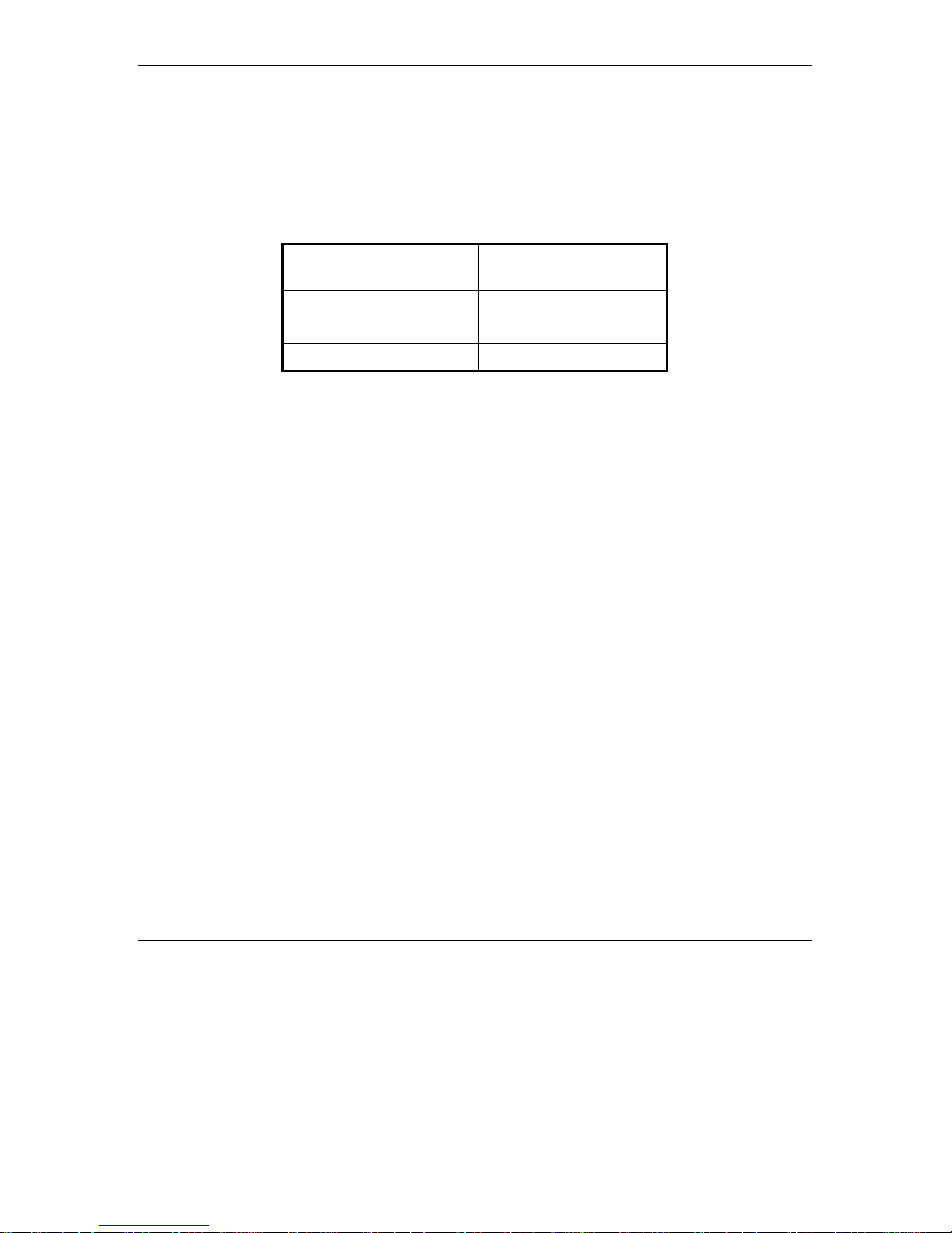
1. If the average RSSI reading using the Continuous Link Quality Display (se e Sec tion 4.1) is
lower than 65, the unit should be configured in accordance with the following table:
RSSI Recommended
Maximum Data Rate
RSSI > 65 3Mbps
53 < RSSI < 65 2Mbps
RSSI < 53 1Mbps
2. From the
Maximum Data Rate
• Type 3 (3Mbps) if the RSSI reading is higher than 65 units.
• Type 2 (2Mbps) if the RSSI reading is between 53 to 65 units.
• Type 1 (1Mbps) if the RSSI reading is lower than 53 units.
3. Reset the unit for the new configuration to become effective
See Appe ndix C for more details on the Maximum Data Rate pa rameter.
main menu
, type 3 to access the
menu.
Basic Configuration
menu. T ype 5 to access the
BreezeACCESS II Series 14 SU-R Installation Manual
Page 21
Verifying Proper Operation
6. VERIFYING PROPER OPERATION
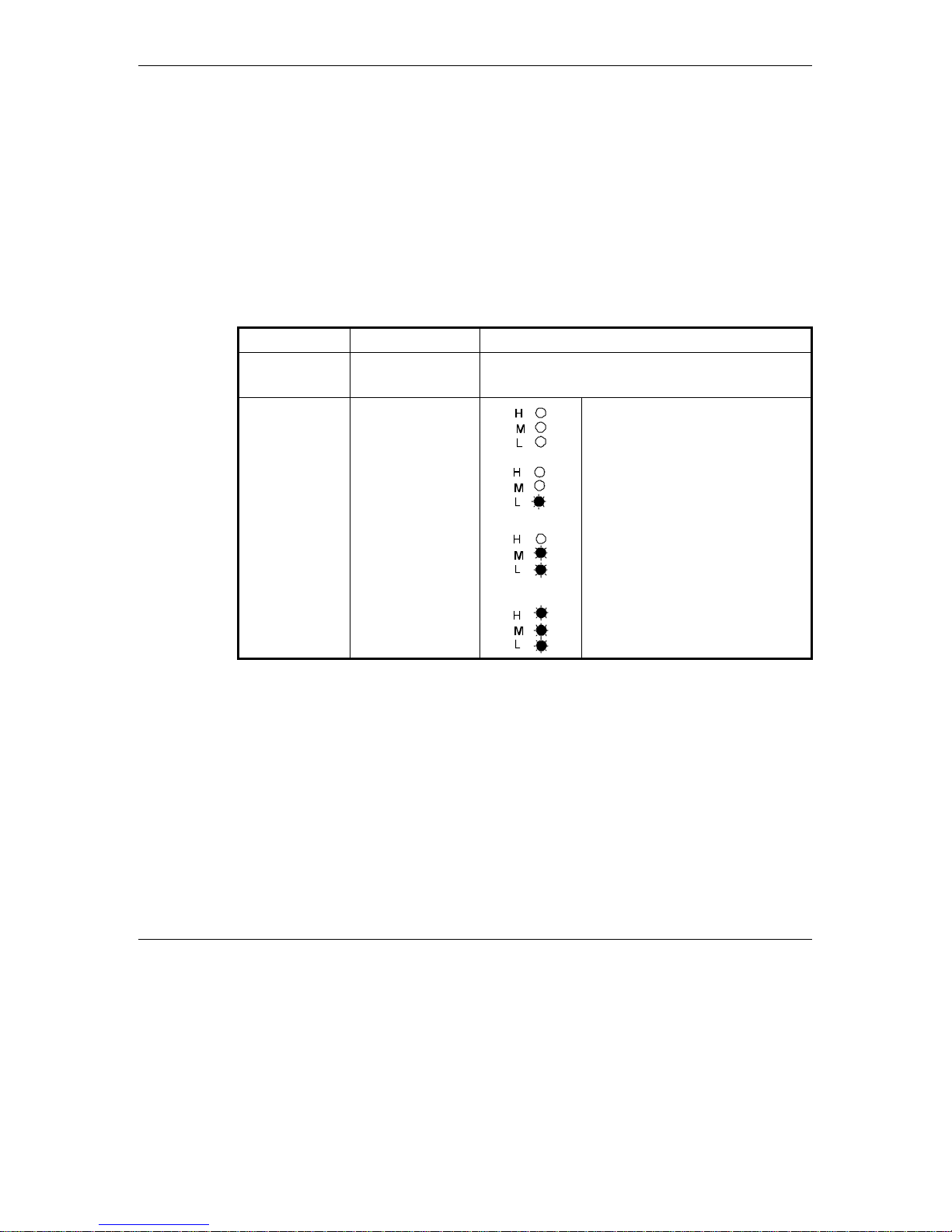
6.1 Checking the LEDs
After completing the installa tion, the system starts ope ration. T o v erify prope r opera tion, view the
LEDs located on the front pane l of the unit. Table 6-1 lists the various LED states .
Table 6-1. SU LEDs
Name Description Functionality
POWER Power supply On – After successful power up
Off – Power off
H, M, L Quality of
received RF
signal
Very low quality reception or not
synchronized with Access Unit.
Low quality reception (usually
enabling 1Mbps traffic).
Medium quality reception (usually
enabling 2 Mbps traffic).
High quality reception (usually
enabling 3 Mbps traffic).
6.2 Verifying the Ethernet Connection
Once you have connected the unit to an Ethernet outlet, verify that the Ethernet
Integrity indicator (the yellow LED embedded in the Ethernet connector) is on,
indicating that the unit is connected to an Ethernet segment. The Ethernet Activity
indicator (the green embedded LED) should blink whenever the unit receives or
transmit traffic on the Ethernet port.
SU-R Installation Manual 15 BreezeACCESS II Series
Page 22

Verifying Proper Operation
6.3 Verifying Data Connectivity
From the user’s PC or from a portable PC connected to the unit, ping the Access Terminal, or try
to connect to the Internet.
6.4 Verify ing Telephone Connectivity (units with voice support)
To verify co rrect op era tion of the telephone, a tes t tele phone with the default telephony
parameters and a known IP address should be connected to the system (the location of the test
telephone is determined by the sys te m administrator).
Perform the following steps to verify telep hone connectivity:
1. Use IP dialing to call the test telephone: dial * followed by the 12-digit IP addre s s of the test
telephone. Verify connectivity. During the c onversation, verify that other party has your IP
address.
2. After terminating the call, the other party should use the test telephone to call your IP
address and verify that the telephone, including the ringing c ircuits, functions properly.
BreezeACCESS II Series 16 SU-R Installation Manual
Page 23

Specifications
7. SPECIFICATIONS
7.1 Radio
Frequency 2.4 GHz ISM band
Radio Access Method FH-CDMA
Operation Mode Time Division Duplex
Channel Bandwidth 1 MHz
Output Power (at antenna port) 27 dBm typical. (can be reduced to 17 dBm-SW controlled)
Antenna Gain A model: 2 X 3 dBi Omni Antennas (OCX connector)
A7 (UNI-7): 7 dBi (including 3 m cable w/ OCX connector)
Sensitivity 1Mbps -91
(dBm at antenna port, BER 1E10-6) 2Mbps -83
3Mbps -75
Data Rate 3Mbps max
Modulation Multilevel GFSK
7.2 Data Communication
Standard Compliance IEEE 802.3 CSMA/CD
7.3 Voice Communic ation (units wi th voic e support)
Protocol H.323 Voice over IP compliant
Compression G.723 6.3 Kbps compression, G.729 8 Kbps compression,
G.711 64 Kbps transparent
Echo Cancellation G.168, G.131
SU-R Installation Manual 17 BreezeACCESS II Series
Page 24

Specifications
7.4 Configur ation and Manageme nt
Local Management Via MON port, Monitor program using terminal emulation
Remote Management SNMP, Telnet, TFTP
Remote Management Access From Wired LAN, Wireless Link
SNMP Agents MIB II, Bridge MIB, Private MIBs
Accounting RADIUS compatible client
Security Authentication and filtering
Software upgrade TFTP download
7.5 Interfaces
RF (Antenna) 2 x OCX jacks (A special OCX to SMA adapter is available)
Ethernet 10Base-T (RJ-45)
Telephone (units with voice) RJ-11 standard Plain Old Telephone System (POTS) interface
Monitor 3-pin low profile
Power DC socket for a power transformer
7.6 Electrical
External power Supply 100-250 VAC, 50-60 Hz, 0.5 A
Input voltage 5VDC
7.7 Mechanical
Without antenna and power
supply
BreezeACCESS II Series 18 SU-R Installation Manual
Page 25

7.8 Environmental
Specifications
Operating Temperature
Operating Humidity 5%-95% non condensing
0°C to 40°C
7.9 Standards Compliance, General
EMC FCC part 15, EN 300 826
Safety UL 1950, EN 60950
Environmental ETS 300 019
SU-R Installation Manual 19 BreezeACCESS II Series
Page 26

Page 27

Appendix A. Using Telnet
Appendix A. Using Telnet
Use the following procedure to connect to BreezeACCESS units via a Telnet session.
1. Connect the PC to the Ethernet port of the unit (or the hub to which the unit is connected)
using a straight Ethernet cable. If you connect the PC directly to a unit that is normally
connected to a hub, use a crossed Ethernet cable. You may also connect the PC to any
Ethernet port on the network and communicate with the unit to be mana ged via the wired or
wireless media.
2. Make sure that the PC’s IP parameters (IP address and subnet mask) are configured to
enable connectivity with the unit.
3. Start the Telnet application by se le cting
, Run and then typing Telnet in the Run
dialog box.
4. Select Connect-Remote System from the Telnet window menu. The following dialog box is
displayed.
5. In t h e
SU-R Installation Manual 21 BreezeACCESS II Series
Host Name
field, enter the IP address of the unit to be managed.
Page 28
Appendix A. Using Telnet
6. Set the
7. Set the
Port
field to Te lnet (this is the default).
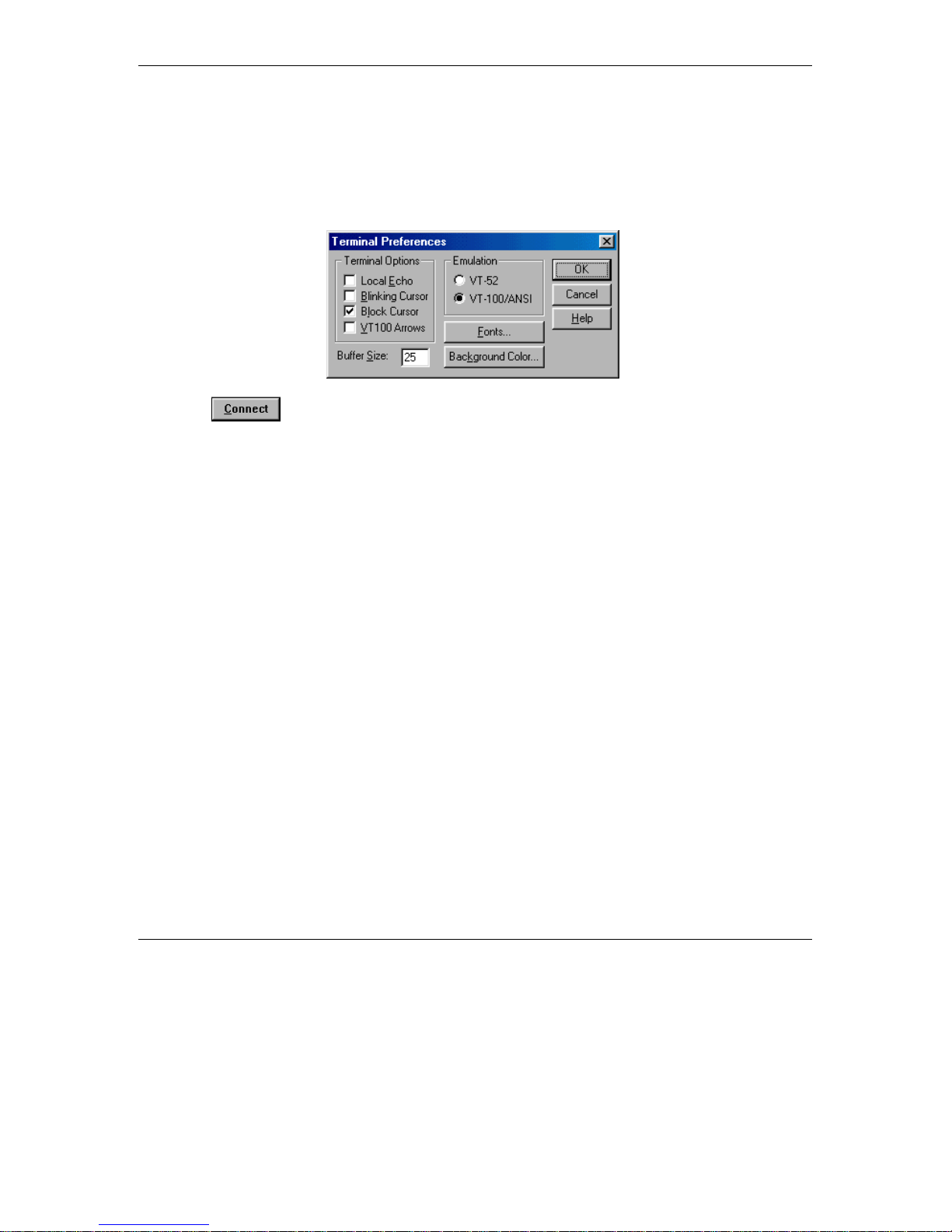
Terminal Type
to VT100 (this is the default). If the VT100 option in not available, do
the following. Select Terminal-Preferences from the Telnet window menu and click the VT100/ANSI radio button (as shown below).
8. Click in the Connect dialog box. The Select Access Level of the Monitor program
should be displayed.
To exit the Telnet session, choose
Disconnec
t from the
Connect
menu. (The session is terminated
automatically, after a s pe cific time of inactivity determined by the Log-out Timer).
BreezeACCESS II Series 22 SU-R Installation Manual
Page 29

Appendix B. Basic Parameters
Appendix B: Basic Parameters
IP Address –
•
(4 x 3 digit octets, separated by dots). The default IP Address is 010. 000. 000. 001.
Subnet Mask –
•
subnet mask (4 x 3 digit octets, separated by dots). T he default mask is 255.000.000. 000.
Defaul t Gateway Address –
•
and allows entry of a ne w default gateway address (4 x 3 digit octets, separated by dots ). T he
default gateway address is 000. 000. 000. 000.
DHCP Client
•
DHCP Options
⇒
Protocol) support, and allows se lecting a new operation mode. T he available options are:
Disable
∗
DHCP Only –
∗
Address, Subnet Mask and Default Gateway Address).
Displays the current IP address of the unit and allows entry of a new IP addres s
Displays the current subnet mask of the unit and allows e ntry of a new
Displays the current address of the default gateway of the unit
– Displa ys the current status of the DHCP (Dynamic Host Configuration
– Use manual procedure for configuring the IP parameters.
Search for a DHCP Server and obtain the IP parameters from it (IP
Automatic –
∗
Search for a DHCP Server for configuration of the IP parameters. If a
DHCP Server is not found within approximately 40 s ec onds, use the currently
configured IP parameters.
The default is Dis a ble .
Access to DHCP
⇒
- To define the port through which the unit is allowed to communicate
with a DHCP server. The options are the following:
∗ From Wlan Only
∗ From Ethernet Only
∗ From Both Ethe rnet & Wlan
The default for an Acces s Unit is From Ethernet Only. The default for a Subsc riber Unit is
From Wlan Only.
ESS ID
•
– The ESSID (Extende d Service Set ID) of the unit (up to 32 printable ASCII
characters). The ESSID is a string used to identify a wireless network. It prevents the
unintentional merging of two co-located wireless networks. A n SU can only as s o cia te with an
AU that has an identical ESSID. Use different ESSIDs to segment the wireless access network
and add security to your network. The default value is
SU-R Installation Manual 23 BreezeACCESS II Series
ESSID1
.
Page 30

Appendix B. Basic Parameters
Note:
•
The ESSID string is case-sensitive.
Maximum Data Rate
– Displa ys the current maximum d ata rate , and allows entry of a new
value for the maximum data rate.
BreezeACCESS
units operate at 1 Mbps , 2 Mbps or 3 Mbps . Under certain conditions
(compatibility rea sons or range/spee d tra d e -off), you may decide to limit the use of higher
rates. If the quality of the link is not good enough, it is recommended to decrease the value of
these pa rameters (t he higher the date ra t e , the higher the error rat e ). Otherwise, there is a high
probability that the unit will have to re transmit many frames several times be fore te mporarily
reducing the data rate. A high number of retransmissions reduces the overall throughput for
the selected SU as well as for all the other SUs served by the same AU.
The link quality can be estimated based on the RSSI measurement using the Continuous Link
Quality Dis pla y in the SU. If the me a s ured RSSI is less than a certain threshold, it is
recommended to decreas e the Maximum Data Rate of the SU in accordance with the following
table:
Recommended Maximum Data Rate 3Mbps 2Mbps 1Mbps
BreezeACCESS MMDS SU-I/ID RSSI>65 53<RSSI<65 RSSI<53
The default value is 3 Mbps. Allowed values are 1, 2 or 3 Mbps.
The AU learns the Maximum Data Rate used by each SU during the association process, and
uses this rate for transmissions to the spec ific SU.
Transmit Antenna
•
– Displays which antennas are used for transmission. SU-R units s upport
transmit antenna diversity (2 antennas). During reception, a BreezeACCESS unit that is
connected to two antennas dynamically selects the antenna where reception is optimal. In
contrast, if the transmit antenna diversity is e nabled, the unit selects the antenna from which it
will transmit before the actual transmission. It usually use s the antenna last u s ed for
succes s ful transmission. In installations whe re a model that can support antenna diversity is
connected to a single antenna, T ransmit Antenna Divers ity should be configured to transmit
only from that single antenna. Available selections are:
⇒ Us e Two A nt ennas
⇒ Use Antenna No. 1
⇒ Use Antenna No. 2
BreezeACCESS II Series 24 SU-R Installation Manual
Page 31

Appendix B. Basic Parameters
The default s ele c tion is
Use Antenna No. 1
for SU-R-A7 units where a single antenna is
connected to antenna port 1. For SU-R-A units with two omni antenna s s e lec t
Antennas
.
Use Two
SU-R Installation Manual 25 BreezeACCESS II Series
Page 32

Page 33

SU-R Installation Manual 27 BreezeACCESS II Series
 Loading...