

Page 1
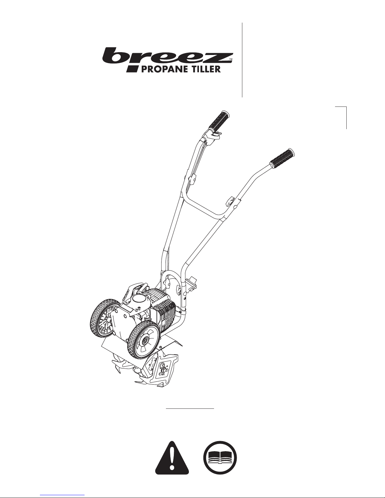
Operator's Manual
CAUTION ICON R1
READ OM ICON R1
Original Operating Instructions
Breez™ R2
High Compression
Propane Powered Tiller
SN
Get parts online at
www.breezpropanetillers.com
Includes Model:
21046
P/N: 21327
ECN: 10633
REV1: 01/30/15
© 2015 Ardisam, Inc.
All Rights Reserved
Page 2
Operator's Manual
Breez™ R2 Propane Powered Tiller
INTRODUCTION
Thank you for purchasing a Breez™ Propane Tiller. We have worked to ensure that this tiller meets the highest standards for
usability and durability. With proper care, your tiller will provide many years of service.
Please read this entire manual before installation and use. Breez™ reserves the right to change, alter or improve the product and
this document at any time without prior notice.
CONTENTS
Introduction/Content/Registration and Service ............................................................................................................................................................... 2
Warnings and Safety Precautions ....................................................................................................................................................................................... 3-6
Operation Precautions/Maintenance and Storage Precautions .................................................................................................................................. 6
Burns and Fires/Safety Decals .............................................................................................................................................................................................. 7-8
Features ...........................................................................................................................................................................................................................................9
Unpacking and Assembly .......................................................................................................................................................................................................10
Operation ............................................................................................................................................................................................................................... 10-12
Maintenance and Storage ................................................................................................................................................................................................ 13-14
Troubleshooting and Repair ............................................................................................................................................................................................14-15
Illustrated Parts Breakdown.............................................................................................................................................................................................16-20
15073 Border-Edger Kit Installation (Optional Accessory) ..........................................................................................................................................21
15290 Drag Stake Bracket Kit Installation (Optional Accessory) ...............................................................................................................................22
DK43 Dethatcher Kit Installation (Optional Accessory) ................................................................................................................................................23
Notes ...............................................................................................................................................................................................................................................24
Warranty ................................................................................................................................................................................................................................. 25-27
REGISTRATION AND SERVICE
Record the product model number and serial number in the space provided for
easy reference when ordering parts or requesting technical support. Excluding
emissions-related warranty items, the warranty is valid only if the completed
registration is received by Ardisam within 30 days of purchase. (SEE WARRANTY
SECTION FOR MORE INFORMATION) You can register your warranty online by
visiting www.breezpropanetillers.com, or by mailing it to: Ardisam Inc, 1160
8th Avenue, Cumberland, WI 54829. You may also call our Customer Service
department at (800) 345-6007 Mondays through Fridays from 8 a.m. to 5 p.m. CST.
OWNERSHIP RECORDS
Owner’s Name:
Owner’s Address:
City: State/Province: Zip Code/Postal Code:
Model Number: Serial Number:
Date of Purchase:
Notes:
Read and keep this manual for future reference. This manual contains important information on SAFETY, ASSEMBLY, OPERATION,
AND MAINTENANCE. The owner must be certain that all the product information is included with the unit. This information includes
the MANUAL, the REPLACEMENT PARTS and the WARRANTIES. This information must be included to make sure state laws and other
laws are followed. All persons to whom rent/loan this unit must have access to and understand this information. This manual should
remain with the product even if it is resold.
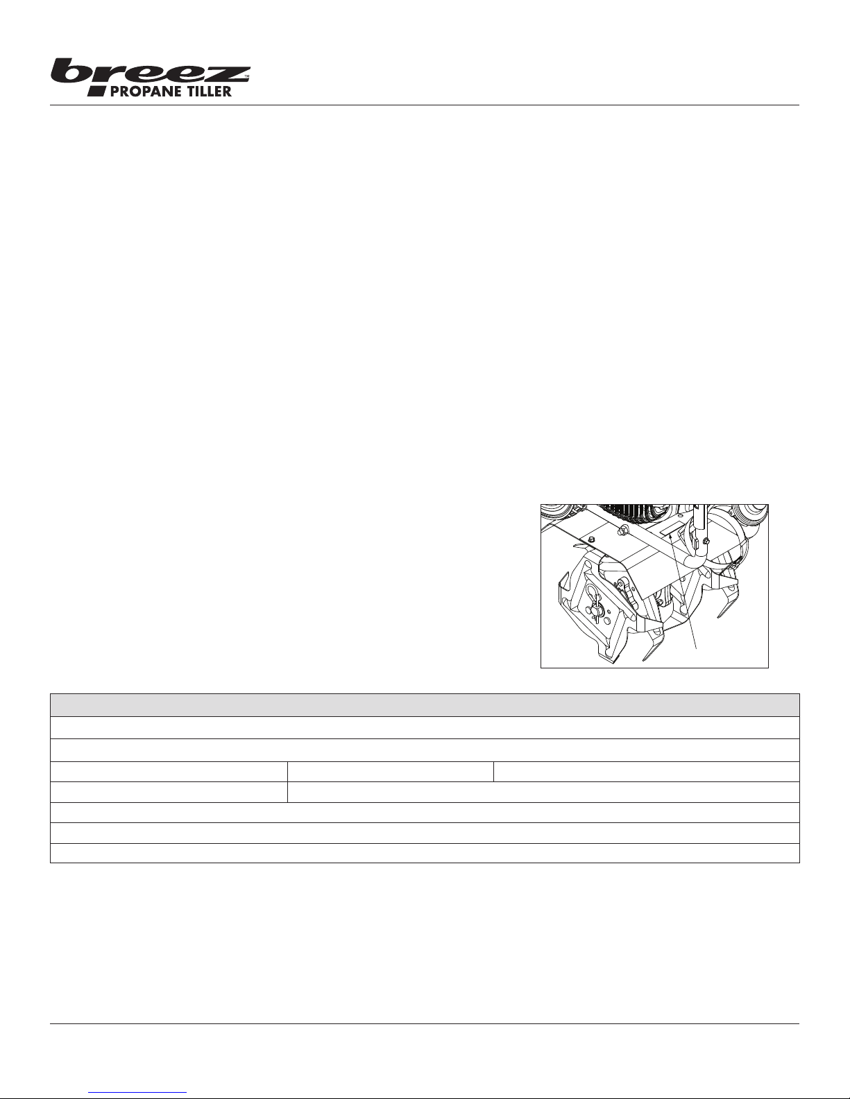
SERIAL NUMBER LOCATION
2
Check for parts online at www.breezpropanetillers.com or call 800-345-6007 M-F 8-5
Page 3
WARNINGS AND SAFETY PRECAUTIONS
Owner’s Responsibility
Accurate assembly and safe and eective use of the machine is
the owner’s responsibility.
• Read and follow all safety instructions.
• Carefully follow all assembly instructions.
• Maintain the machine according to directions and
schedule included in this Breez™ operator’s manual.
• Ensure that anyone who uses the machine is familiar
with all controls and safety precautions.
Special Messages
Your manual contains special messages to bring attention to
potential safety concerns, machine damage as well as helpful
operating and servicing information. Please read all the
information carefully to avoid injury and machine damage.
NOTE: General information is given throughout the
manual that may help the operator in the
operation or service of the machine.
THIS SYMBOL POINTS OUT IMPORTANT
SAFETY INSTRUCTIONS WHICH IF NOT
FOLLOWED COULD ENDANGER YOUR
PERSONAL SAFETY. READ AND FOLLOW ALL
INSTRUCTIONS IN THIS MANUAL BEFORE
ATTEMPTING TO OPERATE THIS EQUIPMENT.
Before Operating Engine:
Operator's Manual
Breez™ R2 Propane Powered Tiller
WARNING
WARNING INDICATES A HAZARD WHICH, IF NOT
AVOIDED, COULD RESULT IN DEATH OR SERIOUS
INJURY AND/OR PROPERTY DAMAGE.
CAUTION
CAUTION INDICATES YOUR EQUIPMENT CAN BE
DAMAGED IF THE SAFETY INSTRUCTIONS THAT
FOLLOW THIS SIGNAL WORD ARE NOT OBEYED.
IMPORTANT
INDICATES HELPFUL INFORMATION FOR PROPER
ASSEMBLY, OPERATION, OR MAINTENANCE OF
YOUR EQUIPMENT.
WARNING
CALIFORNIA PROPOSITION 65 WARNING
ENGINE EXHAUST FROM THIS PRODUCT
CONTAINS CHEMICALS KNOWN TO THE STATE OF
CALIFORNIA TO CAUSE CANCER, BIRTH DEFECTS,
OR OTHER REPRODUCTIVE HARM.
Please read this section carefully. Read entire operating and
maintenance instructions for this product. Failure to follow
instructions could result in serious injury or death. Operate
the machine according to the safety instructions outlined
here and inserted throughout the text. Anyone who uses this
machine must read the instructions and be familiar with the
controls.
Intended Use / Foreseeable Misuse
IMPORTANT: This is a motorized rotary tiller that works the
soil by means of rotating tines. It is pedestrian-controlled, but
not self-propelled, with a propane-fueled internal combustion
engine to power the tines. It shall not be used for any other
purpose.
WARNING
YOU MUST READ, UNDERSTAND AND
COMPLY WITH ALL SAFETY AND OPERATING
INSTRUCTIONS IN THIS MANUAL BEFORE
ATTEMPTING TO SETUP AND OPERATE YOUR
MACHINE.
FAILURE TO COMPLY WITH ALL SAFETY AND
OPERATING INSTRUCTIONS CAN RESULT IN LOSS
OF MACHINE CONTROL, SERIOUS PERSONAL
INJURY TO YOU AND/OR BYSTANDERS, AND RISK
OF EQUIPMENT AND PROPERTY DAMAGE. THE
TRIANGLE IN THE TEXT SIGNIFIES IMPORTANT
CAUTIONS OR WARNINGS WHICH MUST BE
FOLLOWED.
DANGER
Check for parts online at www.breezpropanetillers.com or call 800-345-6007 M-F 8-5
3
Page 4

Operator's Manual
Breez™ R2 Propane Powered Tiller
General Safety Rules
• Read, understand, and follow all instructions on the
machine and in the manual(s). Be thoroughly familiar
with the controls and the proper use of the machine
before starting.
• Use this equipment for its intended purpose only.
• Familiarize yourself with all of the safety and
operating decals on this equipment and on any of its
attachments or accessories.
• Do not put hands or feet near or under rotating parts.
• Only allow responsible individuals who are familiar
with the instructions to operate the machine. Do
not allow children to operate this machine. Do not
allow adults to operate the machine without proper
instruction.
• Thoroughly inspect the area where the machine
is to be used and remove all foreign objects. Your
equipment can propel small objects at high speed
causing personal injury or property damage. Stay
away from breakable objects, such as house windows,
automobile, greenhouses, etc.
• Wear appropriate clothing such as a long-sleeved
shirt or jacket. Also wear long trousers or slacks. Do
not wear shorts. Never wear sandals, sneakers, or
open shoes, and never operate the machine with bare
feet.
• Do not wear loose clothing or jewelry. They can get
caught in moving parts. Always keep hands, feet, hair
and loose clothing away from any moving parts on
engine and machine.
• Always wear safety goggles or safety glasses with side
shields when operating the machine to protect your
eyes from foreign objects which can be thrown from
the unit. Always wear a protective hearing device.
• Always wear work gloves and sturdy footwear. Wear
footwear that will improve footing on slippery
surfaces. Leather work shoes or short boots work well
for most people. These will protect the operator’s
ankles and shins from small sticks, splinters, and other
debris.
• It is advisable to wear protective headgear to prevent
the possibility of being struck by small ying particles,
or being struck by low hanging branches, twigs,
or other objects which may be unnoticed by the
operator.
• Do not operate the machine without proper guards or
other safety protective devices in place.
• See manufacturer’s instructions for proper operation
and installation of accessories. Only use accessories
approved by the manufacturer.
• Operate only in daylight or good articial light.
• Do not operate product when fatigued or under the
inuence of alcohol, drugs or other medication which
can cause drowsiness or aect your ability to operate
this machine safely.
• Never operate machine in wet grass. Always be sure
of your footing; keep a rm hold on the handle and
walk; never run.
• Watch for trac when operating near, or when
crossing roads.
• If the equipment should start to vibrate abnormally,
stop the engine (motor), disconnect the spark plug
wire and prevent it from touching the spark plug.
Check immediately for cause. Vibration is generally a
warning of trouble. If the noise or vibrations of the
machine increase, stop immediately and perform an
inspection.
• Never leave the machine unattended when the
engine is running. Remove the wire from the spark
plug.
• Regularly inspect the machine. Make sure parts are
not bent, damaged or loose.
• Temperature of muer and nearby areas may exceed
150° F (65° C). Allow muer and engine areas to cool
before touching. Never pick up or carry the machine
while the engine is running.
• Prolonged exposure to noise and vibration from propane
engine-powered equipment should be avoided. Take
intermittent breaks and/or wear ear protection from
engine noise as well as heavy work gloves to reduce
vibration in the hands.
• Keep all screws, nuts and bolts tight.
• Do not transport the machine from one place to
another with the engine running.
• When moving the packaged machine, always do so
with a partner.
• Check local regulations for age restrictions on use of
this machine.
Product-Specic Safety Rules
• Do not till above underground utilities, including
water lines, gas lines, electric cables, or pipes. Do
not operate the machine on terrain/soil with large
rocks and foreign objects which can damage the
equipment.
• After striking a foreign object, stop the engine.
Remove the wire from the spark plug. Inspect the
machine for damage. If damaged, repair before
starting and operating the machine.
• The tines of the tiller should not rotate when the
engine is idling. If it does rotate when engine is idling,
contact Breez™ for instructions.
• If an object becomes lodged in the tines, turn engine
o, remove the wire from the spark plug and secure,
allow to cool before attempting to remove the foreign
object.
• The clutch will transfer maximum power after about
two hours of normal operation. During this break-in
period clutch slippage may occur. The clutch should
be kept free of oil or other moisture for ecient
operation.
4
Check for parts online at www.breezpropanetillers.com or call 800-345-6007 M-F 8-5
Page 5
Operator's Manual
Breez™ R2 Propane Powered Tiller
WARNING
ENGINES GIVE OFF CARBON MONOXIDE, AN
ODORLESS, COLORLESS, POISONOUS GAS.
CARBON MONOXIDE MAY BE PRESENT EVEN IF
YOU DO NOT SMELL OR SEE ANY ENGINE EXHAUST.
BREATHING CARBON MONOXIDE CAN CAUSE
NAUSEA, FAINTING OR DEATH, IN ADDITION TO
DROWSINESS, DIZZINESS AND CONFUSION.
IF YOU EXPERIENCE ANY OF THESE SYMPTOMS,
SEEK FRESH AIR AND MEDICAL ATTENTION
IMMEDIATELY.
Engine Safety Precautions
If your product comes with a separate engine manual, be
sure to read and follow all safety and warning precautions
outlined there, in addition to any in this manual.
Preventing Carbon Monoxide Poisoning
• Always start and run engine outdoors. Do not start
or run engine in an enclosed area, even if doors or
windows are open.
• Never try to ventilate engine exhaust indoors. Carbon
monoxide can reach dangerous levels very quickly.
• Never run engine outdoors where exhaust fumes may
be pulled into a building.
• Never run engine outdoors in a poorly ventilated area
where the exhaust fumes may be trapped and not
easily taken away. (Examples include: in a large hole
or areas where hills surround your working area.)
• Never run engine in an enclosed or partially enclosed
area. (Examples include: buildings that are enclosed
on one or more sides, under tents, car ports or
basements.)
• Always run the engine with the exhaust and muer
pointed in the direction away from the operator.
• Never point the exhaust muer towards anyone.
People should always be many feet away from the
operation of the engine and its attachments.
• Do not change the engine governor settings or overspeed the engine.
Fires and Handling Fuel Safely
Use extra care in handling propane and other fuels. They are
ammable and vapors are explosive.
• When storing extra fuel cylinders be sure that they
are not stored in direct sunlight or in an area that can
exceed 120 degrees Fahrenheit (49 degrees Celsius).
Too much heat can cause cylinder to explode.
• Always replace fuel cylinder outside in a well
ventilated area. Never replace fuel cylinder indoors.
(Examples include: basement, garage, barn, shed,
house, porch, etc.)
• Never remove the fuel cylinder with the engine
running. Stop engine and allow to cool before
replacing fuel cylinder.
• Propane cylinders should be used until completely
empty.
CAUTION
HOT GASES ARE A NORMAL BYPRODUCT OF A
FUNCTIONING INTERNAL COMBUSTION ENGINE.
FOLLOW ALL SAFETY INSTRUCTIONS TO PREVENT
BURNS AND FIRES.
DO NOT ALTER/MODIFY ENGINE:
NEVER ALTER OR MODIFY THE ENGINE FROM
THE FACTORY. SERIOUS INJURY OR DEATH MAY
OCCUR IF ENGINE IS MODIFIED OR ALTERED.
WHEN WORKING ON OR REPLACING PARTS FOR
THE ENGINE OR PRODUCT, YOU MUST ALWAYS
FLIP THE ON/OFF SWITCH TO THE OFF POSITION.
• DO NOT REFILL DISPOSABLE PROPANE CYLINDERS.
Disposable tanks can explode when relled.
• Do not smoke near or while changing fuel cylinders.
• Allow fuel vapors to escape from the area before
starting engine.
• Do not change cylinder near appliances with pilot
lights, heaters, or other ignition sources.
• Always have an adult replace the fuel cylinder and
never allow children to handle fuel cylinders.
• Never allow an adult or anyone under the inuence of
drugs or alcohol to handle fuel cylinders.
• Do not put propane cylinders in baggage or transport
on trains or in aircraft.
• Empty propane cylinders must be disposed of
properly. Consult local regulations for disposal and
recycling.
• Follow all warnings on cylinder in addition to notes
above.
Preparation
• Dress appropriately when operating the tiller. Always
wear sturdy footwear. Never wear sandals, sneakers
or open shoes, and never operate the tiller with
bare feet. Do not wear loose clothing that might get
caught in moving parts.
• Carefully inspect the area to be tilled and remove
all foreign objects. Do not till above underground
water lines, gas lines, electric cables, or pipes. Do not
operate the tiller in soil with large rocks and foreign
objects which can damage the equipment.
• Disengage all clutches and leave control lever in the
neutral position before starting the engine.
• Handle fuel with care; it is highly ammable.
a. Use an approved fuel cylinder.
b. Never replace fuel cylinder with a running engine or
hot engine.
c. Replace fuel cylinder outdoors with extreme care.
Never replace fuel cylinder indoors.
d. Replace fuel cylinder securely before restarting.
Check for parts online at www.breezpropanetillers.com or call 800-345-6007 M-F 8-5
5
Page 6
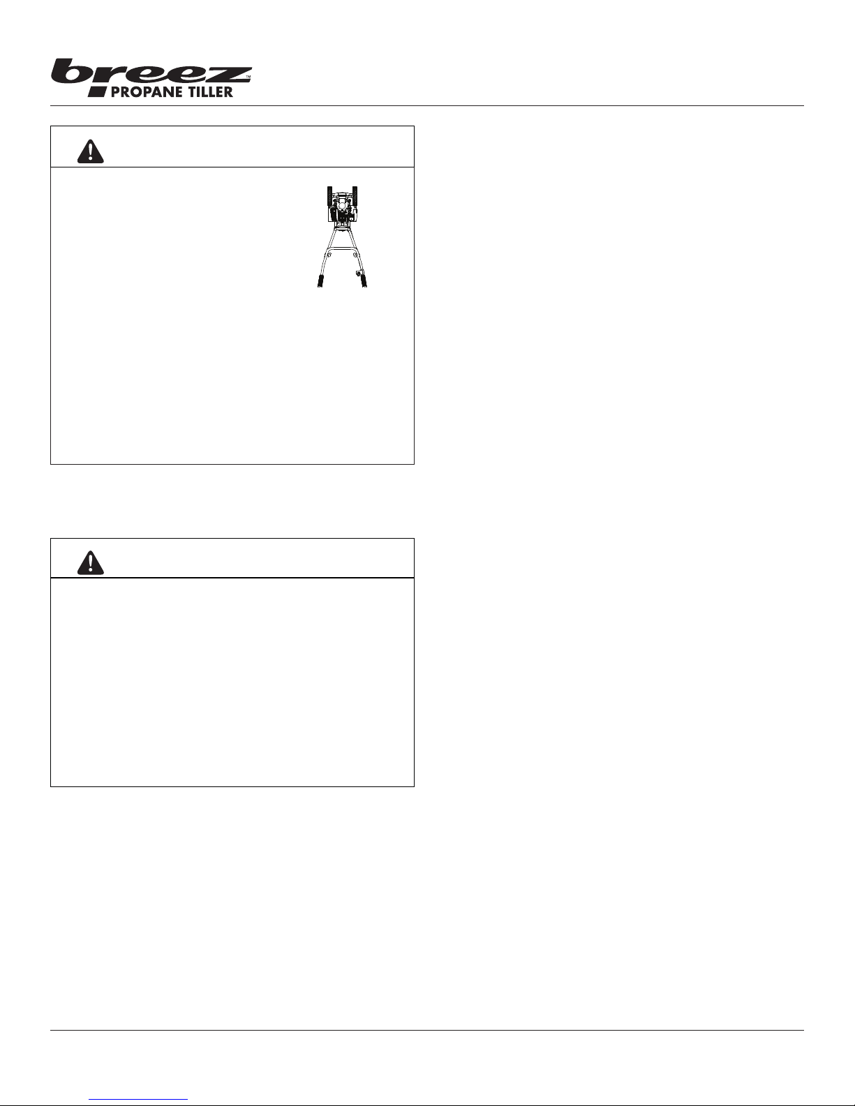
WARNING
THE RIGHT AND LEFT SIDES OF
YOUR TILLER ARE DETERMINED
FROM THE OPERATING POSITION
AS YOU FACE THE DIRECTION OF
FORWARD TRAVEL.
THE 4CYCLE ENGINE USES 10W30 MOTOR OIL.
DO NOT USE WITHOUT OIL OR ENGINE DAMAGE WILL
OCCUR.
THIS IS A MOTORIZED TILLER THAT WORKS THE SOIL
BY MEANS OF ROTATING TINES. IT IS PEDESTRIAN
CONTROLLED, BUT NOT SELFPROPELLED, AND
USES A PROPANEFUELED INTERNAL COMBUSTION
ENGINE TO POWER THE TINES. IT SHALL NOT BE USED
FOR ANY OTHER PURPOSE.
L
R
Operator's Manual
Breez™ R2 Propane Powered Tiller
• Use extreme caution when operating on or crossing
gravel drives, walks, or roads. Stay alert for hidden
hazards or trac.
• After striking a foreign object, stop the engine,
remove the wire from the spark plug, thoroughly
inspect the tiller for any damage, and repair the
damage before restarting and operating the tiller.
• If vegetation clogs the tines, stop the engine and
disconnect the spark plug wire before removing
vegetation by hand.
• If the unit should start to vibrate abnormally, stop the
engine and check immediately for the cause. Vibration
is generally a warning of trouble.
• Do not run engine indoors; exhaust fumes are deadly.
• Do not overload the machine capacity by attempting
to till too deep at too fast of a rate.
• Never operate the tiller without good visibility or
light.
• Take all possible precautions when leaving the
machine unattended. Disengage throttle control,
stop the engine, wait for all moving parts to stop, and
make certain guards and shields are in place.
• When leaving the operating position for any reason:
- shut o the engine.
- wait for all moving parts to stop.
CAUTION
HOT GASES ARE A NORMAL BYPRODUCT OF A
FUNCTIONING INTERNAL COMBUSTION ENGINE.
FOLLOW ALL SAFETY INSTRUCTIONS TO PREVENT
BURNS AND FIRES.
DO NOT ALTER/MODIFY ENGINE:
NEVER ALTER OR MODIFY THE ENGINE FROM
THE FACTORY. SERIOUS INJURY OR DEATH MAY
OCCUR IF ENGINE IS MODIFIED OR ALTERED.
WHEN WORKING ON OR REPLACING PARTS FOR
THE ENGINE OR PRODUCT, YOU MUST ALWAYS
FLIP THE ON/OFF SWITCH TO THE OFF POSITION.
OPERATION PRECAUTIONS
• Do not operate tiller under the inuence of alcohol or
drugs.
• Never operate tiller without guards, covers, and hoods
in place.
• Keep hands, feet, and clothing away from rotating
parts. Keep clear of tiller tines at all times.
• Tines rotate when tiller is engaged; tines rotate when
the drive safety control lever is pulled up. Releasing
the drive safety control lever to neutral stops the
tines.
MAINTENANCE AND STORAGE PRECAUTIONS
• Keep machine, attachments and accessories in safe
working condition.
• Check shear bolts, engine mounting bolts and other
bolts at frequent intervals for proper tightness to be
sure the equipment is in safe working condition.
• To prevent accidental starting, always disconnect and
secure the spark plug wire from the spark plug before
performing tiller maintenance.
• Never run the engine indoors. Exhaust fumes are
deadly.
• Never store equipment with fuel cylinder attached
inside a closed building where fumes may reach an
open ame or spark. Allow the engine to cool before
storing in any building.
• Always refer to the operator’s guide instructions for
important details if the tiller is to be stored for an
extended period.
6
Check for parts online at www.breezpropanetillers.com or call 800-345-6007 M-F 8-5
Page 7

Operator's Manual
Breez™ R2 Propane Powered Tiller
BURNS AND FIRES
The muer, muer guard and other parts of the engine become
extremely hot during the operation of the engine. These parts
remain extremely hot after the engine has stopped.
Prevention of Burns and Fires
• If you smell propane (identied by a sour, rotten
egg smell) do not start or run the engine. If there is
a build up of propane, leave the area immediately. If
necessary, call the local re department for assistance.
• Do a visual inspection of the propane tank, hose, and
tting seals before connecting the propane cylinder
to the engine. Do not connect a propane cylinder that
has damaged or missing seals.
• Always disconnect the regulator hose from the
propane cylinder before transporting or storage.
• Use a protective cap on the propane cylinder when
not attached to the engine. This will help keep the
cylinder valve clean.
• Do not over tighten propane cylinder when attaching
to fuel line. Damage to regulator or propane cylinder
seals can occur.
• Check for suspected propane leaks with soapy water
on connections. If bubble are observed, inspect and
retighten tting. Repair all leaks before use.
• Use caution when handling propane. Propane if
ammable.
• Never remove the muer guard from the engine.
• Never touch the muer guard because it is extremely
hot and will cause severe burns.
• Never touch parts of the engine that become hot after
operation.
• Always keep materials and debris away from muer
guard and other hot parts of the engine to avoid res.
Children and bystanders
Tragic accidents can occur if the operator is not alert to the
presence of children and/or bystanders. Never assume that
others will remain where you last saw them.
• Keep the area of operation clear of all persons, especially
small children and pets. Keep children under the
watchful care of a responsible adult.
• Be alert and turn machine o if children enter the area.
• Before and while moving backwards, look behind and
down for small children.
• Never allow children to operate the machine.
• Use extra care when approaching blind corners, shrubs,
trees, or other objects that may obscure vision.
Service
• Always stop the engine whenever you leave the equipment,
before cleaning, repairing or inspecting the unit. Engine
should be turned o and cool. Never make adjustments or
repairs with the engine (motor) running. Flip the ON/OFF
switch to the OFF position to prevent accidental starting.
• Always wear eye protection when you make adjustments or
repairs.
• Keep all nuts and bolts tight and keep equipment in good
condition.
• Never tamper with safety devices. Check their proper
operation regularly.
• When servicing or repairing the machine, do not tip the
machine over or up unless specically instructed to do so in
this manual. Service and repair procedures can be done with
the machine in an upright position. Some procedures will be
easier if the machine is lifted on a raised platform or working
surface.
• To reduce re hazard, keep machine free of grass, leaves or
other debris build-up. Clean up oil or fuel spillage. Allow
machine to cool before storing.
• Stop and inspect the equipment if you strike an object.
Repair, if necessary, before restarting.
• Clean and replace safety and instruction decals as necessary.
• To guard against engine over-heating, always have engine
debris lter mounted and clean.
• Inspect machine before storage. When not in use, ip the
ON/OFF switch to the OFF position and store indoors in a
dry place locked or otherwise inaccessible to children.
• Use only original equipment parts from Breez™, including
all nuts and bolts.
SAFETY DECALS
This tiller has been designed and manufactured to provide
you with the safety and reliability you would expect from an
industry leader in outdoor power equipment manufacturing.
Reading this manual and the safety instructions it contains will
provide you with the necessary basic knowledge to operate
this equipment safely and eectively. We have placed safety
decals on the tiller to remind you of some of this important
information while you are operating the unit.
These important safety decals are illustrated on the next page,
and are shown here to help familiarize you with the location
and content of the safety messages you will see as you
perform normal tilling operations. Please review these decals
now, and if you have any questions regarding its meaning or
how to comply with these instructions, reread the complete
safety instruction text in this manual.
Check for parts online at www.breezpropanetillers.com or call 800-345-6007 M-F 8-5
7
Page 8
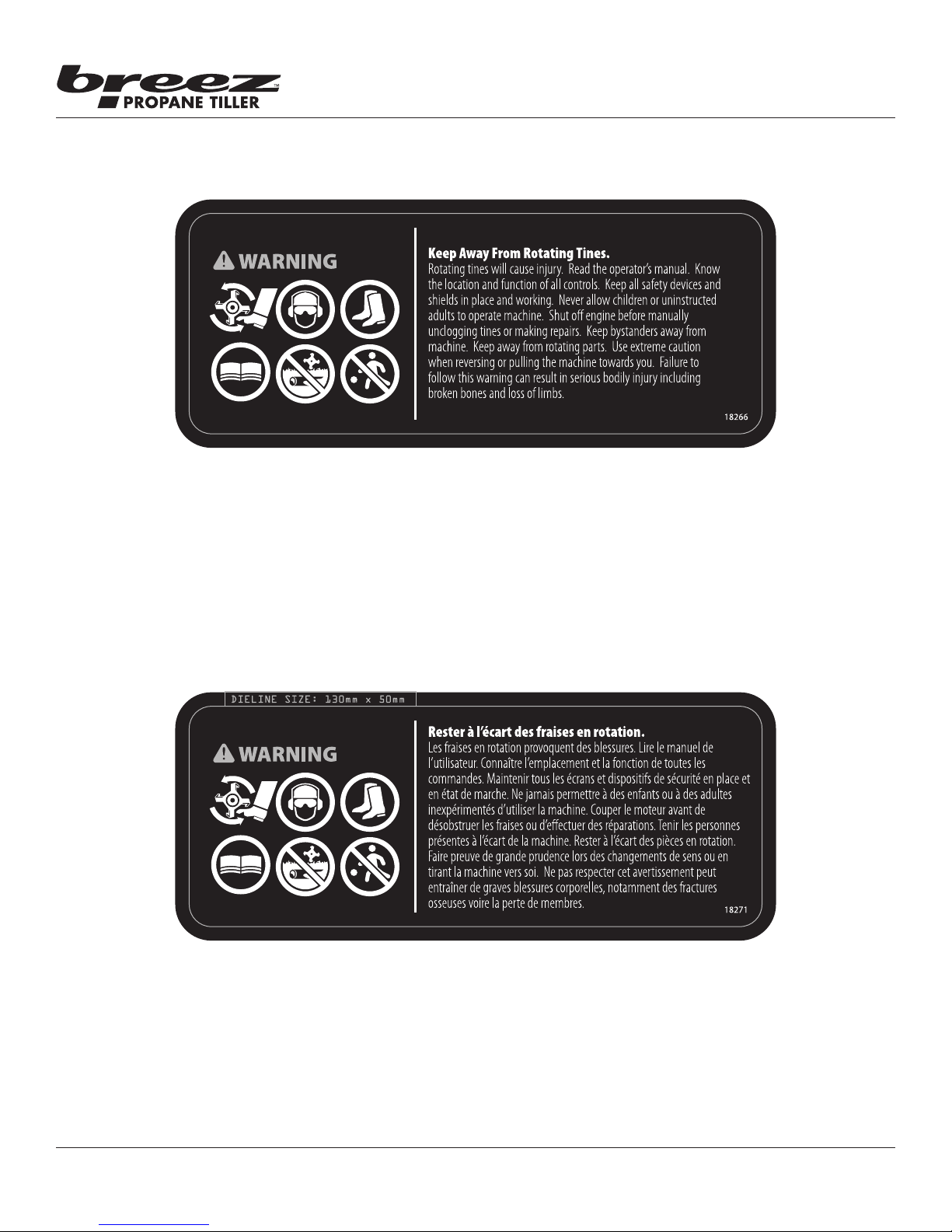
Part No. 18266
Tiller Warning Decal
Tine Shield Decal English
Operator's Manual
Breez™ R2 Propane Powered Tiller
8
Part No. 18271
Tiller Warning Decal
Tine Shield Decal French
Check for parts online at www.breezpropanetillers.com or call 800-345-6007 M-F 8-5
Page 9
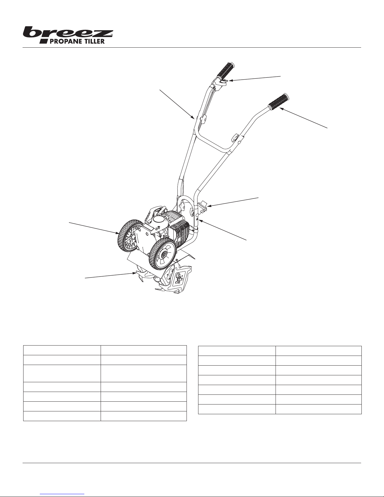
FEATURES
STURDY U-TURN™
HANDLEBAR STRUCTURE
Operator's Manual
Breez™ R2 Propane Powered Tiller
VARIABLE SPEED
THROTTLE CONTROL
LEVER WITH ON/OFF
SWITCH
KNOBBY
COMFORT
GRIPS
PROPANE
REGULATOR
AND BOTTLE
MOUNT
FLIP-AND-FOLLOW™
WHEEL MOUNT
REPLACEABLE TINES
SPECIFICATIONS
ENGINE DISPLACEMENT 40cc
PROPANE CYLINDER SIZE* 16.4 oz. ( 465 gram)
OIL TYPE VIPER® 4-Cycle Engine Oil
10W-30 (P/N 13235)
FUEL TYPE Propane
SPARK PLUG CMR6A
SPARK PLUG GAP 0.028”
TRANSMISSION Gear Drive
ADJUSTABLE
HEIGHT
HANDLEBARS
GEAR RATIO 32:1
TILLING WIDTH 6” minimum - 10” maximum
TILLING DEPTH 8” maximum
MAX TINE SPEED 250 rpm
WHEEL SIZE 1.375 x 7.0 inch diameter
WEIGHT OF UNIT 33 lb
UNIT SIZE L X W X H 37” x 18” x 39”
* One 16.4 oz. propane cylinder provides up to one hour of continuous run time at full throttle. (Longer run times
possible at half throttle)
Check for parts online at www.breezpropanetillers.com or call 800-345-6007 M-F 8-5
9
Page 10
UNPACKING AND ASSEMBLY
Unpack Tiller
1. Carefully lift the tiller out of the box, remove any packing
material and cut any ties holding the handlebar pieces or
tines to the tiller assembly.
2. Find parts packet. Parts packet contains:
• 4 - T-Handle Nuts (4640)
• 4 - Curved Washers (4641)
• 4 - Handle Clamp Bolts (4642)
3. Find manual packet. Manual packet contains:
• 1 - Hair Pin (4652)
Assembly
1. Stand the tiller assembly upright with tines and wheels
on a level surface. DO NOT place the tiller on a high
surface where it can fall and cause property damage or
personal injury.
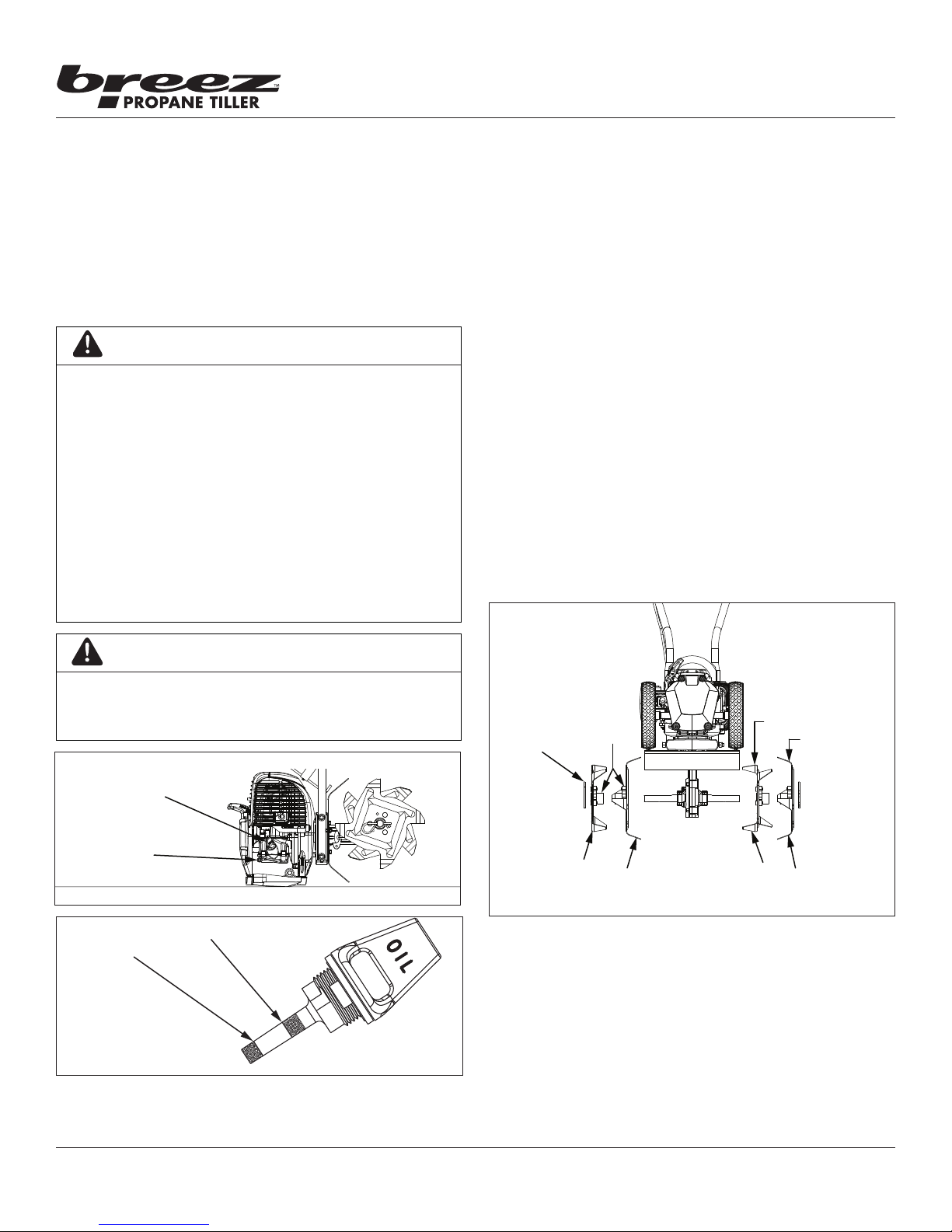
2. Slide inside tine B onto tine shaft.
3. Slide outside tine A onto end of tine shaft next.
4. Insert hair pin into hole at end of tine shaft to lock the
tines in place.
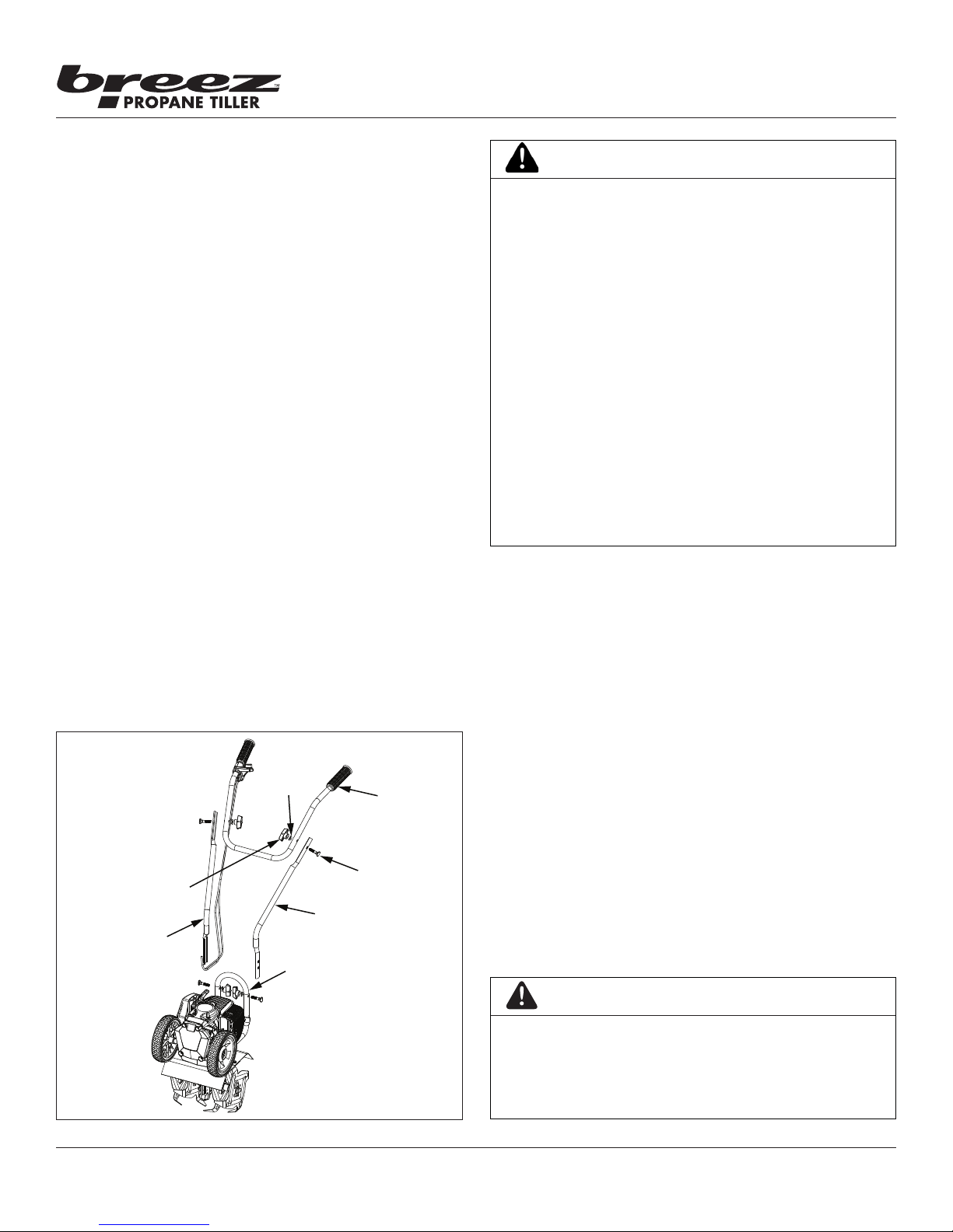
2. Using two T-handle nuts, two handlebar clamp bolts, and
two curved washers, attach the middle handlebars to the
lower handlebar that is already connected to the tiller
assembly. The middle handlebars can be installed in one
of two positions, one high and one low. SEE FIGURE 1
DO NOT overtighten the T-handle nuts.
3. Attach the upper handlebar to the middle handlebars
using the two remaining T-handle nuts, handle clamp
bolts, and curved washers. SEE FIGURE 1. DO NOT
overtighten the T-handle nuts.
CURVED
T-HANDLE
MIDDLE RIGHT
HANDLEBAR
FIGURE 1
WASHER
NUT
MIDDLE LEFT
HANDLEBAR
LOWER
HANDLEBAR
UPPER
HANDLEBAR
HANDLEBAR
CLAMP BOLT
Operator's Manual
Breez™ R2 Propane Powered Tiller
WARNING
DO NOT STORE ENGINE INDOORS WITH FUEL
CYLINDER ATTACHED. FUEL AND FUEL VAPORS
ARE HIGHLY FLAMMABLE.
NEVER REFILL FUEL CYLINDERS. USE ONLY
METAL, DISPOSABLE PROPANE FUEL CYLINDERS
APPROVED BY THE UNDERWRITER’S LABORATORY
U.L. OR THE AMERICAN SOCIETY FOR TESTING &
MATERIALS ASTM.
AN ADULT MUST ALWAYS HANDLE AND REPLACE
THE FUEL CYLINDER.
ALWAYS HANDLE PROPANE IN A WELL
VENTILATED AREA, OUTDOORS, AWAY FROM
FLAMES OR SPARKS.
NEVER RUN ENGINE INDOORS. EXHAUST FUMES
ARE DEADLY.
FAILURE TO FOLLOW THESE WARNINGS CAN
CAUSE DAMAGE TO EQUIPMENT AND INJURY TO
PERSONNEL.
OPERATION
PROPANE AND OIL
NOTE: Engine is shipped from factory without oil. You
must add engine oil before starting engine. If
engine is started without oil, engine may be
damaged beyond repair and will not be covered
by warranty.
Oil Quality
To operate the engine, we recommend using “VIPER®” brand
4-cycle oil (13235), included with each new Breez™ R2, or
an equivalent 10W-30 engine oil to ensure that the engine
operates correctly throughout the life of the engine. Use 16.4
oz (465 gram) disposable propane fuel cylinders.
Checking and Adding Oil
Be sure the engine is located on a level surface before
checking or relling oil. Proper position for checking oil level
or relling oil is face down on the wheel mount cover. It is
recommended to remove the wheels in order to ensure a level
surface. SEE FIGURE 2A
IMPORTANT
ENGINE MUST BE TIPPED FORWARD WHEN CHECKING
OIL LEVEL OR FILLING WITH OIL. FAILURE TO DO SO
CAN RESULT IN OVERFILLING THE ENGINE WITH OIL
WHICH WILL IMPAIR THE ENGINE’S PERFORMANCE.
10
Check for parts online at www.breezpropanetillers.com or call 800-345-6007 M-F 8-5
Page 11
Operator's Manual
HAIR PIN
Breez™ R2 Propane Powered Tiller
1. Clean around oil ll area.
2. Unscrew dipstick and wipe clean with cloth.
3. Reinsert dipstick (must be fully threaded for accurate
reading).
4. Unscrew and check dipstick. If no oil shows on the
dipstick, rell so that the oil level appears between the
low and high marks on the dipstick. SEE FIGURE 2B
5. Change oil if contaminated
CAUTION
ENGINE IS SHIPPED FROM FACTORY WITHOUT OIL. YOU
MUST ADD ENGINE OIL BEFORE STARTING ENGINE.
IF ENGINE IS STARTED WITHOUT OIL, ENGINE MAY BE
DAMAGED BEYOND REPAIR AND WILL NOT BE COVERED
BY WARRANTY.
NEVER STORE ENGINE WITH FUEL CYLINDER ATTACHED
INDOORS. FUEL AND FUEL VAPORS ARE HIGHLY
FLAMMABLE.
ONLY AN ADULT MUST ALWAYS HANDLE AND
REPLACE FUEL CYLINDER.
ALWAYS HANDLE PROPANE IN A WELL VENTILATED
AREA, OUTDOORS, AWAY FROM FLAMES OR SPARKS.
Operation Tips
1. The clutch will transfer maximum power after about two
hours of normal operation. During this break-in period
clutch slippage may occur. The clutch should be kept free
of oil and other moisture for ecient operation.
2. Till without placing excessive body weight on the unit.
The tiller operates most eciently with the weight of the
unit itself.
Preparing Engine For Starting
1. Make sure the engine crank case is lled with 3.7 oz
(110ml) of 10W-30 engine oil.
2. Screw a 16.4 oz (465 gram) disposable propane fuel
cylinder onto regulator assembly.
3. Insert fuel cylinder into holder and secure.
NOTE: The correct size disposable propane fuel cylinder
is approximately 3.875 inches (9.5 cm) in
diameter. Always use the correct size and type
specied. Use of the wrong propane cylinder can
cause damage to the engine. It is recommended
that you have at least one additional disposable
propane cylinder available to use as a backup.
IMPORTANT
DO NOT SPRAY WATER ON OR NEAR THE ELECTRONICS
OF THE TILLER AS THIS MAY RESULT IN DAMAGE TO
THE ELECTRICAL COMPONENTS.
WHEELS REMOVED FOR EASY OIL CHECKING
OIL DIPSTICK
OIL DRAIN
SCREW
FIGURE 2A
LOW OIL MARK
FIGURE 2B
BREEZ™ R2 ON LEVEL, HORIZONTAL SURFACE
HIGH OIL MARK
HUB
COLLARS
D
C
FIGURE 3
Tine Removal and Installation
To Remove Tines, do as follows: SEE FIGURE 3
1. Remove the hairpins from each end of the tine shaft.
2. Slide the four tines o the shaft.
To Install Tines
1. First slide the inside tines onto each end of the tine shaft.
One inside tine is stamped with a B and the other is
stamped with a C.
INNER TINE
OUTER TINE
B
A
Check for parts online at www.breezpropanetillers.com or call 800-345-6007 M-F 8-5
11
Page 12
Operator's Manual
Breez™ R2 Propane Powered Tiller
2. Slide the outside tine A and tine D onto each end of the
shaft next. The tines should be installed in the correct
order so that they are positioned left to right A, B, C, D,
as viewed from the user’s position on the tiller. Make sure
that the hub collars on both the right and left pairs of
tines face each other so that there is adequate spacing
between the tine blades.
3. Insert the hairpins into the holes at each end of the tine
shaft to lock the tines into place.
NOTE: Tines can be reversed so the pointed tip of the
tines are directed forward - for more aggressive
digging. In this arrangement, tines are positioned
left to right D, C, B, A as viewed from the user’s
position.
To reduce tilling width from 10” to 6”, remove both
outer tines and reinsert hairpins through the two
inner holes on the tine shaft to secure both inner
tines in place.
WARNING
MAKE SURE THE UNIT IS IN A STABLE POSITION
BEFORE PULLING THE STARTER HANDLE.
WHEN THE UNIT STARTS TO FIRE OR RUN, RETURN
BOTH HANDS TO THE HANDLE BAR POSITION TO
MAINTAIN CONTROL AND STABILITY OF THE UNIT.
STARTER ROPE CAN CAUSE AN UNANTICIPATED
JERK TOWARDS ENGINE. PLEASE FOLLOW
INSTRUCTIONS TO AVOID INJURY.
NEVER LEAVE ENGINE RUNNING WHILE
UNATTENDED. TURN OFF AFTER EVERY USE.
NEVER CARRY TILLER FROM ONE LOCATION TO
ANOTHER WHILE ENGINE IS RUNNING.
ALWAYS WEAR A PROTECTIVE HEARING DEVICE.
Starting and Stopping the Engine
• Move engine to a well ventilated area, outdoors, to
prevent carbon monoxide poisoning.
• Move to an area away from ames or sparks, to avoid
ignition of vapors if present.
• Remove all debris from air cleaner holes to ensure
proper air ow.
Engine Start:
Starting engine for rst time or after engine has cooled o or
after running out of fuel.
NOTE: The Breez™ R2 Propane Tiller does not require
choking or priming.
1. Set ON/OFF switch on handlebar to the ON position.
2. Hold handlebar rmly. Grasp starter handle with other
hand and pull out slowly, until there is tension as you
pull. Without letting starter handle retract, pull rope with
a rapid full arm stroke. Let it return to its original position
very slowly. Repeat this step every time the starter rope
is pulled until unit res or runs. When the engine res or
runs, engage the throttle.
NOTE: When attempting to start, DO NOT allow the recoil
to retract on its own, as it may snap back quickly
and cause injury. Repeat this step every time the
starter rope is pulled. Run at full throttle when
possible. Do not let unit idle for extended periods
of time.
Cold Warm-Up Procedure
When starting the engine in very cold weather, it may be
necessary to “feather” the throttle after starting. This will
allow the engine to warm up and reduce stalling.
NOTE: If the engine does not start due to excessive cold
weather conditions, replace the propane cylinder
with a new cylinder that has been stored in a
warm place.
WARNING
PRACTICE SAFETY AT ALL TIMES. ENGINE MUST
BE TURNED OFF AND ALLOWED TO COOL, AND
SPARK PLUG WIRE MUST BE DISCONNECTED
BEFORE ATTEMPTING ANY MAINTENANCE OR
REPAIR.
TO PREVENT ACCIDENTAL STARTING:
ENGINE MUST BE TURNED OFF AND COOL, AND
SPARK PLUG WIRE MUST BE REMOVED FROM
SPARK PLUG BEFORE CHECKING AND ADJUSTING
ENGINE OR EQUIPMENT.
TEMPERATURE OF MUFFLER AND NEARBY AREAS
MAY EXCEED 150° F 65° C. AVOID THESE AREAS.
CHECK TILLER OFTEN FOR LOOSE NUTS AND
BOLTS. KEEP THESE ITEMS TIGHTENED.
NEVER STORE ENGINE WITH FUEL CYLINDER
ATTACHED INSIDE A BUILDING. POTENTIAL
SPARKS MAY BE PRESENT FOR IGNITION OF FUEL
AND FUEL VAPORS.
AN ADULT MUST ALWAYS DO MAINTENANCE AND
REPAIR ON ENGINE AND TILLER.
ENGINE MUST BE SHUTOFF, COOL, AND SPARK
PLUG WIRE REMOVED BEFORE ANY REPAIR OR
MAINTENANCE CAN BE DONE.
12
Check for parts online at www.breezpropanetillers.com or call 800-345-6007 M-F 8-5
Page 13

Operator's Manual
Breez™ R2 Propane Powered Tiller
MAINTENANCE AND STORAGE
Steps For Working On Equipment
1. Turn engine switch to the OFF position.
2. Disconnect the spark plug wire from the spark plug.
3. Securely place the disconnected spark plug wire away
from the spark plug and any metal parts. This must
always be done or arcing may occur between spark plug
wire and metal parts.
4. Replace or repair the part on the tiller.
5. Check all parts that were repaired, or removed during
repair, that they are secure and t correctly.
NOTE: All repair parts must come from the factory. Never
replace parts that are not specically designed for
the tiller.
6. Reconnect the spark plug wire.
Tiller Maintenance
1. The transmission case has grease installed at the factory.
It is recommended that once a year the gear case be split
by a qualied service professional and the grease level
checked. Add a molylithium type grease only if level of
grease is below top of the gears. DO NOT OVERFILL.
2. Keep all screws, nuts, and bolts tight.
3. For cold weather operation, store the unit in a cool
environment. Transferring the unit from a cold to a warm
place can cause the build up of harmful condensation.
Engine Maintenance
Please read the maintenance schedule and observe these
recommendations to extend the life of your engine.
Good maintenance is essential for safe, economical, and
trouble-free operation. It will also help reduce air pollution.
To help you properly care for your engine, the following
pages include a maintenance schedule, routine inspection
procedures, and simple maintenance procedures using basic
hand tools. Other service tasks that are more dicult, or
require special tools, are best handled by professionals and
are normally performed by a technician or other qualied
mechanic.
Maintenance, replacement or repair of the emissions control
devices and systems may be performed by any non-road
engine repair establishment or individuals. However, items
must be serviced by an authorized dealer to obtain “no
charge” emissions control service.
The maintenance schedule applies to normal operating
conditions. If you operate your engine under unusual
conditions, such as sustained high-load or high-temperature
operation, or use in unusually wet or dusty conditions, consult
your servicing dealer for recommendations applicable to your
individual needs and use.
Maintenance Schedule
Every 8
hours
MAINTENANCE ITEM
Clean Engine and
Check Bolts & Nut
Air Filter Check X
(See Air Filter section)
Spark Plug
(Gap 0.028”)
(See Spark Plug section)
* Service more frequently under dusty conditions
Clean * X
Replace X X
Check/
Adjust
Replace X
(daily)
X
Every 20
hours or
seasonally
X
Each
Year
Spark Plug
The recommended spark plug is a NGK CMR6A. (40cc)
1. Check spark plug at the beginning of each season or
every 20 operating hours.
2. Disconnect the spark plug cap, and clean any debris from
around the spark plug area.
3. Remove spark plug and replace if any of the following
occur; pitted electrodes, burned electrodes, cracked
porcelain, or deposits around electrodes.
4. After analysis, seat spark plug and tighten with spark plug
wrench. Reconnect the spark plug wire.
• Reinstall original spark plug, tighten additional 1/2
turn.
• Installing new spark plug, adjust spark plug gap to
0.028” and tighten nger tight. Torque the spark plug
to 7.2 - 8.7 ft-lbs.
NOTE: A loose spark plug may overheat and damage
engine. An over tightened spark plug may damage
threads in the cylinder head.
Cooling Fins
Cooling ns, air inlets and linkages must be free from any
debris before each use.
CARBURETOR
Never tamper with factory setting of the carburetor.
Air Filter
Never run engine without air cleaner properly installed. Added
wear and engine failure may occur if air cleaner is not installed
on engine.
Service air cleaner every 3 months or after 20 hours of
operation. Clean lter daily in extremely dusty conditions.
Check for parts online at www.breezpropanetillers.com or call 800-345-6007 M-F 8-5
13
Page 14
BACK LATCH TABS
LATCH
FIBER FILTER
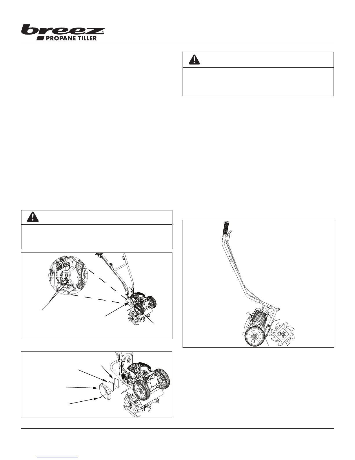
Step for Replacing and Cleaning Air Filter:
1. To remove air lter cover, unscrew the cover bolt with a
screw driver and gently pop out the front latch tab. The
cover then can be slid o the back latch tabs and away
from the engine. SEE FIGURE 4
2. Remove the foam lter and ber lter elements. Replace
with a new ber lter and a new oiled foam lter
(SEE FIGURE 5), or clean the original foam and ber
lters with warm water and mild soap. Remember to
thoroughly oil the foam lter with 30 or 40 weight motor
oil and squeeze out any excess oil before reinstalling it.
Make sure to press the foam lter evenly into place over
the ber lter to ensure that the foam is fully seated into
its sealed position.
3. Replace the air lter cover by rst connecting the back
latch tabs then swinging the cover, making sure the foam
lter block stays fully seated and in its proper position,
and connect the front latch tab so that it is secured into
place.
4. Screw the cover bolt back into place. Check that the
cover is securely attached by pulling slightly on the cover.
If the cover doesn’t move when pulled, it is secure.
Operator's Manual
Breez™ R2 Propane Powered Tiller
WARNING
NEVER STORE TILLER WITH FUEL CYLINDER
ATTACHED INSIDE AN ENCLOSED AREA OR
BUILDING. FUEL VAPORS CAN COLLECT AND
CAUSE A FIRE.
Transporting Your Tiller
1. After using the tiller and before transporting it, remove
the fuel cylinder from the bottle holder.
2. Disconnect the fuel cylinder from the regulator hose and
and cover with safety cap to prevent damage to the valve
seals.
Long-Term Storage
1. Remove the fuel cylinder from the bottle holder.
2. Disconnect the fuel cylinder from the regulator hose and
and cover with safety cap to prevent damage to the valve
seals.
3. Store tiller in the upright position. SEE FIGURE 6
4. Remove all debris from tiller tines and engine.
CAUTION
DO NOT TWIST AIR FILTERS WHEN CLEANING. ALWAYS
PRESS. TWISTING OR TOO MUCH FORCE CAN DAMAGE THE
FILTER ELEMENT.
AIR FILTER COVER
FIGURE 4
ELEMENT
FIGURE 5
FOAM FILTER
ELEMENT
AIR FILTER
COVER
COVER
BOLT
FRONT
TAB
FIGURE 6
TROUBLESHOOTING AND REPAIR
At Breez™, we build quality and durability into the design
of our products; but no amount of careful design by us, and
careful maintenance by you, can guarantee a repair-free life for
your Breez™ Tiller. Most repairs will be minor, and easily xed
by following the suggestions in the troubleshooting guide in
this section.
The guide will help you pinpoint the causes of common
problems and identify remedies.
14
Check for parts online at www.breezpropanetillers.com or call 800-345-6007 M-F 8-5
Page 15
For more complicated repairs, you may want to rely on your
retailer, an authorized service center or Breez™. Breez™ will
make the necessary repairs if a service center is not available. A
parts breakdown is located toward the end of this manual.
We will always be glad to answer any questions you have, or
help you nd suitable assistance. To order parts or inquire
about warranty, call or e-mail us using the contact information
found in this section.
Ordering Replacement Parts
Parts can be obtained from the store where the tiller was
purchased or direct from the factory. To order parts visit;
www. getearthquake.com or call 1-800-345-6007.
For other general questions, you can e-mail us at:
[email protected].
Please include the following information with your order:
1) Part numbers
2) Part description
3) Quantity
4) Model number and serial number
Spare Parts
Only use approved Breez™ spare parts.
Operator's Manual
Breez™ R2 Propane Powered Tiller
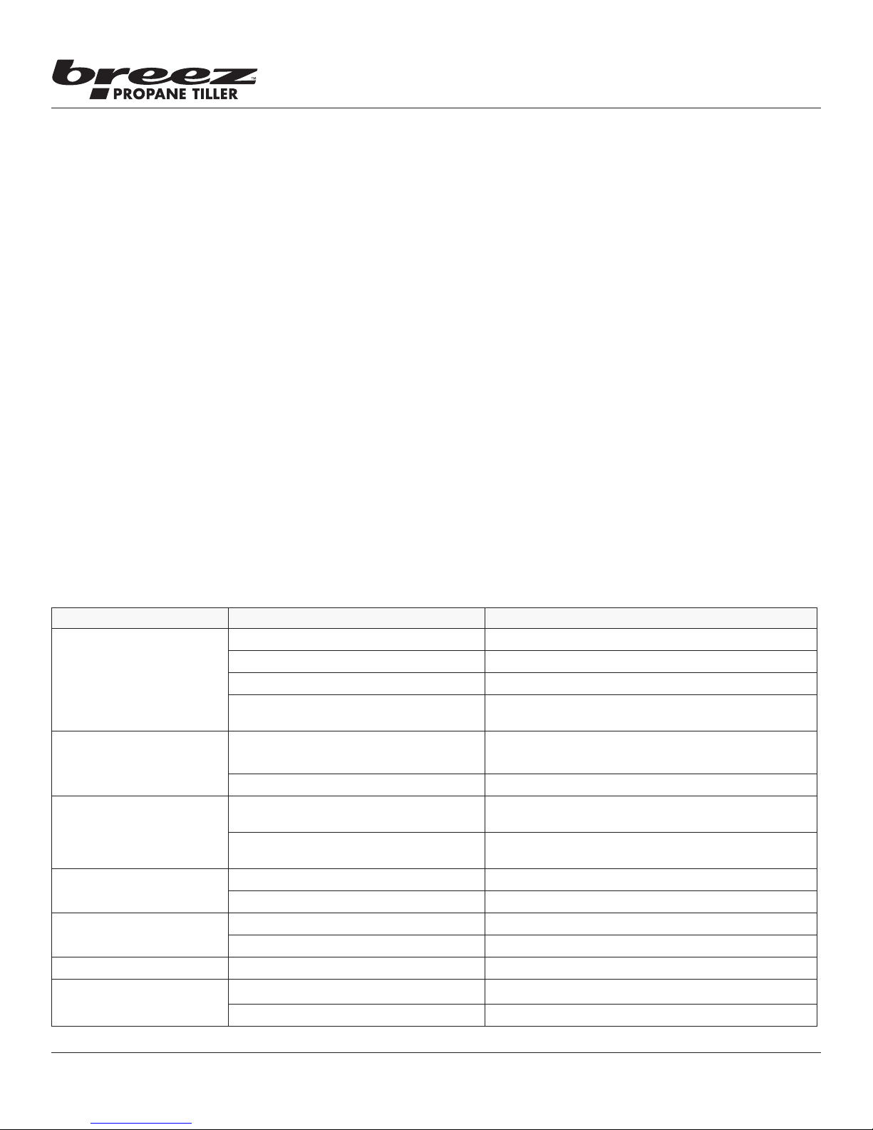
TROUBLESHOOTING GUIDE
PROBLEM POSSIBLE CAUSE REMEDY/ACTION
Engine will not start 1. Power switch o 1. Flip switch to ON position
2. Spark plug wire disconnected 2. Connect spark plug wire to spark plug
3. Out of fuel 3. Replace propane fuel cylinder
4. Spark plug wet, faulty or improperly
gapped
Engine runs rough, oods
1. Dirty air lter 1. Clean or replace air lter
during operation
2. Carburetor out of adjustment 2. Call customer service
Engine is hard to start 1. Spark plug wire loose 1. Make sure spark wire is securely attached to spark
2. Fuel too cold 2. Replace cylinder with one that has been stored in
Engine misses or lacks
power
1. Clogged air lter 1. Remove and clean or replace
2. Fouled spark plug 2. Replace spark plug
Engine runs, then quits 1. Clogged air lter 1. Remove and clean or replace
2. Carburetor out of adjustment or bad 2. Call customer service
Engine revs too high 1. Carburetor out of adjustment 1. Call customer service
Tines turn at idle 1. Idle speed too high 1. Adjust idle speed lower
4. Clean, replace or gap spark plug
plug
a warm location
2. Broken clutch spring 2. Replace both springs
Check for parts online at www.breezpropanetillers.com or call 800-345-6007 M-F 8-5
15
Page 16
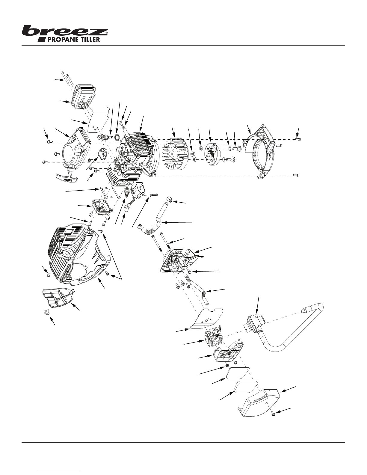
Operator's Manual
Breez™ R2 Propane Powered Tiller
ILLUSTRATED PARTS BREAKDOWN
28, 49
30, 50, 52
31
29, 50
17
16, 46
15, 46
1
27, 49
25
23, 48,
52
26, 49,
24
1
52
22, 48
1, 48
Engine Assembly
32
33
34
35
14, 44
13, 44
12, 45
36, 51
37, 51
11, 45
38, 51
39, 51
40
41
18, 47
21, 47
20, 47
19, 47
18, 47
8, 43
7, 43
6, 42
5, 42
4, 42
1, 45
3, 42
10, 44
9
2, 42
1, 42
16
Check for parts online at www.breezpropanetillers.com or call 800-345-6007 M-F 8-5
Page 17
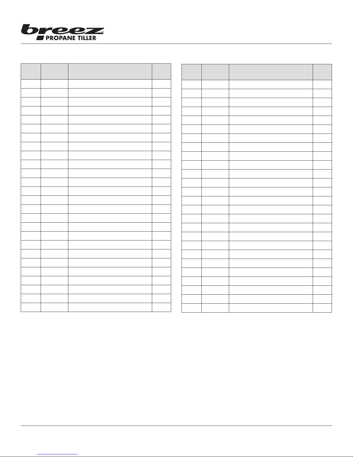
Operator's Manual
Breez™ R2 Propane Powered Tiller
ILLUSTRATED PARTS BREAKDOWN
ITEM
NO.
PART
NO.
DESCRIPTION QT Y.
Engine Assembly
1 10887 BOLT M5 X 0.8 X 16 MM PHILIPS 14
2 13197 AIR FILTER COVER 1
3 13198 AIR FILTER 1
4 17078 AIR FILTER FIBER 1
5 400020 NUT M5 X 0.8 MM TOPLOCK 2
6 17251 INTAKE BASE ASSEMBLY 1
7 16544 CARBURETOR PROPANE 1
8 13299 CARBURETOR GASKET 1
9 19169 REGULATOR HOSE ASSEMBLY 1
10 17252 CRANKCASE BREATHER HOSE 1
11 13328 CARBURETOR INSULATOR 1
12 17249 BOLT M5 X 0.8 X 70 MM HEX 2
13 13317 VALVE COVER BREATHER HOSE 1
14 13395 HOSE CLAMP 13.5 MM ID 2
15 13325 BOLT M4 X 0.7 X 20 MM PHILIPS 2
16 13252 IGNITION COIL 1
17 13243 SPARK PLUG NGK CMR6A 1
18 300471 BOLT M5 X 0.8 X 12 MM HEX 3
19 11041 ENGINE SHROUD BLACK 1
20 11043 ENGINE SHROUD CAP BLACK 1
21 11044 SCREW 3/16 X 1/2 INCH PHILIPS 1
22 13321 VALVE COVER 1
23 13324 VALVE COVER GASKET 1
24 13244 RECOIL CLUTCH 1
25 13194 RECOIL ASSEMBLY 1
26 13202 MUFFLER HEAT SHIELD 1
ITEM
NO.
PART
NO.
DESCRIPTION QT Y.
27 13200 MUFFLER 1
28 13181 BOLT M5 X 0.8 X 50 MM SOCKET 2
29 13196 DIPSTICK 1
30 15977 DIPSTICK GASKET 16MM ID 1
31 19919 BOLT M6 X 1.0 X 10 MM HEX 1
32 13320 WASHER M6 COPPER 1
33 13322 ENGINE BLOCK 1
34 13241 FLYWHEEL 1
35 300337 NUT M8 X 1.25 MM HEX FLANGE 1
36 300462 WASHER 15.8 X 8.4 X 1.6 MM 2
37 300413 CENTRIFUGAL CLUTCH 1
38 300449 WAVE WASHER 10 X 15 X 0.25MM 2
39 300450 BOLT M8 X 1.25 X 25 MM SHLDR 2
40 13239 MOUNT RING 1
W1200123
41
BOLT M5 X 0.8 X 16 MM SOCKET 3
42 13363 AIR FILTER KIT 1
43 21325 CARBURETOR PROPANE KIT 1
44 13394 BREATHER HOSES KIT 1
45 13390 CARBURETOR BRACKET KIT 1
46 13400 IGNITION COIL KIT 1
47 18497 ENGINE SHROUD KIT 1
48 13298 VALVE COVER KIT 1
49 13391 MUFFLER KIT 1
50 13393 DIPSTICK KIT WITH O-RING 1
51 11235 CLUTCH KIT 76.76 MM OD VIPER 1
52 13066 GASKETS KIT 1
Check for parts online at www.breezpropanetillers.com or call 800-345-6007 M-F 8-5
17
Page 18
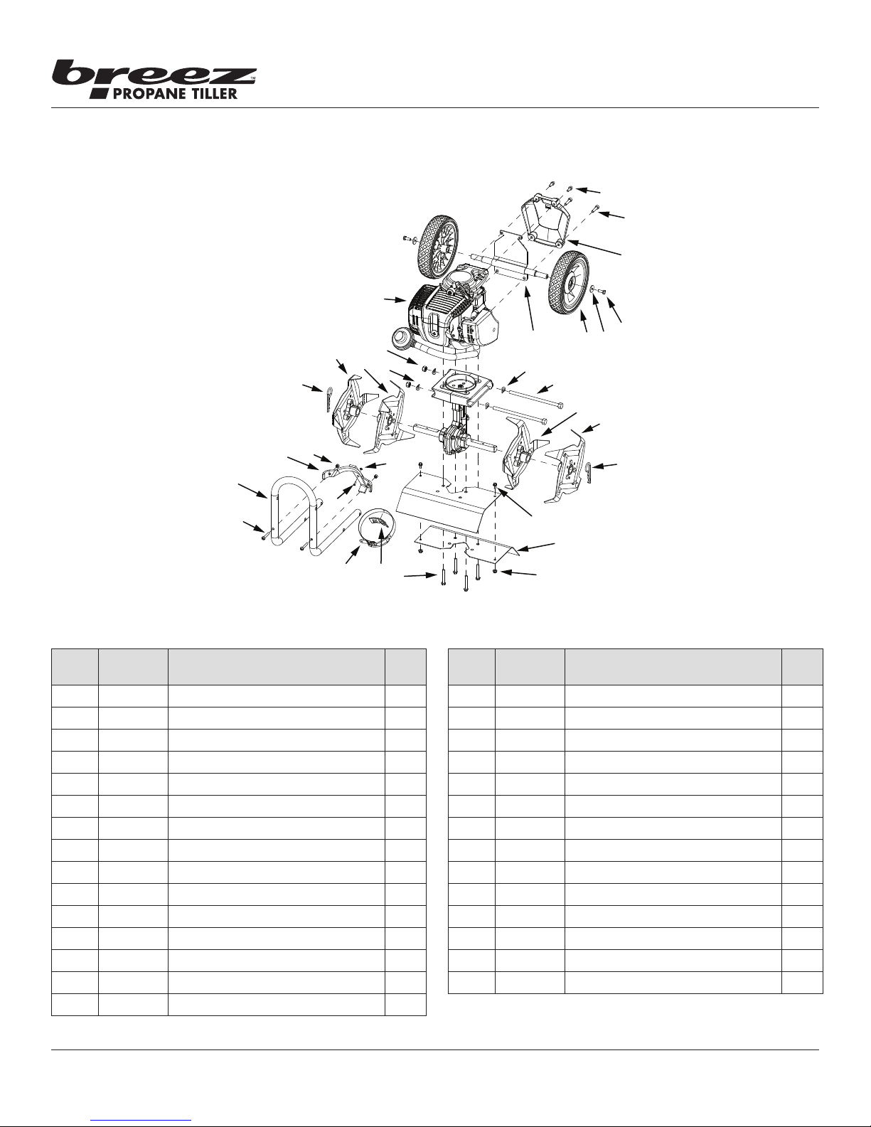
Operator's Manual
2
27
Breez™ R2 Propane Powered Tiller
ILLUSTRATED PARTS BREAKDOWN
13
4
3
1
Hood & Tines Parts Explosion
21
18
20
19
17
6
5
22
17
12
16
11
23
15
28
24
14
26
25
13
8
7
ITEM
NO.
1 18504 BOLT M5 X 0.8 X 30 MM FILLISTER 2
2 21061 LOWER HANDLEBAR 1
3 18504 BRACKET PROPANE TANK MOUNT 1
4 18504 NUT M5 NYLOC 2
5 18504 BOLT M3 X 0.5 X 12 MM PHILIPS 1
6 18504 NUT M3 NYLOC 1
7 18504 PROPANE TANK STRAP 1
8 18504 RUBBER PAD TANK STRAP 1
9 4625 BOLT M6 X 1.0 X 42 FLANGE HEX 4
10 IN58 NUT M5 NYLOC 2
11 21272 TINE SHIELD SIX HOLE ORANGE 2
12 176 BOLT M5 X 0.8 X 10 HEX 2
13 4652 COTTER HAIR PIN 2
14 4604 TINE -D- ASSEMBLY 1
15 4602 TINE -C- ASSEMBLY 1
PART
NO.
DESCRIPTION Q T Y.
9
ITEM
NO.
16 46141 BOLT M8 X 1.25 X 155 MM HEX 2
17 4641 WASHER M8 CURVED 4
18 4601 TINE A ASSEMBLY 1
19 4603 TINE -B- ASSEMBLY 1
20 400023 NUT M8 NYLOC 2
21 21058 ENGINE 40CC 4CYCLE PROPANE 1
22 21562 WHEEL MOUNT PLATE WITH AXLE 1
23 13189 WHEEL 180 X 38 MM GREY 2
24 18581 WASHER M6 X 20 X 2 MM 2
25 17986 BOLT M6 X 1.0 X 16 HEX 2
26 17204 COVER WHEEL MOUNT BLACK 1
27 13222 BOLT M6 X 1.0 X 25 MM SOCKET 2
28 17945 BOLT M5 X 0.8 X 16 MM SOCKET 2
18504 PROPANE TANK BRACKET KIT 1
10
PART
NO.
DESCRIPTION Q T Y.
18
Check for parts online at www.breezpropanetillers.com or call 800-345-6007 M-F 8-5
Page 19
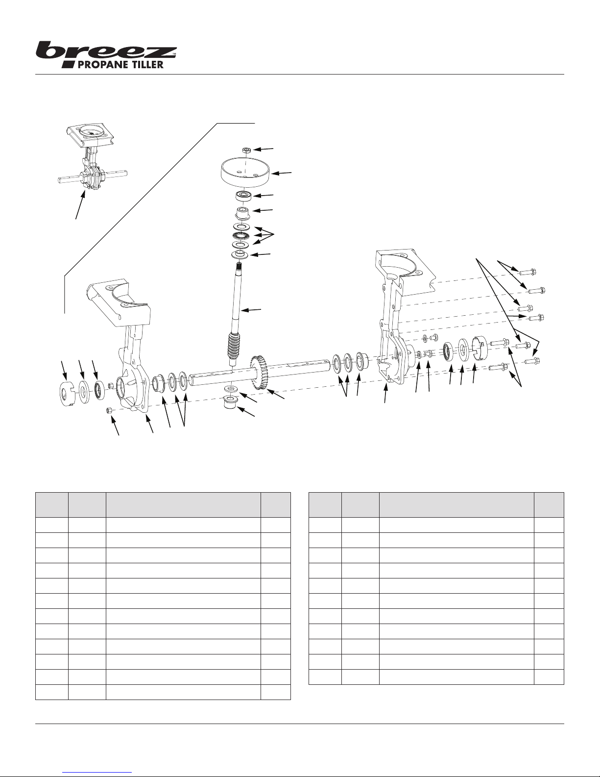
Operator's Manual
Breez™ R2 Propane Powered Tiller
ILLUSTRATED PARTS BREAKDOWN
24
3
2
1
Transmission Parts Explosion
22
21
20
8
19
18
17
15
16
8
6
4
ITEM
NO.
PART
NO.
1 46144 DUST CAP 2
2 4606 WASHER, FIBER 2
3 4646 SEAL, TINE SHAFT 2
4 4650 NUT, FLANGED HEX HD M6 2
5 46136 TRANSMISSION CASTING, LEFT 1
6 4645 BUSHING, TINE SHAFT 2
7 4610 SHIM, TINE SHAFT 4
8 4614 BUSHING, DRIVE SHAFT 2
9 4616 SPACER, BUSHING 1
10 4651 TINE GEAR & SHAFT ASSEMBLY 1
11 46135 TRANSMISSION CASTING, RIGHT 1
W1200117
12 WASHER M6 X 13 X 1.75 MM 2
DESCRIPTION Q TY.
5
7
10
9
ITEM
NO.
13 13447 BOLT M6 X 1.0 X 8 MM PHILIPS 2
14 4649 BOLT M6 X 1.0 X 22 MM HEX FLG 2
15 4647 BOLT M6 X 1.0 X 18 MM HEX FLG 4
16 4648 BOLT M6 X 1.0 X 22 MM HEX FLG 2
17 21953 DRIVE SHAFT TRANSMISSION 1
18 4617 REDUCER, THRUST BEARING 1
19 4615 THRUST BEARING KIT 1
20 4623 BALL BEARING 9MM 1
21 300414 CLUTCH DRUM 1
22 4620 JAM NUT M8 1
23 46138 TRANSMISSION ASSEMBLY 1
6
7
PART
NO.
12
11
DESCRIPTION Q TY.
321
13
14
Check for parts online at www.breezpropanetillers.com or call 800-345-6007 M-F 8-5
19
Page 20
Operator's Manual
Breez™ R2 Propane Powered Tiller
ILLUSTRATED PARTS BREAKDOWN
5
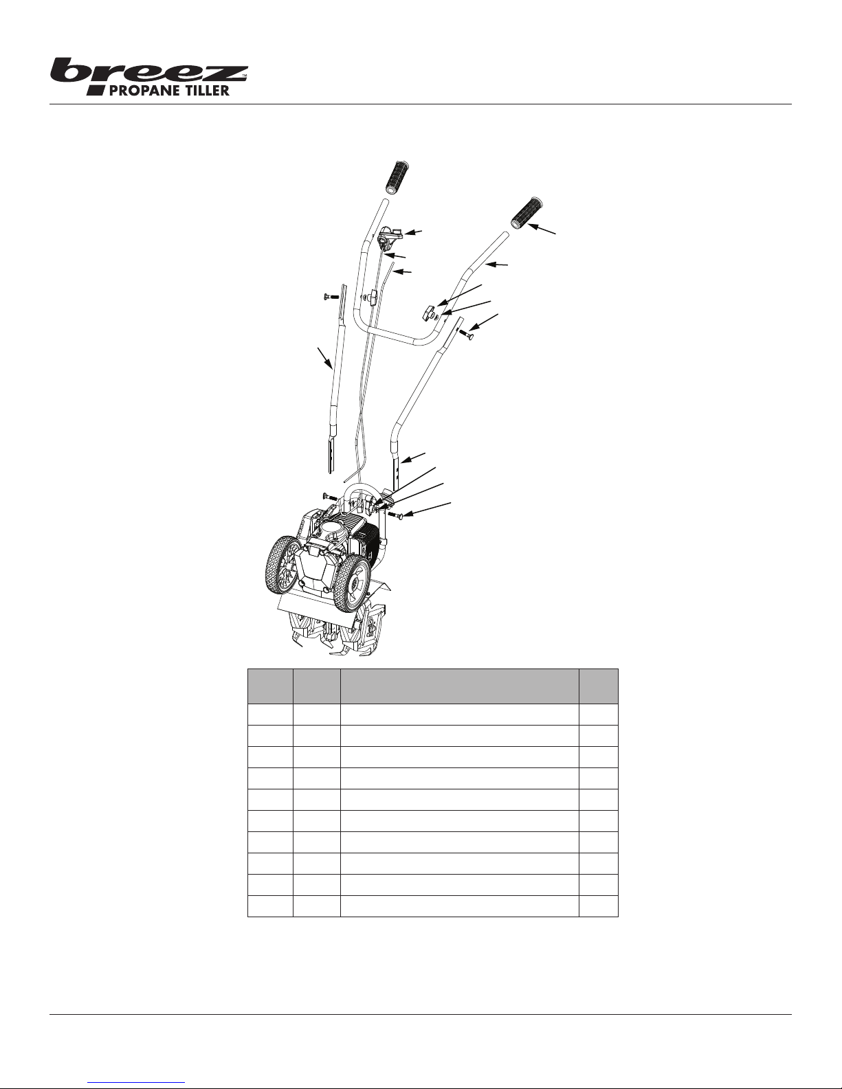
Handlebar Parts Explosion
8
8, 9
10
4
3
2
1
7
6
3
2
1
ITEM
NO.
1 4642 BOLT, HANDLE CLAMP 4
2 4641 WASHER CURVED 4
3 4640 NUT, THANDLE 4
4 11078 MIDDLE HANDLEBAR LEFT 1
5 11077 MIDDLE HANDLEBAR RIGHT 1
6 11045 UPPER HANDLEBAR LOOP 1
7 13309 HANDLEBAR GRIP 2
8 17483 ON/OFF SWITCH HOUSING KIT 1
9 17209 POWER CABLE WITH ON/OFF SWITCH 1
10 14645 THROTTLE CABLE 1
20
PART
Check for parts online at www.breezpropanetillers.com or call 800-345-6007 M-F 8-5
DESCRIPTION QT Y.
NO.
Page 21
Breez™ R2 Propane Powered Tiller
KIT ASSEMBLED
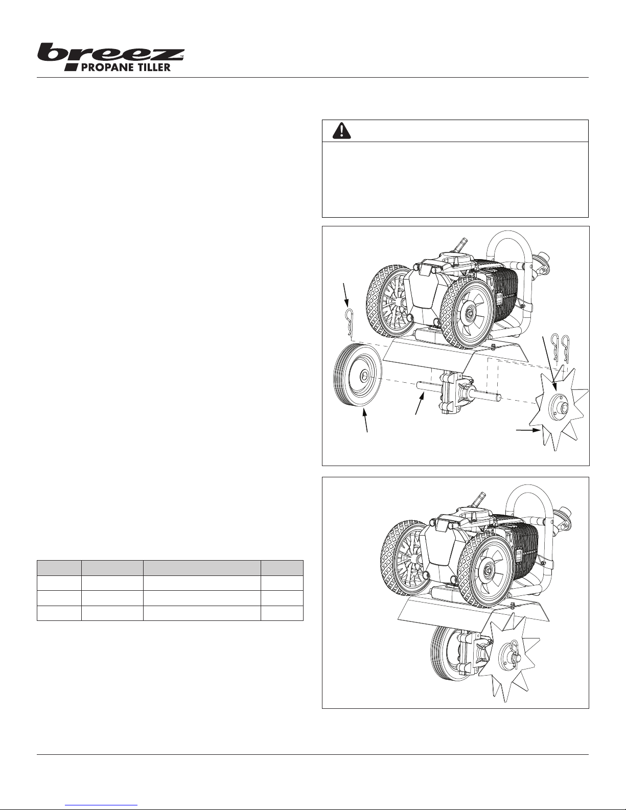
15073 BORDEREDGER KIT INSTALLATION OPTIONAL ACCESSORY
The Border-Edger Kit is a useful tool for making clean cuts in
the lawn along the borders of gardens, ower beds, walkways,
and driveways for a well manicured look. To install the BorderEdger Kit, do the following:
INSTALLATION
1. Make sure the tiller is not running by ipping the ON/OFF
switch to the OFF position.
2. Remove the hairpins from both sides of the tine shaft.
3. Remove the tilling tines from the shaft, remembering which
direction they are facing.
4. Put the tines in a safe place and save the (2) hairpins, they will
be used on the Border-Edger Kit.
5. Slide the border-edger tine onto either side of the tine
shaft. Make sure that the hub collar of the border-edger
tine faces outward, away from the transmission of the tiller.
SEE FIGURE 7
6. Take the (2) hairpins saved in Step 4 and insert them through
the inner and outer holes in the tine shaft on each side of the
border-edger tine to secure the tine blade in place on the
shaft. SEE FIGURE 7
7. Slide the border-edger wheel onto the opposite side of the
tine shaft as far as it will go.
8. Insert the remaining (1) hairpin, that came with the kit,
through the inner hole next to the wheel in the middle of the
tine shaft. SEE FIGURE 7
CAUTION
BE AWARE THAT THE TILLER COULD UNEXPECTEDLY
BOUNCE UPWARD, OR JUMP FORWARD IF THE TINES
STRIKE CONCRETE, PAVEMENT, OR OTHER HARD
SURFACES OR HARD OBSTACLES BURIED UNDER
GROUND.
HAIRPIN
TINE SHAFT
BORDER-EDGER WHEEL
FIGURE 7
BORDER-EDGER
Operator's Manual
HUB
COLLAR
TINE
NOTE: Never use the Border-Edger Kit with the drag stake
installed.
PARTS BREAKDOWN
KEY # PART # DESCRIPTION Q TY.
1 15009 BORDEREDGER TINE 1
2 46131 BORDEREDGER WHEEL 1
3 46134 HAIRPIN 1
Check for parts online at www.breezpropanetillers.com or call 800-345-6007 M-F 8-5
21
Page 22
Breez™ R2 Propane Powered Tiller
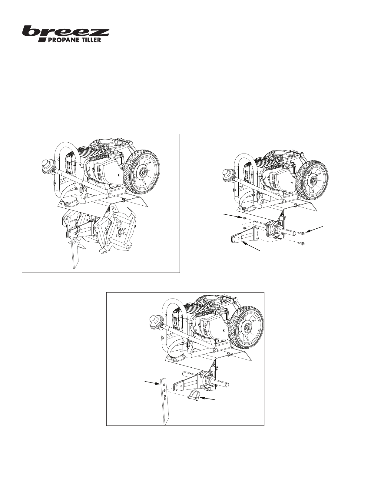
NUT (4650)
BOLT (4649)
DRAG STAKE (4600)
15290 DRAG STAKE BRACKET KIT INSTALLATION OPTIONAL ACCESSORY
The Drag Stake Bracket Kit is very eective for ensuring depth control and straight rows while tilling.
1. Flip the ON/OFF switch to the OFF position. Remove the tilling tines or other working tools.
2. Remove bolts (4649) and nuts (4650) from transmission casting. SEE FIGURE 9
3. Secure bracket (4633) to transmission casting with bolts (4649) and nuts (4650). SEE FIGURE 9
4. Place drag stake (4600) in bracket (4633) and secure at desired depth with lock pin (18039). SEE FIGURE 10
5. Replace tilling tines.
Operator's Manual
FIGURE 8 FIGURE 9
BRACKET (4633)
LOCK PIN (18039)
FIGURE 10
22
Check for parts online at www.breezpropanetillers.com or call 800-345-6007 M-F 8-5
Page 23
Operator's Manual
Breez™ R2 Propane Powered Tiller
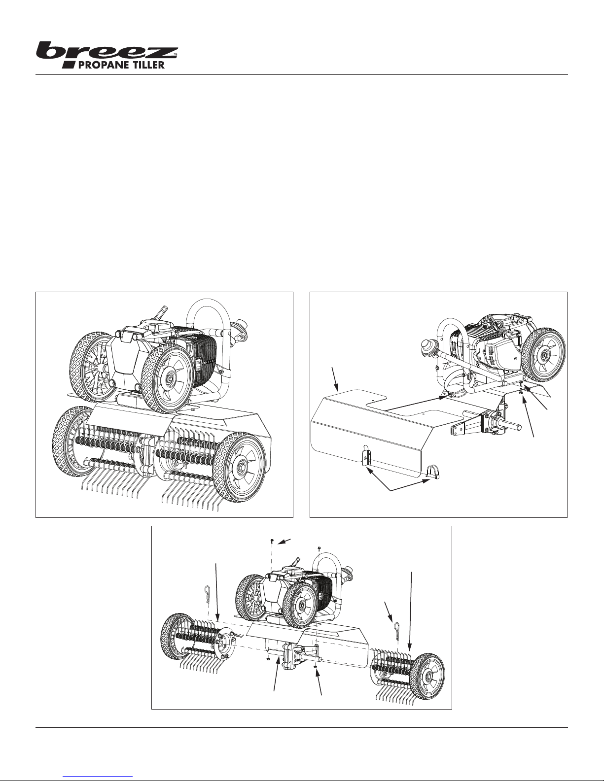
DK43 DETHATCHER KIT INSTALLATION OPTIONAL ACCESSORY
The Dethatcher Kit is very eective for lifting away the excessive matted layers of thatch in your lawn that can prevent moisture,
oxygen and nutrients from penetrating the soil and can harbor disease and insects. Use in Spring, Summer, and Fall to bring life and
color back to your grass lawn.
1. Flip the ON/OFF switch to the OFF position. Remove the tilling tines or other working tools and the drag stake.
2. Slide dethatcher shield over the unit’s tine shield from the rear of the unit and secure using bolts (176) and nuts (400020).
SEE FIGURE 12
3. Secure the lower part of the dethatcher shield to the drag stake mount using the lock pin (18039).
4. Slide the Left and Right Dethatcher Assemblies onto the tine shaft making sure the Right Assembly is installed on the right side
and Left Assembly is installed on the left side as dened from the user’s position. SEE FIGURE 13. Secure dethatcher assemblies
using the hairpins (4652). The hairpins go through the inner holes of the tine shaft.
NOTE: Drag Stake Bracket Kit (15290) is required to use the Dethatcher Kit.
SLIDE
SHIELD
FORWARD
FIGURE 11 FIGURE 12
RIGHT SIDE
DETHATCHER
ASSEMBLY
BOLT (176)
BOLT
(176)
NUT
(400020)
SECURE WITH LOCKPIN
LEFT SIDE
DETHATCHER
ASSEMBLY
HAIRPIN
FIGURE 13
Check for parts online at www.breezpropanetillers.com or call 800-345-6007 M-F 8-5
TINE SHAFT
NUT (400020)
23
Page 24

NOTES
Operator's Manual
Breez™ R2 Propane Powered Tiller
24
Check for parts online at www.breezpropanetillers.com or call 800-345-6007 M-F 8-5
Page 25
Operator's Manual
Breez™ R2 Propane Powered Tiller
WARRANTY TERMS AND CONDITIONS
PRODUCT WARRANTY: 1YEAR LIMITED WARRANTY
Ardisam, Inc. (Ardisam) warrants the product(s) under a one-year limited warranty to be free from defects in the material or
workmanship or both for a period not exceeding twelve consecutive months from the date of original purchase by the rst retail
consumer or rst commercial end user. “Consumer use“ means personal recreational use by a retail consumer. “Commercial use“
or “commercial application“ means all other uses, including use for commercial, income producing or rental purposes. Once
a product has experienced commercial use, it shall thereafter be considered as a commercial use product for the purpose of
this warranty. This warranty applies to the original owner that provides a proof of purchase. The warranty is not transferable.
The warranty period begins on the date of purchase by the rst retail consumer or commercial end user, and continues for
the twelve month consecutive period thereafter. Any unit used in a commercial application is covered for a period of 90 days
after purchase by the rst commercial end user. For the warranty to be valid, the product must be registered online, or the
warranty card must be lled out and received by Ardisam, within 30 days of purchase. Ardisam shall not be obligated to ship
any repair or replacement product to any location outside of the United States of America or Canada.*
ENGINE WARRANTY: 2-YEAR LIMITED EMISSIONS CONTROL WARRANTY
(SEE EXPLANATION OF EMISSIONS CONTROL WARRANTY STATEMENT FOR DETAILS)
Ardisam warrants the Viper® engine(s) under a two-year limited emissions control warranty to be free from defects in the
materials or workmanship or both for the service life of the product not to exceed twenty-four consecutive months from the
date of purchase for consumer applications. As a Viper® small engine owner, you are responsible to perform periodic maintenance as specied in the product’s operator’s manual and/or engine manual. The warranty period begins on the date of
purchase by the rst retail consumer or commercial end user, and continues for the period of time stated above.*
For replacement parts, phone 800-345-6007.
*This warranty policy applies only to products which have not been subjected to negligent use, misuse, uses other than
those indicated in the product’s operator’s manual, alteration, accident, use of unauthorized parts, failure to perform periodic
maintenance as specied in product’s operator’s manual, normal wear and tear, use of unauthorized parts or repairs performed
at unauthorized service centers. There is no other expressed warranty. Implied warranties, including those of merchantability
and tness for a particular purpose, are limited to one year from purchase, or to the extent permitted by law. All other implied
warranties are excluded. Liability for incidental or consequential damages are excluded to the extent exclusion is permitted by
law. Ardisam does not assume, and does not authorize any other person to assume for Ardisam, any liability in connection with
the sale of Ardisam products. To be at “No Charge,” warranty work must be sent directly to and performed by Ardisam or
an Ardisam Authorized Warranty Service Facility. To obtain warranty service and/or replacement instructions, contact the
Ardisam Customer Service Department at 800-345-6007. If you choose to ship your product to Ardisam for warranty repair,
you must rst have prior approval from Ardisam by calling the Ardisam Customer Service Department for a return material
authorization number (RMA#). Under these circumstances, all items must be shipped prepaid. For Viper® engine warranty
repairs, Ardisam will cover the cost of shipping only for purchasers located more than 100 miles from an Ardisam Authorized
Warranty Service Facility if it is determined that warranted repair is indeed necessary. Ardisam will at no charge, repair or
replace, at the discretion of Ardisam, any defective part which satises all conditions stated above. Ardisam retains the right
to change models, specications and price without notice. Ardisam shall not be obligated to ship any repair or replacement
product to any location outside of the United States of America or Canada.
Check for parts online at www.breezpropanetillers.com or call 800-345-6007 M-F 8-5
17645-REV1
25
Page 26

FEDERAL EMISSIONS CONTROL WARRANTY STATEMENT
Operator's Manual
Breez™ R2 Propane Powered Tiller
YOUR WARRANTY RIGHTS AND OBLIGATIONS
The United States Environmental Protection Agency (EPA), together
with Ardisam, Inc. (Ardisam), are pleased to explain the Emission
Control System Warranty on your small o-road engine (SORE). New
small o-road engines must be designed, built and equipped to meet
stringent anti-smog standards the federal government. Ardisam will
warrant the emission control system on your engine for the periods of
time listed below provided there has been no abuse, neglect, modication or improper maintenance of your engine.
The emission control system includes all components whose failure
would increase the emissions of any regulated pollutant. These
components are listed in the emission-related parts list located in a
subsequent section of this emissions warranty statement. Ardisam
will repair your engine at no cost to you for diagnosis, replacement
parts and labor, should a warrantable condition occur.
MANUFACTURER’S WARRANTY COVERAGE:
The emission control system is warranted for two years. If, during such
warranty period, any emission-related part on your engine is found to
be defective in materials or workmanship, repairs or replacement will
be performed by an Ardisam Authorized Warranty Service Facility.
PURCHASER’S/OWNER’S WARRANTY RESPONSIBILITIES:
As the SORE purchaser/owner, you are responsible for the completion of all required maintenance as listed in your factory supplied
Manual(s). For warranty purposes, Ardisam recommends that you
retain all receipts covering maintenance on your SORE. However,
Ardisam cannot deny warranty solely because of the lack of receipts
or for your failure to ensure the completion of all scheduled maintenance.
As the SORE purchaser/owner, you should, however, be aware that
Ardisam may deny any and/or all warranty coverage or responsibility
if your SORE or a part/component thereof, has failed due to abuse,
neglect, improper maintenance or modications, or the use of counterfeit and/or “grey market” parts not made, supplied or approved by
Ardisam.
You are responsible for presenting your SORE to an Ardisam Authorized Warranty Service Facility as soon as a problem occurs. The warranty repairs should be completed in a reasonable amount of time,
not to exceed 30 days.
Warranty service can be arranged by contacting either your selling
dealer or an Ardisam Authorized Warranty Service Facility. To locate
the Ardisam Authorized Warranty Service Facility nearest you, call our
free number:
800-345-6007
IMPORTANT NOTE: This warranty statement explains your rights and
obligations under the Emission Control System Warranty (ECS Warranty), which is provided to you by Ardisam pursuant to federal law.
See also the Ardisam “Product Warranty” (non-emission warranties),
which is enclosed herewith on a separate sheet or located in additional materials accompanying this product. The ECS Warranty applies
only to the emission control system of your new engine. If there is
any conict in terms between the ECS Warranty and the Ardisam
Warranty, the ECS Warranty shall apply except in circumstances where
the Ardisam Warranty may provide a longer warranty period. Both the
ECS Warranty and the Ardisam Warranty describe important rights
and obligations with respect to your new engine.
Warranty service can be performed only by an Ardisam Authorized
Warranty Service Facility. When requesting warranty service, evidence must be presented showing the date of the sale to the original
purchaser/owner. Ardisam will not be responsible for any and/or all
damages or losses incurred while the engine is being transported/
shipped for inspection or warranty repairs.
IF YOU HAVE ANY QUESTIONS REGARDING YOUR WARRANTY RIGHTS
AND RESPONSIBILITIES, YOU SHOULD CONTACT ARDISAM AT THE
FOLLOWING ADDRESS:
Ardisam, Inc.
1160 8th Avenue; P.O. Box 666
Cumberland, Wisconsin 54829
800-345-6007 · Fax (715) 822-4180
E-mail: [email protected]
II. EMISSION CONTROL SYSTEM WARRANTY
Emission Control System Warranty (ECS Warranty) for equipment using small o-road engines:
(a) Applicability: This warranty shall apply to equipment that uses
small o-road engines. The ECS Warranty Period shall begin on the
date the new engine or equipment is purchased by/delivered to its
original, end-use purchaser/owner and shall continue for 24 consecutive months thereafter.
(b) General Emissions Warranty Coverage: Ardisam warrants to the
original, end-use purchaser/owner of the new engine or equipment
and to each subsequent purchaser/owner that each of its engines is...
(1) Designed, built and equipped so as to conform with all applicable regulations adopted by the EPA pursuant to their respective
authority, and
(2) Free from defects in materials and workmanship which, at
any time during the ECS Warranty Period, may cause a warranted
emissions-related part to fail to be identical in all material respects
to the part as described in the engine manufacturer’s application
for certication.
The ECS Warranty only pertains to emissions-related parts on your
engine, as follows:
(1) Any warranted, emissions-related parts that are not scheduled
for replacement as required maintenance in the Maintenance
Schedule (located in the section of the Manual(s) pertaining to
maintenance) shall be warranted for the ECS Warranty Period. If any
such part fails during the ECS Warranty Period, it shall be repaired
or replaced by Ardisam according to Subsection (4) below. Any
such part repaired or replaced under the ECS Warranty shall be
warranted for the remainder of the ECS Warranty Period.
(2) Any warranted, emissions-related part that is scheduled only
for regular inspection as specied in the Maintenance Schedule
(located in the section of the Manual(s) pertaining to maintenance)
26
Check for parts online at www.breezpropanetillers.com or call 800-345-6007 M-F 8-5
Page 27

Operator's Manual
Breez™ R2 Propane Powered Tiller
shall be warranted for the ECS Warranty Period. A statement in such
written instructions to the eect of “repair or replace as necessary”
shall not reduce the ECS Warranty Period. Any such part repaired or
replaced under the ECS Warranty shall be warranted for the remainder of the ECS Warranty Period.
(3) Any warranted, emissions-related part that is scheduled for replacement as required maintenance in the Maintenance Schedule
(located in the section of the Manual(s) pertaining to maintenance)
shall be warranted for the period of time prior to the rst scheduled
replacement point for that part. If the part fails prior to the rst
scheduled replacement, the part shall be repaired or replaced by
Ardisam according to Subsection (4) below. Any such emissionsrelated part repaired or replaced under the ECS Warranty shall be
warranted for the remainder of the ECS Warranty Period prior to the
rst scheduled replacement point for such emissions-related part.
(4) Repair or replacement of any warranted, emissions-related part
under this ECS Warranty shall be performed at no charge to the
owner at an Ardisam Authorized Warranty Service Facility.
(5) When the engine is inspected by an Ardisam Authorized Warranty Service Facility, the owner shall not be held responsible for
diagnostic costs if the repair is deemed warrantable.
(6) Ardisam shall be liable for damages to other original engine
components or approved modications proximately caused by a
failure under warranty of any emission-related part covered by the
ECS Warranty.
(7) Throughout the ECS Warranty Period, Ardisam shall maintain a
supply of warranted emission-related parts sucient to meet the
expected demand for such emission-related parts.
(8) Any Ardisam authorized and approved emission-related
replacement part may be used in the performance of any ECS Warranty maintenance or repairs and will be provided without charge
to the purchaser/owner. Such use shall not reduce Ardisam’s ECS
Warranty obligations.
(9) Unapproved, add-on, modied, counterfeit and/or “grey market”
parts may not be used to modify or repair an Ardisam engine. Such
use voids this ECS Warranty and shall be sucient grounds for
disallowing an ECS Warranty claim. Ardisam shall not be held liable
hereunder for failures of any warranted parts of an Ardisam engine
caused by the use of such an unapproved, add-on, modied, counterfeit and/or “grey market” part.
(2) Air Induction System
(i) Controlled hot air intake system.
(ii) Intake manifold.
(iii) Air lter.
(3) Ignition System
(i) Spark Plugs.
(ii) Magneto or electronic ignition system.
(iii) Spark advance/retard system.
(4) Exhaust Gas Recirculation (EGR) System
(i) EGR valve body, and carburetor spacer if applicable.
(ii) EGR rate feedback and control system.
(5) Air Injection System
(i) Air pump or pulse valve.
(ii) Valves aecting distribution of ow.
(iii) Distribution manifold.
(6) Catalyst or Thermal Reactor System
(i) Catalytic converter.
(ii) Thermal reactor.
(iii) Exhaust manifold.
(7) Particulate Controls
(i) Traps, lters, precipitators, and any other device used to cap-
ture particulate emissions.
(8) Miscellaneous Items Used in Above Systems
(i) Electronic controls.
(ii) Vacuum, temperature, and time sensitive valves and switch-
es.
(iii) Hoses, belts, connectors, and assemblies.
EMISSION-RELATED PARTS INCLUDE THE FOLLOWING
(IF EQUIPPED):
(1) Fuel Metering System
(i) Carburetor and internal parts (and/or pressure regulator or
fuel injection system).
(ii) Air/fuel ratio feedback and control system.
(iii) Cold start enrichment system.
(iv) Fuel Tank.
Check for parts online at www.breezpropanetillers.com or call 800-345-6007 M-F 8-5
27
Page 28

All weights, specications and features are approximate and are subject to change without notice. Due to continuous product
improvements, product images may not be exact. Items used for props not included. Some assembly may be required.
Check for parts online at www.breezpropanetillers.com or call 800-345-6007 M-F 8-5
Breez™, Division of Ardisam, Inc.
1160 8th Avenue, PO Box 666
Cumberland, WI 54829
800-345-6007 | Fax 715-822-2223
E-mail: [email protected]
 Loading...