

Breckwell SWC31 Owner's Operation And Instruction Manual
Owner’s Operation and Instruction Manual
SAFETY NOTICE:
If this heater is not properly installed, a house re may
result. For your safety, follow the installation instructions. Never use make-shi compromises during the
installation of this heater. Contact local building or
re o cials about permits, restrictions and installation requirements in your area.
MODEL: SWC31
CONFORMS TO UL STD 1482 and CERTIFIED TO ULC STD S627
US ENVIRONMENTAL PROTECTION AGENCY PHASE II CERTIFIED WOODSTOVE
WASHINGTON STATE APPROVED
MOBILE HOME APPROVED (U.S. ONLY)
CAUTION!
Please read this entire manual before you install or
use your new room heater. Failure to follow instruc-
tions may result in property damage, bodily injury,
or even death.
Improper Installation Could Void
SAFETY NOTICE:
If this heater is not properly installed, a house re may
result. For your safety, follow the installation instructions. Never use make-shi compromises during the
installation of this heater. Contact local building or
re o cials about permits, restrictions and installation requirements in your area.
Your Warranty!
SAVE THESE INSTRUCTIONS
THIS MANUAL WILL HELP YOU TO OBTAIN EFFICIENT, DEPENDABLE SERVICE FROM THE HEATER, AND ENABLE YOU TO OR-
DER REPAIR PARTS CORRECTLY. KEEP IN A SAFE PLACE FOR FUTURE REFERENCE.
French version is available for download from the Breckwell website: http://www.breckwell.com/
La version française est disponible pour téléchargement à partir du site Breckwell: http://www.breckwell.com/
United States Stove Company
227 Industrial Park Road
P.O. Box 151
South Pittsburg, TN 37380
852246 B
CONGRATULATIONS!
You’ve purchased a heater from North America’s oldest manufacturer of wood burning products.
By heating with wood you’re helping to CONSERVE ENERGY!
Wood is our only Renewable Energy Resource. Please do your part to preserve our wood supply. Plant at least one tree each year.
Future generations will thank you.
e instructions pertaining to the installation of your wood stove comply with UL-1482 and ULC-S627 standards.
Combustible : Wood
Colors : Metallic Black
Flue Pipe Diameter : 6” (152.5mm)
Flue Pipe Type: (Standard Single Wall or Double Wall): Black or Blued Steel 2100°F (650°C)
Minimum Chimney Hieght : 12’ (3.7m)
Maximum Log Length : 21” (533.5mm)
Dimensions
Overall :
Depth x Width x Height :
Combustion Chamber :
Width x Depth :
Volu m e :
Cubic Feet:
Door Opening : Width x Height: 16” x 8” (406.5mm x 203mm)
Pyroceramic Glass Door : (Viewing) Width x Height: 13
22” x 30” x 31.25” (559mm x 762mm x 794mm)
3
”
/
22
x 12” (578mm x 305mm)
4
1.86 ³ (.0527m³)
13
3
”
”
/
16
/
8
x 8
(351mm x 213mm)
OPTIONAL ACCESSORIES
DESCRIPTION PART #
Outside Air Intake Kit 50FAK
CAUTIONS:
• HOT WHILE IN OPERATION. KEEP CHILDREN, CLOTHING AND FURNITURE AWAY.
CONTACT MAY CAUSE SKIN BURNS.
• DO NOT USE CHEMICALS OR FLUIDS TO IGNITE THE FIRE.
• DO NOT LEAVE THE STOVE UNATTENDED WHEN THE DOOR IS SLIGHTLY OPENED.
• DO NOT BURN GARBAGE, FLAMMABLE FLUID SUCH AS GASOLINE, NAPHTHA OR
MOTOR OIL.
• DO NOT CONNECT TO ANY AIR DISTRIBUTION DUCT OR SYSTEM.
• ALWAYS CLOSE THE DOOR AFTER THE IGNITION.
2 Ussc
Tools and Materials Needed For Installation
You will need a drill with a 1/8” bit to install sheet metal screws into connector pipe. A 5/16” socket/wrench or screw driver to install
pedestal trim, room air de ector, and blower assembly described below. A 1/2” socket/wrench to install ue collar. A non-combustible
oor protector as speci ed in this manual. All chimney and chimney connector components required for your particular chimney
installation. For mobile homes, see page 13.
Assembly
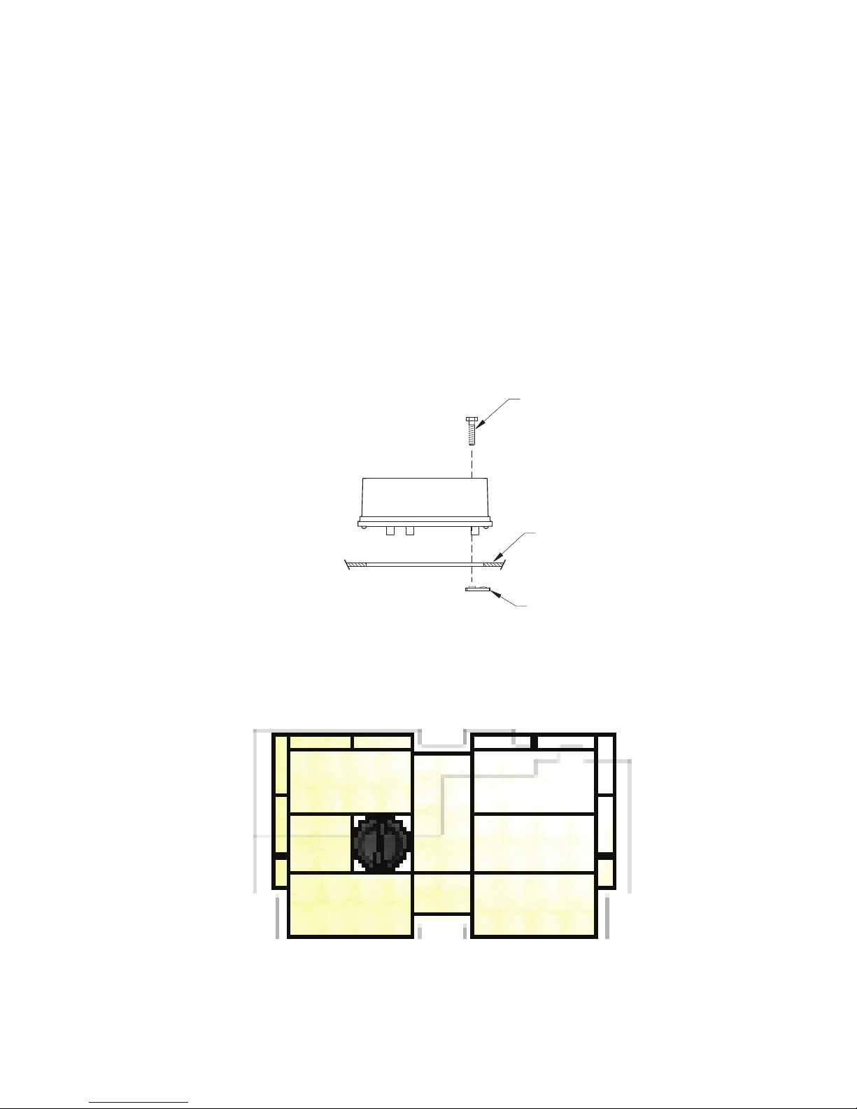
Flue Collar Assembly:
1. Mount the ue collar to the top of the unit as shown using the (3)
tabs
provided in the parts box.
Room Air De ector Assembly:
1. Locate the Room Air De ector. Using the three(3) 1/2 Tek Screws provided, mount the de ector to the unit as
shown in the diagram.
Firebrick Con guration:
1. Replace the Firebrick as shown in the illustration below.
5/16-18 x 1-1/2 bolts, (3) washers, and (3) weld
Side view of fl ue collar
mount to heater top
Brick Confi guration
5/16-18 x 1-1/2
BOLT
HEATER
TOP
WELD
TAB
Ussc 3
ASSEMBLY INSTRUCTIONS
Blower Assembly
THE BLOWER ASSEMBLY MUST BE DISCONNECTED FROM THE SOURCE OF ELECTRICAL SUPPLY BEFORE
ATTEMPTING THE INSTALLATION.
THE BLOWER ASSEMBLY IS INTENDED FOR USE ONLY WITH A STOVE THAT IS MARKED TO INDICATE SUCH USE.
DO NOT ROUTE THE SUPPLY CORD NEAR OR ACROSS HOT SURFACES!
Step 1.
Fix the assembly to the back of the stove with the four screws provided.
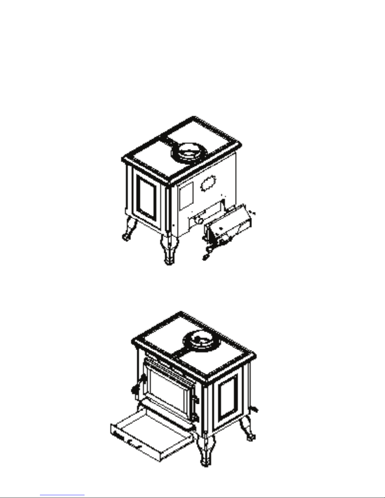
Ash Pan Assembly
Remove ash pan from fi rebox. Under the fi rebox, there
are two brackets; Slide the ash pan into these brackets.
4 Ussc

INSTALLATION
SAFETY NOTICE
• IF THIS STOVE IS NOT PROPERLY INSTALLED, A HOUSE FIRE MAY RESULT. TO REDUCE THE
RISK OF FIRE, FOLLOW THE INSTALLATION INSTRUCTIONS.
• CONSULT YOUR MUNICIPAL BUILDING DEPARTMENT OR FIRE OFFICIALS ABOUT PERMITS,
RESTRICTIONS AND INSTALLATIONS REQUIREMENTS IN YOUR AREA.
• USE SMOKE DETECTORS IN THE ROOM WHERE YOUR STOVE IS INSTALLED.
• KEEP FURNITURE AND DRAPES WELL AWAY FROM THE STOVE.
• NEVER USE GASOLINE, GASOLINE-TYPE LANTERN FUEL, KEROSENE, CHARCOAL LIGHTER
FLUID, OR SIMILAR LIQUIDS TO START OR “FRESHEN UP” A FIRE IN THIS HEATER. KEEP ALL
SUCH LIQUIDS WELL AWAY FROM THE HEATER WHILE IT IS IN USE.
• IN THE EVENT OF A CHIMNEY FIRE, PUSH THE AIR CONTROL FULL CLOSED TO DEPRIVE
THE FIRE OF OXYGEN. CALL THE FIRE DEPARTMENT.
• DO NOT CONNECT TO ANY AIR DISTRIBUTION DUCT OR SYSTEM.
• A SOURCE OF FRESH AIR INTO THE ROOM OR SPACE HEATED SHALL BE PROVIDED WHEN
REQUIRED.
POSITIONING THE STOVE
It is very important to position the wood stove as close as possible to the chimney, and in an area that will favor
the most e cient heat distribution possible throughout the house. e stove must therefore be installed in the
room where the most time is spent, and in the most spacious room possible. Recall that wood stoves produce
radiating heat, the heat we feel when we are close to a wood stove. A wood stove also functions by convection,
that is through the displacement of hot air accelerated upwards and its replacement with cooler air. If necessary,
the hot air distribution from the stove may be facilitated by the installation of a blower.
e wood stove must not be hooked up to a hot air distribution system since an excessive accumulation of heat
may occur.
A wood stove must never be installed in a hallway or near a staircase, since it may block the way in case of re
or fail to respect required clearances.
Ussc 5
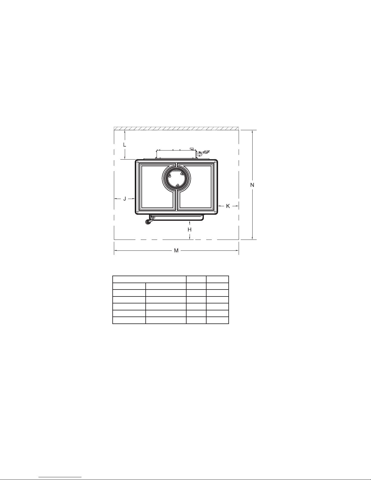
FLOOR PROTECTOR
Your wood stove should be placed on a 1 inch, non-combustible surface with a k factor of 0.84. For multiple layers,
add R-values of each layer to determine the overall R-value. e R value for the required board is 1.03. If there
is a horizontal section of chimney connector, the oor protector should go under it and 2 inches beyond each
side
To calculate R-Values for alternative methods, see ALTERNATE FLOOR PROTECTOR CALCULATIONS
section in this manual.
e oor protector should exceed the stove as follows:
Dimension Inch mm
H Front 16 635
J** Left 6 153
K** Right 6 153
L** Back 1 25
M Total Width 46 1169
N Total Length 53.5 1359
* Canadian installations require 18” (457mm)
** Canadian installations require 8” (203mm)
6 Ussc
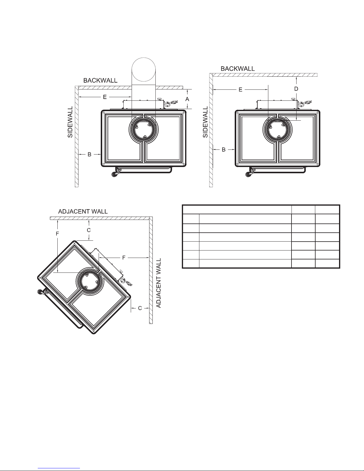
CLEARANCES TO COMBUSTIBLES
It is of utmost importance that the clearances to combustible materials be strictly adhered to during installation of the
stove. Refer to the tables below :
Dimension Inch mm
A Backwall to Stove 16 406
B Sidewall to Stove 18 457
C Wall to corner (Angled Installation) 12 305
D Backwall to Flue 21.5 546
E Sidewall to Flue 30 762
F Wall to Flue (Angled Installation) 24 610
• Floor to ceiling height must be at least 7’ (2.13m) in all cases.
• Do not place any combustible material within 4’ (1.2m) of the front of the unit.
• e clearance between the ue pipe and a wall are valid only for vertical walls and for vertical ue pipe.
• e chimney connector must not pass through an attic or roof space, closet or similar concealed space, a oor, or a
ceiling.
• For Canadian installations, where passage through a wall, or partition of combustible construction is desired, the installation must conform to CAN/CSA-B365.
• A ue pipe crossing a combustible wall must have a minimum clearance of 18” (457.2mm).
• To reduce ue clearances from combustible materials, contact your local safety department.
Ussc 7

CHIMNEY CONNECTOR (STOVE PIPE)
Your chimney connector and chimney must have the same diameter as the stove outlet (6”). If this is not the
case, we recommend you contact your dealer in order to insure there will be no problem with the dra .
e stove pipe must be made of aluminized or cold roll steel with a minimum thickness of 0.021” or 0.53 mm.
It is strictly forbidden to use galvanized steel.
Your smoke pipe should be assembled in such a way that the male section (crimped end) of the pipe faces down.
Attach each of the sections to one another with three equidistant metal screws.
e pipe must be short and straight. All sections installed horizontally must slope at least 1/4 inch per foot,
with the upper end of the section toward the chimney. Any installation with a horizontal run of chimney pipe
must conform to NFPA 211.
latest edition of the NFPA Standard 211.
To insure a good dra , the total length of the coupling pipe should never exceed 8’ to 10’ (2.4m to 3.04 m).
(Except for cases of vertical installation, cathedral-roof style where the smoke exhaust system can be much
longer and connected without problem to the chimney at the ceiling of the room).
ere should never be more than two 90 degrees elbows in the smoke exhaust system.
Installation of a “barometric dra stabilizer” ( replace register) on a smoke exhaust system is prohibited.
Furthermore, installation of a dra damper is not recommended. Indeed, with a controlled combustion wood
stove, the dra is regulated upon intake of the combustion air in the stove and not at the exhaust.
You may contact NFPA (National Fire Protection Association) and request the
8 Ussc
 Loading...