

Breckwell SWC21 Owner's Operation And Instruction Manual
MODEL: SWC21
Please read this entire manual before you install or use
your new room heater. Failure to follow instructions may
result in property damage, bodily injury, or even death.
Improper Installation Could Void Your Warranty!
If this heater is not properly installed, a house fi re may result.
For your safety, follow the installation instructions. Never
use make-shift compromises during the installation of this
heater. Contact local building or fi re offi cials about permits,
restrictions and installation requirements in your area.
CAUTION!
SAFETY NOTICE:
CONFORMS TO UL 1482, AND CERTIFIED TO ULC-S627
US ENVIRONMENTAL PROTECTION AGENCY PHASE II CERTIFIED WOODSTOVE
ALSO SUITABLE FOR MOBILE HOME INSTALLATION.
French version is available for download from the breckwell website: http://www.breckwell.com/
La version française est disponible pour téléchargement à partir du site breckwell: http://www.breckwell.com/
THIS MANUAL WILL HELP YOU TO OBTAIN EFFICIENT, DEPENDABLE SERVICE FROM THE HEATER, AND ENABLE
YOU TO ORDER REPAIR PARTS CORRECTLY. KEEP IN A SAFE PLACE FOR FUTURE REFERENCE.
Breckwell
227 Industrial Park Rd.
South Pittsburg, TN 37380
Approved for installation in the U.S.A.
SAVE THESE INSTRUCTIONS
852211 A
1.0 SPECIFICATIONS
CONGRATULATIONS!
You’ve purchased a heater from North America’s oldest manufacturer of wood burning products.
By heating with wood you’re helping to CONSERVE ENERGY!
Wood is our only Renewable Energy Resource. Please do your part to preserve our wood supply. Plant at least one tree each year.
Future generations will thank you.
Combustible : Wood
Colors : Metallic Black
Flue Pipe Diameter : 6” (153cm)
Flue Pipe Type: (Standard Single Wall or Double Wall): Black or Blued Steel 2100°F (650°C)
Minimum Chimney Height : 12’ (3.7m)
Maximum Log Length : 18” (457mm)
Electrical 115V, 60Hz, 1.5A
Dimensions
Overall : (without Pedestal, Legs or Facade)
Depth x Width x Height :
Combustion Chamber :
Width x Depth :
Volume :
Cubic Feet:
Door Opening : Width x Height: 17” x 8.6” (4.32mm x 2.18mm)
Pyroceramic Glass Door : (Viewing) Width x Height: 16.5” x 10” (419mm x 254mm)
Weight (lbs): 450 lbs
31” x 33” x 25” (787mm x 838mm x 635mm)
18.3” x 11.5” (465mm x 293mm)
1.4 cubic feet
CAUTIONS:
HOT WHILE IN OPERATION. KEEP CHILDREN, CLOTHING AND FURNITURE AWAY. CONTACT
MAY CAUSE SKIN BURNS.
DO NOT USE CHEMICALS OR FLUIDS TO IGNITE THE FIRE.
DO NOT LEAVE THE STOVE UNATTENDED WHEN THE DOOR IS SLIGHTLY OPENED.
DO NOT BURN GARBAGE, FLAMMABLE FLUID SUCH AS GASOLINE, NAPHTHA OR MOTOR OIL.
DO NOT CONNECT TO OR USE IN CONJUNCTION WITH ANY AIR DISTRIBUTION DUCTWORK
UNLESS SPECIFICALLY APPROVED FOR SUCH INSTALLATIONS.
ALWAYS CLOSE THE DOOR AFTER THE IGNITION.
CONSULT YOUR MUNICIPAL BUILDING DEPARTMENT OR FIRE OFFICIALS ABOUT PERMITS,
RESTRICTIONS AND INSTALLATIONS REQUIREMENTS IN YOUR AREA.
2
2.0 PRE-ASSEMBLY
2.1 UNPACK AND INSPECT
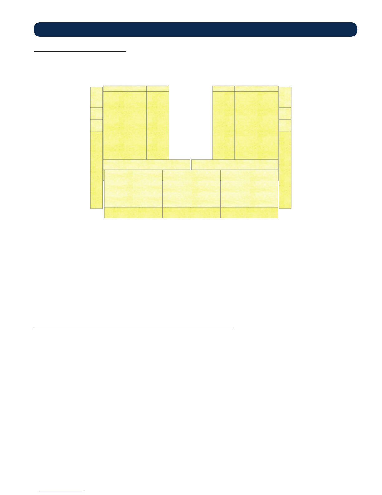
Remove the packing from the appliance and inspect for any damage. Ensure that the bricks are positioned correctly and not broken
(see illustration for proper brick arrangement). Make sure that the baffl e board, above the air tubes, is in place and undamaged. DO
NOT remove the baffl e board.
BRICK CONFIGURATION
2.2 TOOLS AND MATERIALS NEEDED FOR INSTALLATION
A 7/16” socket wrench
A 5/16” socket (Best if using a power drill and a socket bit)
A pair of pliers or channel-locks
A power drill with an 1/8” drill bit to install sheet metal screws into connector pipe.
Sheet metal screws
A non-combustible fl oor protector as specifi ed in this manual
All chimney and chimney connector components required for your particular venting installation.
3

3.0 ASSEMBLY
3.1 ASSEMBLY INSTRUCTIONS
Read and follow the directions in this manual to ensure proper assembly, installation and operation of your new wood heater.
Caution! The appliance is very heavy.
The assistance from a second person is strongly suggested. Please use proper lifting technic when positioning the appliance for
assembly and installation. Several methods may be used to attach the legs and pedestal to the appliance. The safest method is to roll
the appliance on its back. When using this method, you should fi rst remove the fi rebrick from the unit so as to reduce weight and
possible breakage. It will be required to raise the bottom of the unit up to attach two of the legs. It is recommended that you use
cardboard or other means of padding to protect the fi nish on your new stove.
3.2 FREESTANDING LEG ASSEMBLY
1) Unpack the stove and ensure all components are present:
2) Position the unit for assembly.
3) Make sure that the fi re brick is in place and undamaged. DO NOT remove the fi re brick.
4
4.0 INSTALLATION
a
/
a
o
at
éa
e
g
SAFETY NOTICE
IF THIS STOVE IS NOT PROPERLY INSTALLED, A HOUSE FIRE MAY RESULT. TO REDUCE THE RISK OF
FIRE, FOLLOW THE INSTALLATION INSTRUCTIONS.
CONSULT YOUR MUNICIPAL BUILDING DEPARTMENT OR FIRE OFFICIALS ABOUT PERMITS,
RESTRICTIONS AND INSTALLATIONS REQUIREMENTS IN YOUR AREA.
USE SMOKE DETECTORS IN THE ROOM WHERE YOUR STOVE IS INSTALLED.
SMOKE EXPELLED FROM THE UNIT, BY EITHER PAINT CURING, OPENING THE FUEL LOADING DOOR,
OR A NEGATIVE PRESSURE INSIDE THE HOME, COULD TRIGGER THE SMOKE DETECTORS. MOUNT
SMOKE DETECTORS AT LEAST 10’ FROM STOVE
NEVER USE GASOLINE, GASOLINE-TYPE LANTERN FUEL, KEROSENE, CHARCOAL LIGHTER FLUID,
OR SIMILAR LIQUIDS TO START OR “FRESHEN UP” A FIRE IN THIS HEATER. KEEP ALL SUCH LIQUIDS
WELL AWAY FROM THE HEATER WHILE IT IS IN USE.
IN THE EVENT OF A CHIMNEY FIRE, PUSH THE AIR CONTROL FULL CLOSED TO DEPRIVE THE FIRE OF
OXYGEN. CALL THE FIRE DEPARTMENT.
A SOURCE OF FRESH AIR INTO THE ROOM OR SPACE HEATED SHALL BE PROVIDED WHEN REQUIRED.
ROOM HEATER, SOLID FUEL TYPE, ALSO FOR USE IN MOBILE HOMES.
4.1 POSITIONING THE STOVE
It is very important to position the stove as close as possible to the chimney, and in an area that will favor the most effi cient heat
distribution possible throughout the house. The stove must therefore be installed in the room where the most time is spent, and in
the most spacious room possible. Recall that stoves produce radiating heat, the heat we feel when we are close to a stove. A stove
also functions by convection, that is through the displacement of hot air accelerated upwards and its replacement with cooler air. If
necessary, the hot air distribution from the stove may be facilitated by the use of a fan or blower.
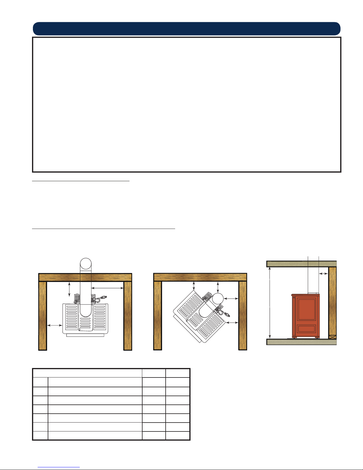
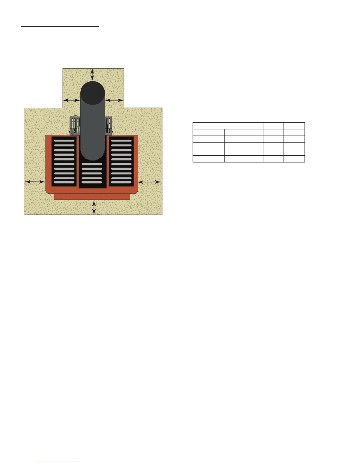
4.2 FREE STANDING STOVE INSTALLATION
A stove must never be installed in a hallway or near a staircase, since it may block the way in case of fi re or fail to respect required
clearances. It is of the utmost importance that the clearances to combustible materials be strictly adhered to during installation of the
stove. Refer to the table and diagrams below for minimum required clearances.
Ceiling / Plafond
Back wall / Arrière Mur
A
B
Side wall / Paroi Latérale
C
Side wall / Paroi Latérale
Side wall / Paroi Latérale
Dimension Inch mm
A Backwall to Stove 11 280
B Sidewall to Stove 7 178
C Sidewall to Flue 17.3 440
D Wall to Stove (Angled Installation) 3 77
E Wall to Flue (Angled Installation) 14.4 366
F Ceiling Height 84 2134
G Backwall to Flue 14.8 376
5
Back wall / Arrière Mur
D
E
E
F
D
Side wall / Paroi Latérale
Floor Protector / Protection de Plancher
• Do not place any combustible material within 4’ (1.2m) of
the front of the unit.
• The clearance between the fl ue pipe and a wall are valid only
for vertical walls and for vertical fl ue pipe.
• The chimney connector must not pass through an attic or roof
space, closet or similar concealed space, a fl oor, or a ceiling.
• For Canadian installations, where passage through a wall,
or partition of combustible construction is desired, the
installation must conform to CAN/CSA-B365.
• A fl ue pipe crossing a combustible wall must have a minimum
clearance of 18” (457.2mm).
• To reduce fl ue clearances from combustible materials, contact
your local safety department.
G
Back wall / Arrière Mur
4.4 FLOOR PROTECTOR
The stove must be placed on solid concrete, solid masonry, or when installed on a combustible fl oor, on a fl oor protector. The fl oor
protector is required to provide heat, live ember, and ash protection and must be of a non-combustible, continuous solid surface to
protect against infi ltration of live embers and ash. The stove must be placed on solid concrete, solid masonry, or when installed on a
combustible fl oor, on a Type 2 fl oor protector listed to standard UL 1618 with a minimum R value of 1.03 and a minimum thickness
of 1/2” or equivalent.
J
MM
Dimension Inch mm
H* Front 15 381
J Flue rear 2 51
K** Left 6 204
L** Right 6 204
M Flue Side 2 51
Canadian installations require 18” (457mm)
K
L
Canadian installations require 8” (203mm)
H
6
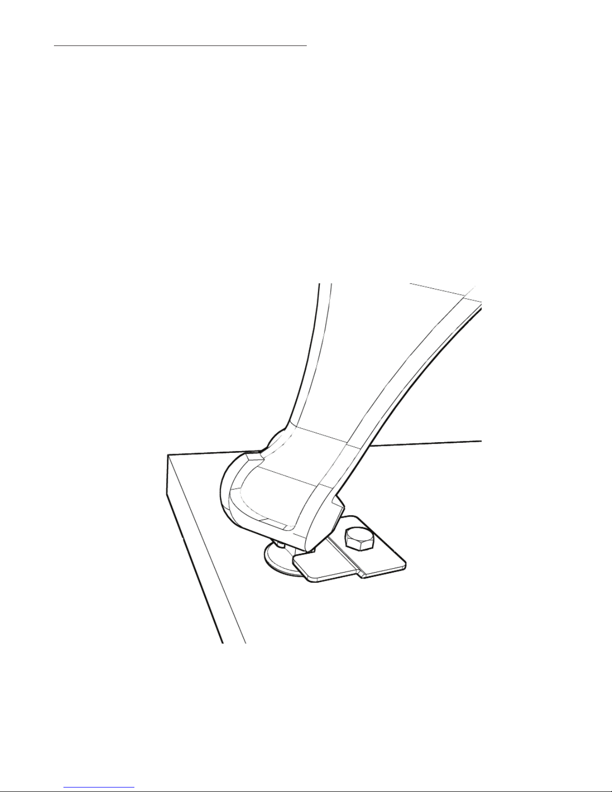
4.5 SPECIAL MOBILE HOME REQUIREMENTS
WARNING! - Do not install in a sleeping room
CAUTION! - The structural integrity of the mobile home fl oor, wall, and ceiling/roof must be maintained
In addition to the previously detailed installation requirements, mobile home installations must meet the following requirements:
• The heater must be permanently attached to the fl oor.
1. There are two holes in the pedestal base, use 3/8” bolts through the fl oor.
2. To attach the leg model use two 3/8-16 UNC bolts through the fl oor.
• The heater must be electrically grounded to the steel chassis of the mobile home with 8 GA copper wire using a serrated or star
washer to penetrate paint or protective coating to ensure grounding.
• When moving your mobile home, all exterior venting must be removed while the mobile home is being relocated. After relocation,
all venting must be reinstalled and securely fastened.
• Outside Air is mandatory for mobile home installation. See your dealer for purchasing.
• Check with your local building offi cials as other codes may apply.
.
7
MOBILE HOME ATTACHEMENT
5.0 VENTILATION
5.1 COMBUSTION AIR ASSEMBLY INSTRUCTIONS
This appliance requires a source of combustion air. If your home is of tight construction or has negative pressure problems, you
will need an outside source of air. Below is a list of possible indicators that a source of outside combustion air may be required.
1. Your stove does not draw steadily, smoke rollout occurs, wood burns poorly, or back-drafts occur whether or not there is
combustion present.
2. Existing fuel-fi red equipment in the house, such as fi replaces or other heating appliances, smell, do not operate properly, suffer
smoke roll-out when opened, or back-drafts occur whether or not there is combustion present.
3. Opening a window slightly on a calm (windless) day alleviates any of the above symptoms.
4. The house is equipped with a well-sealed vapor barrier and tight fi tting windows and/or has any powered devices that exhaust
house air.
5. There is excessive condensation on windows in the winter.
6. A ventilation system is installed in the house.
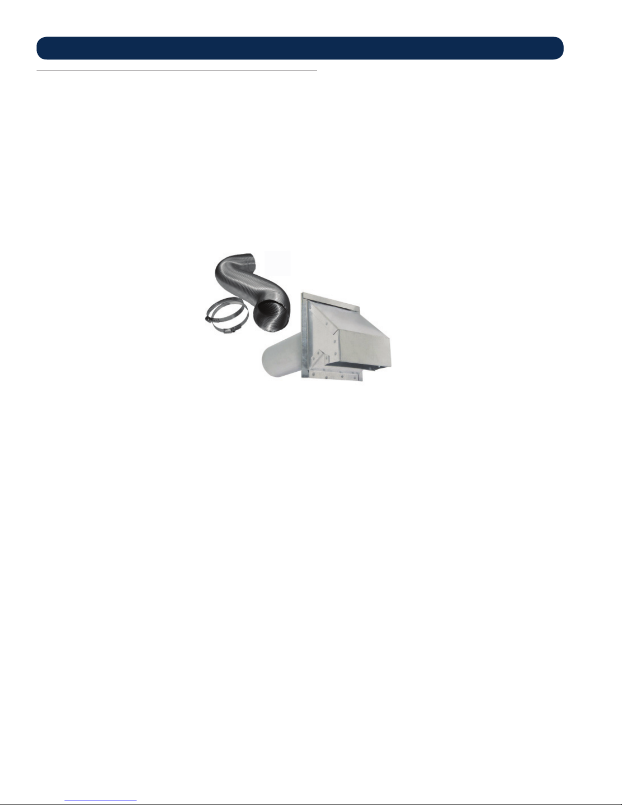
If an outside air intake is required. You may purchase a standard 4” Dryer Vent kit from your local hardware supply store.
“DRYER VENTING KIT”
INSTALLATION
If using a Dryer venting kit, the outlet cover must be of a design that DOES NOT close by means of a fl ap or trap door.
You must purchase a style that allows a continuous in-fl ow of air and that has a rodent screen.
“DRYER VENTING KIT” INSTALLATION:
Follow the manufacturer’s installation instructions for attaching the dryer vent kit to the home. Then attach it to the appliance.
8
 Loading...