

Breckwell SW940 Owner's Operation And Instruction Manual
OWNER’S OPERATION AND INSTRUCTION MANUAL
BRECKWELL
®
Exceptional Heat, Outstanding Value
MODEL: SW940
CAUTION!
Please read this entire manual before you install or use
your new room heater. Failure to follow instructions may
result in property damage, bodily injury, or even death.
Improper Installation Could Void Your Warranty!
SAFETY NOTICE:
If this heater is not properly installed, a house fire may
result. For your safety, follow the installation instructions.
Never use make-shift compromises during the installation of this
heater. Contact local building or fire officials about permits,
restrictions and installation requirements in your area.
SAFETY TESTED TO UL 1482-2011, ULC-S627-2000 and ULC-S628
US ENVIRONMENTAL PROTECTION AGENCY PHASE II CERTIFIED WOODSTOVE
THIS MANUAL WILL HELP YOU TO OBTAIN EFFICIENT, DEPENDABLE SERVICE FROM THE HEATER, AND ENABLE
YOU TO ORDER REPAIR PARTS CORRECTLY. KEEP IN A SAFE PLACE FOR FUTURE REFERENCE.
French version is available for download from the Breckwell website: http://www.breckwell.com/
La version française est disponible pour téléchargement à partir du site Breckwell: http://www.breckwell.com/
Breckwell
P.O. Box 750
Bridgeport, AL 35740
Phone: (866) 606-8444
www.BRECKWELL.com
Approved for installation in the USA and Canada
WASHINGTON STATE APPROVED
SAVE THESE INSTRUCTIONS
852080

CONGRATULATIONS!
You’ve purchased a heater from North America’s oldest manufacturer of wood burning products. By heating with wood you’re
helping to CONSERVE ENERGY! Wood is our only Renewable Energy Resource. Please do your part to preserve our wood supply.
Plant at least one tree each year. Future generations will thank you.
The instructions pertaining to the installation of your wood stove comply with UL-1482, ULC-S627 and ULC-S628 standards.
Combustible : Wood
Colors : Metallic Black
Flue Pipe Diameter : 8” (15.3cm)
Flue Pipe Type: (Standard Single Wall or Double Wall): Black or Blued Steel 2100°F (650°C)
Minimum Chimney Height : 12’ (3.7m)
Maximum Log Length : 23” (533mm)
Electrical 115V, 60Hz, 1.5A
Dimensions
Overall : (without Pedestal, Legs or Facade)
Depth x Width x Height :
Combustion Chamber :
Width x Depth :
Volume :
Cubic Feet:
Door Opening : Width x Height: 17” x 11” (431mm x 279mm)
Pyroceramic Glass Door : (Viewing) Width x Height: 16.5” x 10” (419mm x 254mm)
Weight (lbs): 450 lbs
31” x 33” x 25” (787mm x 838mm x 635mm)
25” x 21” (635mm x 533mm)
3.6 cubic feet
HOT WHILE IN OPERATION. KEEP CHILDREN, CLOTHING AND FURNITURE AWAY. CONTACT
DO NOT USE CHEMICALS OR FLUIDS TO IGNITE THE FIRE.
DO NOT LEAVE THE STOVE UNATTENDED WHEN THE DOOR IS SLIGHTLY OPENED.
DO NOT BURN GARBAGE, FLAMMABLE FLUID SUCH AS GASOLINE, NAPHTHA OR MOTOR OIL.
DO NOT CONNECT TO ANY AIR DISTRIBUTION DUCT OR SYSTEM.
ALWAYS CLOSE THE DOOR AFTER THE IGNITION.
2 Breckwell
CAUTIONS:
MAY CAUSE SKIN BURNS.
PRE-ASSEMBLY
UNPACK AND INSPECT
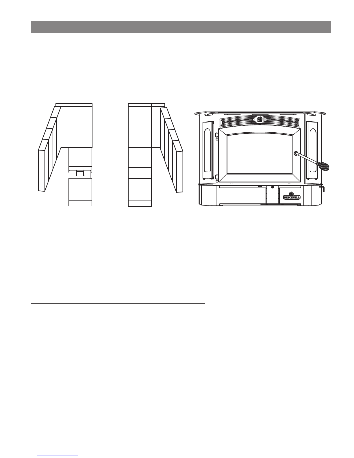
Remove the packing from the appliance and inspect for any damage. Your appliance is packed with the door handle in a nonoperational position for shipping purposes. The correct operating position is with the handle rod pointed towards the fl oor, at an
approximate angle as illustrated below. Ensure that the bricks are positioned correctly and not broken (see illustration for proper brick
arrangement). Make sure that the baffl e board, above the air tubes, is in place and undamaged. DO NOT remove the baffl e board.
Brick Confi guration
Door Handle Proper Operational Position
TOOLS AND MATERIALS NEEDED FOR INSTALLATION
You must choose one of the three offered kits:
A) Pedestal Kit (SA940P)
B) Leg Kit (SA940L)
C) Fireplace Insert (SA940i)
Refer to the instructions found inside each kit for proper assembly.
A 7/16” socket wrench
A 5/16” socket (Best if using a power drill and a socket bit)
A pair of pliers or channel-locks
A power drill with an 1/8” drill bit to install sheet metal screws into connector pipe.
Sheet metal screws
A non-combustible fl oor protector as specifi ed in this manual
All chimney and chimney connector components required for your particular venting installation.
Breckwell 3
FREE STANDING ASSEMBLY
ASSEMBLY INSTRUCTIONS
This appliance is offered in three different confi gurations of which you get to choose. You have the option to install your new heater
as a freestanding heater on a pedestal, on legs or as a fi replace insert. You must purchase the desired kit separately from your
appliance dealer. Read and follow the directions in this manual and inside the chosen kit to ensure proper assembly, installation
and operation of your new wood heater.
Caution! The appliance is very heavy.
The assistance from a second person is strongly suggested. Please use proper lifting technic when positioning the appliance for
assembly and installation. Several methods may be used to attach the legs and pedestal to the appliance. The safest method is to roll
the appliance on its back, then attach the chosen assembly. When using this method, you should fi rst remove the fi rebrick from the
unit so as to reduce weight and possible breakage. It will be required to raise the bottom of the unit up to attach two of the legs or
the pedestal. It is recommended that you use cardboard or other means of padding to protect the fi nish on your new stove.
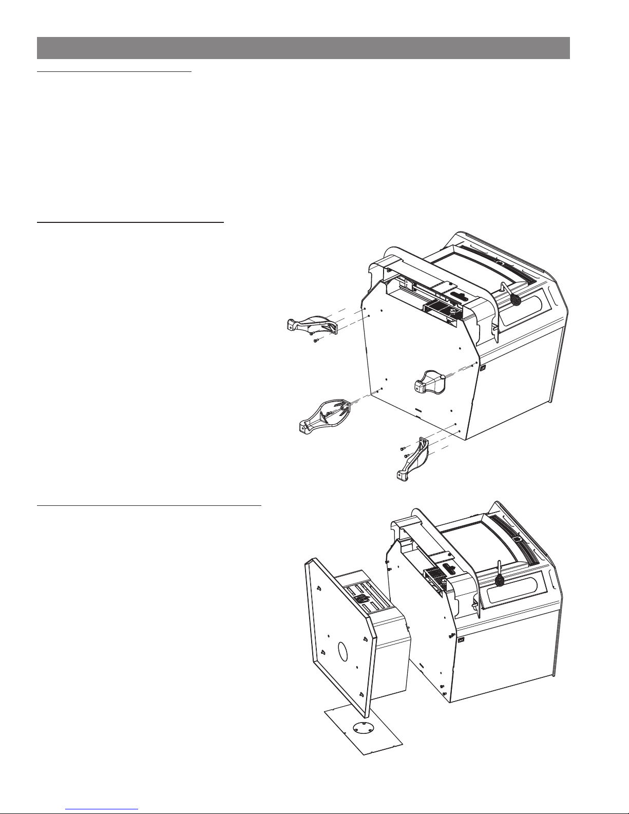
FREESTANDING LEG ASSEMBLY
Unpack the kit and ensure all components are present:
Four(4) Cast Iron Legs (40566), Eight(8) 1/4-20 UNC Bolts
(83339) and Eight(8) Flat Washers (83045A).
1) Position the unit for assembly.
2) Using the Eight(8) 1/4-20 bolts and washers provided,
attach the legs.
3) Rotate the appliance onto the legs, being careful not to
damage the legs while doing so.
4) Make sure that the baffl e board, above the air tubes, is
in place and undamaged. DO NOT remove the baffl e
board.
FREESTANDING PEDESTAL ASSEMBLY
Unpack the Pedestal Assembly and ensure all components are
present: One(1) Pedestal Assembly, Six(6) 1/4-20x1/2 Hex Head
Bolts, and Four(4) #10x1/2 Hex Head Self-tapping Screws. The
pedestal should come assembled to the base, ready to install on
your appliance. You can either roll the appliance onto its back as
above or locate the pedestal assembly in the approximate fi nal
location, then set the appliance atop the pedestal.
Caution! The appliance is very heavy.
1) Position the appliance for assembly.
2) Attach the pedestal to the bottom of the unit using four(4)
bolts provided.
3) Attach the pedestal back to the pedestal using four(4)
sheetmetal screws provided.
4) Make sure that the baffl e board, above the air tubes, is in
place and undamaged. DO NOT remove the baffl e board.
If an outside combustion air source is needed see the
“Combustion Air Assembly Instructions” section in this
manual.
4 Breckwell
FIREPLACE INSERT ASSEMBLY
INSERT FIREPLACE FACADE ASSEMBLY
Breckwell Room Heaters are available as an insert into existing masonry or factory-built fi replaces.
Do not alter the existing fi replace in any way either by removing bricks or mortar which could weaken the structural integrity
of the fi replace.
1) Position stove in fi replace. Align facade panels with fi replace and top of stove. The panels should be fl at against the fi replace
and standing vertical.
Notes: The side facade pieces go behind the top piece.
The facade must be installed before unit is set into its fi nal position.
2) Mark the location of the facade panels along the top of the stove with a pencil. The mark will be used to realign the panels later.
3) Slide stove out of fi replace far enough to be able to work behind facade panels.
4) Realign the fi rst side panel with the mark made previously.
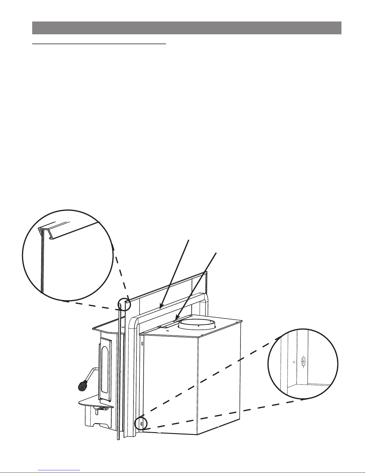
5) Using the predrilled holes in the facade panel as a guide; mark and drill holes for the self tapping screws used to mount the
facade panel. See illustration on right below.
Note: Align the mounting screws with the center of the predrilled holes to allow for adjustment.
6) Repeat steps 4 and 5 for the other side panel.
7) Attach side panel trim as shown. See illustration on left below.
8) Attach top panel retainer with two self tapping screws.
9) Ensure venting is attached properly.
10) Align the top panel with the retainer and side panels
11) Attach top panel trim.
Note: Stove and facade panels should realign with fi replace to allow the panels to be fl at against fi replace and standing vertically
12) Attach self adhesive insulation to back of facade and realign stove in fi replace.
Attach facade trim.
Self-adhesive insulation
Top Panel Retainer
Align mounting
screw with center
of predrilled
mounting hole.
Breckwell 5
INSTALLATION
SAFETY NOTICE
• IF THIS STOVE IS NOT PROPERLY INSTALLED, A HOUSE FIRE MAY RESULT. TO REDUCE THE RISK OF
FIRE, FOLLOW THE INSTALLATION INSTRUCTIONS.
• CONSULT YOUR MUNICIPAL BUILDING DEPARTMENT OR FIRE OFFICIALS ABOUT PERMITS,
RESTRICTIONS AND INSTALLATIONS REQUIREMENTS IN YOUR AREA.
• USE SMOKE DETECTORS IN THE ROOM WHERE YOUR STOVE IS INSTALLED.
• KEEP FURNITURE AND DRAPES WELL AWAY FROM THE STOVE.
• NEVER USE GASOLINE, GASOLINE-TYPE LANTERN FUEL, KEROSENE, CHARCOAL LIGHTER FLUID,
OR SIMILAR LIQUIDS TO START OR “FRESHEN UP” A FIRE IN THIS HEATER. KEEP ALL SUCH LIQUIDS
WELL AWAY FROM THE HEATER WHILE IT IS IN USE.
• IN THE EVENT OF A CHIMNEY FIRE, PUSH THE AIR CONTROL FULL CLOSED TO DEPRIVE THE FIRE OF
OXYGEN. CALL THE FIRE DEPARTMENT.
• DO NOT CONNECT TO ANY AIR DISTRIBUTION DUCT OR SYSTEM.
• A SOURCE OF FRESH AIR INTO THE ROOM OR SPACE HEATED SHALL BE PROVIDED WHEN REQUIRED.
• THIS STOVE IS NOT INTENDED FOR INSTALLATION IN MOBILE OR MANUFACTURED HOMES.
POSITIONING THE STOVE
It is very important to position the wood stove as close as possible to the chimney, and in an area that will favor the most effi cient
heat distribution possible throughout the house. The stove must therefore be installed in the room where the most time is spent, and
in the most spacious room possible. Recall that wood stoves produce radiating heat, the heat we feel when we are close to a wood
stove. A wood stove also functions by convection, that is through the displacement of hot air accelerated upwards and its replacement
with cooler air. If necessary, the hot air distribution from the stove may be facilitated by the installation of a blower.
• Route power cord away from unit.
• Do not route power cord under or in front of appliance.
• The wood stove must not be hooked up to a hot air distribution system since an excessive accumulation of heat may occur.
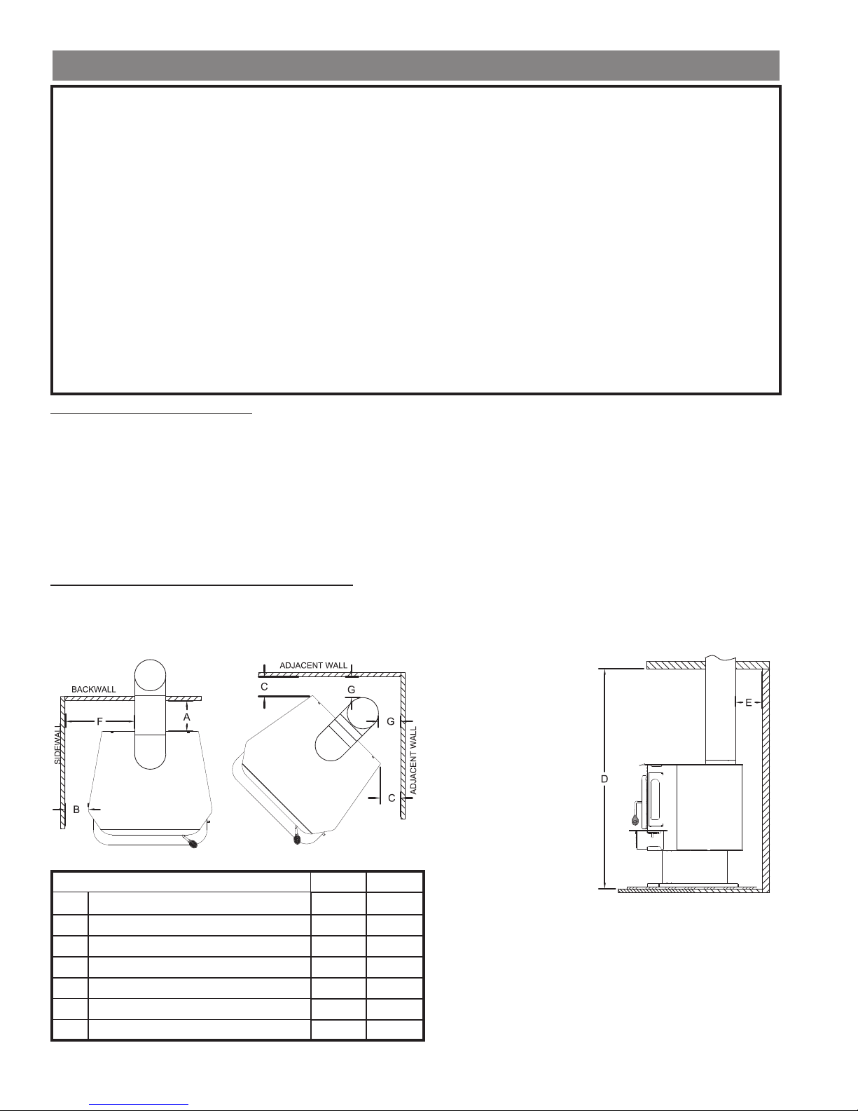
FREE STANDING STOVE CLEARANCES
A wood stove must never be installed in a hallway or near a staircase, since it may block the way in case of fi re or fail to respect
required clearances. It is of the utmost importance that the clearances to combustible materials be strictly adhered to during installation
of the stove. Refer to the table below for minimum required clearances.
• Do not place any
combustible material
within 4’ (1.2m) of the
front of the unit.
• The clearance between
the flue pipe and a wall
are valid only for vertical
walls and for vertical fl ue
pipe.
• The chimney connector
must not pass through an
attic or roof space, closet
Dimension Inch mm
A Backwall to Stove 23 584
B Sidewall to Stove 22 558
C Wall to corner (Angled Installation) 23 584
D Ceiling Height 84 2133
E Backwall to Flue 25 635
F Sidewall to Flue 35 889
G Wall to Flue (Angled Installation) 32 812
or similar concealed
space, a fl oor, or a ceiling.
• For Canadian installations, where passage through a wall,
or partition of combustible construction is desired, the
installation must conform to CAN/CSA-B365.
• A fl ue pipe crossing a combustible wall must have a minimum
clearance of 18” (457.2mm).
• To reduce fl ue clearances from combustible materials, contact
your local safety department.
6 Breckwell
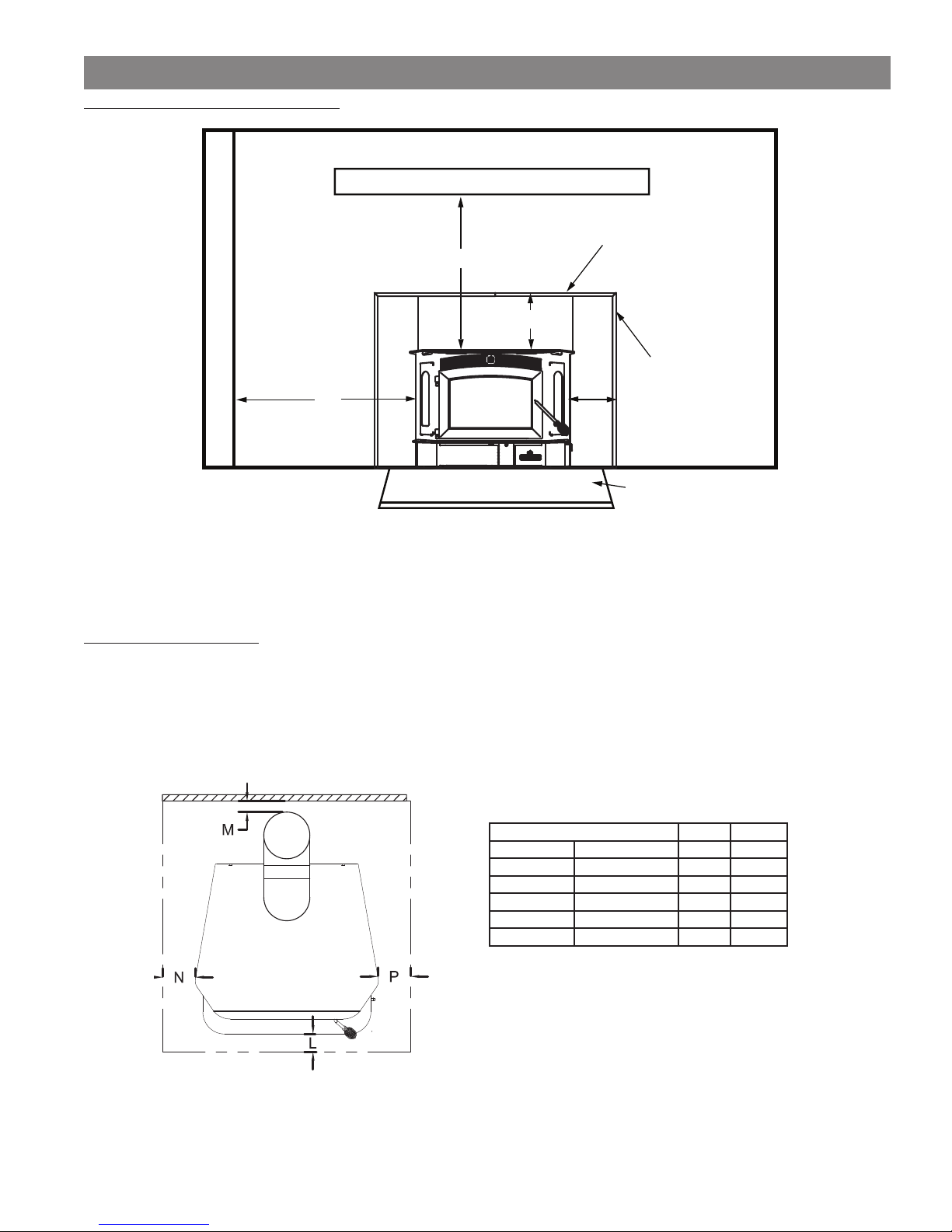
CLEARANCES TO COMBUSTIBLES
INSERT STOVE CLEARANCES
MANTEL
TOP TRIM
D
SIDE WALL
SIDE TRIM
A
A: Side wall: 18” (457mm) to side of appliance
B: Top Trim: 18” (457mm) above top of appliance
C: Side trim: 18” (457mm) to side of appliance
D: Mantle: 28” (711mm) above top of appliance
C
FLOOR PROTECTOR
FLOOR PROTECTOR
The stove must be placed on solid concrete, solid masonry, or when installed on a combustible fl oor, on a fl oor protector. The fl oor
protector is required to provide heat, live ember, and ash protection and must be of a non-combustible, continuous solid surface to
protect against infi ltration of live embers and ash. If a fl oor pad is used, it should be listed to UL 1618 (type 1 ember protection) or
equal. For UL Listed fl oor protectors, refer to manufacturers instructions for installation directions.
B
Breckwell 7
Dimension Inch mm
J Stove Width 33 838
K Stove Depth 31 787
L Front 16 406
M Back 0 0
N Left 8 203
P Right 8 203
Canadian installations require 18” (457mm)
Canadian installations require 8” (203mm)
VENTILATION
COMBUSTION AIR ASSEMBLY INSTRUCTIONS
This appliance requires a source of combustion air. If your home is of tight construction or has negative pressure problems, you
will need an outside source of air. Below is a list of possible indicators that a source of outside combustion air may be required.
1. Your stove does not draw steadily, smoke rollout occurs, wood burns poorly, or back-drafts occur whether or not there is
combustion present.
2. Existing fuel-fi red equipment in the house, such as fi replaces or other heating appliances, smell, do not operate properly, suffer
smoke roll-out when opened, or back-drafts occur whether or not there is combustion present.
3. Opening a window slightly on a calm (windless) day alleviates any of the above symptoms.
4. The house is equipped with a well-sealed vapor barrier and tight fi tting windows and/or has any powered devices that exhaust
house air.
5. There is excessive condensation on windows in the winter.
6. A ventilation system is installed in the house.
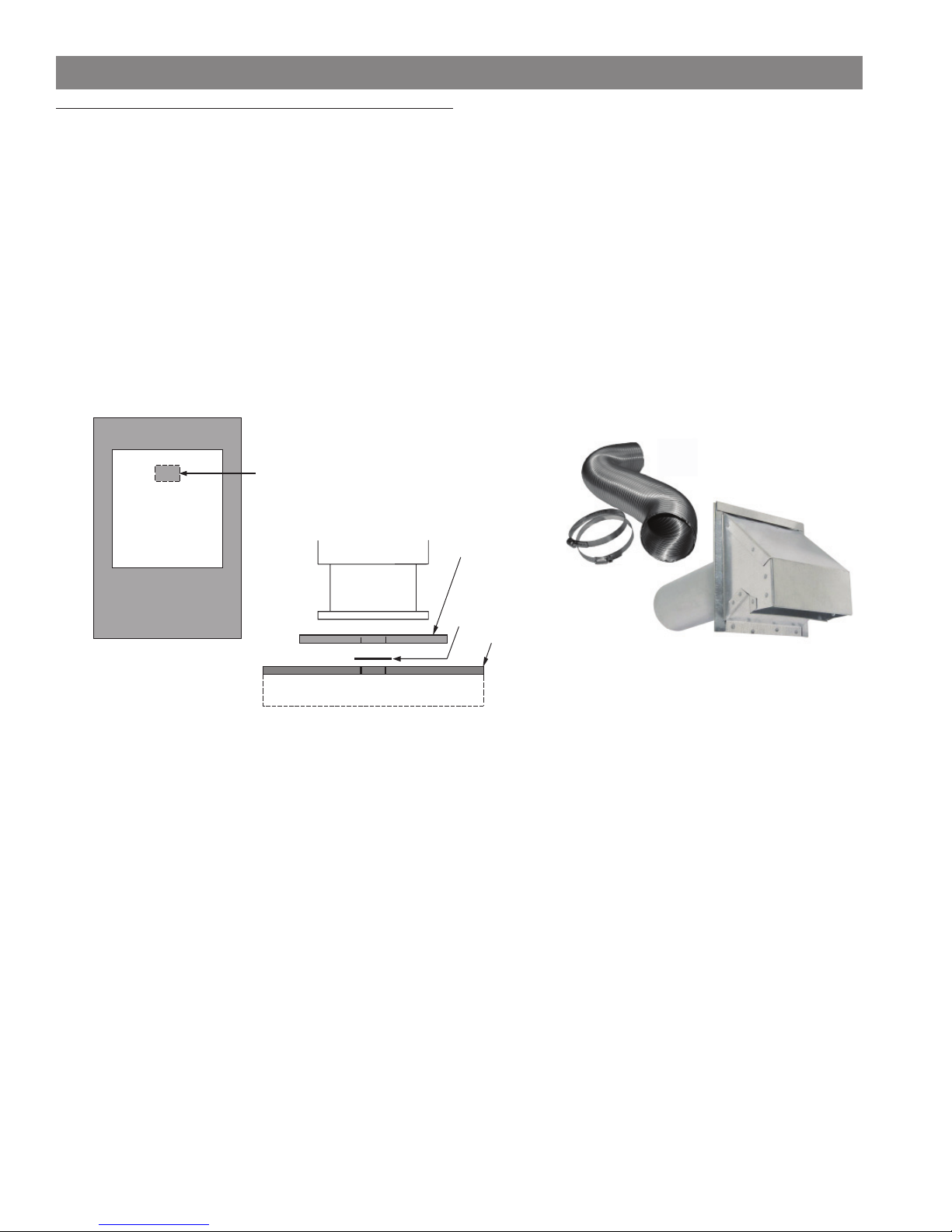
If an outside air intake is required. You have two options. You may cut a rectangular hole in the fl oor of your home and the fl oor
protector, or purchase a standard 4” Dryer Vent kit from your local hardware supply store and install it on the rear of the pedestal.
Make a 2” x 7” (51mm x 177mm)
cutout through both the oor
protector and home’s ooring
aligned with the knockout in
the pedistal base.
Non-Combustible Floor
FLOOR PROTECTOR
Rodent Screen
Home’s Floor
“Dryer Venting Kit” Installation
“Combustion Air thru Unit Base” Installation
If your choice is to cut a rectangular hole in the fl oor and fl ooring protector, refer to the above illustrations for assistance. You
must place a rodent screen between the fl oor protector and the fl oor to prevent passage of any unwanted vermin into your home.
If using a Dryer venting kit, the outlet cover must be of a design that DOES NOT close by means of a fl ap or trap door.
You must purchase a style that allows a continuous in-fl ow of air and that has a rodent screen.
“COMBUSTION AIR THROUGH UNIT BASE” INSTALLATION:
First, decide the location of the appliance. Then, cut a 2” x 7” rectangular opening in the fl oor protector within the appliance base’s
perimeter. Using the fl ooring protector as a template, position it in place and mark onto the fl oor of your home where to make your
next cut. Make the cut in your home’s fl oor slightly larger than the 2” x 7” to accommodate any misalignment. Attach a piece of
screen over the hole to prevent any unwanted vermin entering your home. Remove the knock-out from the bottom of the pedestal.
Complete your appliance installation.
“DRYER VENTING KIT” INSTALLATION:
First using a pair of pliers or other means, remove the metal plate from the back of the pedestal and bend the tabs out. Follow the
manufacturer’s installation instructions for attaching the dryer vent kit to the home. Then attach it to the appliance.
8 Breckwell
 Loading...