

Breckwell SW740 Owner's Operation And Instruction Manual
OWNER’S OPERATION AND INSTRUCTION MANUAL
If this heater is not properly installed, a house
fi re may result. For your safety, follow the
installation instructions. Never use make-shift
compromises during the installation of this
heater. Contact local building or fi re offi cials
about permits, restrictions and installation
requirements in your area.
BRECKWELL
Exceptional Heat, Outstanding Value
MODEL: SW740
CAUTION!
Please read this entire manual before you install
or use your new room heater.
instructions may result in property damage,
bodily injury, or even death.
Improper Installation Could Void
Your Warranty!
SAFETY NOTICE:
If this heater is not properly installed, a house
fi re may result. For your safety, follow the
installation instructions. Never use make-shift
compromises during the installation of this
heater. Contact local building or fi re offi cials
about permits, restrictions and installation
requirements in your area.
Failure to follow
®
SAFETY TESTED TO UL 1482-2011, UM-84, ULC-S627-2000, and ULC-S628
US ENVIRONMENTAL PROTECTION AGENCY PHASE II CERTIFIED WOODSTOVE
THIS MANUAL WILL HELP YOU TO OBTAIN EFFICIENT, DEPENDABLE SERVICE FROM THE HEATER, AND ENABLE
YOU TO ORDER REPAIR PARTS CORRECTLY. KEEP IN A SAFE PLACE FOR FUTURE REFERENCE.
French version is available for download from the Breckwell website: http://www.breckwell.com/
La version française est disponible pour téléchargement à partir du site Breckwell: http://www.breckwell.com/
Breckwell
P.O. Box 750
Bridgeport, AL 35740
Phone: (866) 606-8444
www.BRECKWELL.com
Approved for installation in the USA and Canada
WASHINGTON STATE APPROVED
MOBILE HOME APPROVED (U.S. ONLY)
SAVE THESE INSTRUCTIONS.
852053C

CONGRATULATIONS!
You’ve purchased a heater from North America’s oldest manufacturer of wood burning products.
By heating with wood you’re helping to CONSERVE ENERGY!
Wood is our only Renewable Energy Resource. Please do your part to preserve our wood supply. Plant at least one tree each year.
Future generations will thank you.
The instructions pertaining to the installation of your wood stove comply with UL-1482, UM-84, ULC-S627, and ULC-S628 standards.
Combustible : Wood
Colors : Metallic Black
Flue Pipe Diameter : 6” (15.3cm)
Flue Pipe Type: (Standard Single Wall or Double Wall): Black or Blued Steel 2100°F (650°C)
Minimum Chimney Height : 12’ (3.7m)
Maximum Log Length : 18” (457mm)
Electrical 115V, 60Hz, 0.55A
Dimensions
Overall : (without Pedestal, Legs or Facade)
Depth x Width x Height :
Combustion Chamber :
Width x Depth :
Volume :
Cubic Feet:
Door Opening : Width x Height: 17.5” x 10.5” (444mm x 266mm)
Pyroceramic Glass Door : (Viewing) Width x Height: 16.25” x 10” (412mm x 254mm)
Weight (lbs): 358 lbs
28” x 28” x 23” (711mm x 711mm x 578mm)
23” x 18” (584mm x 457mm)
2.6 cubic feet
• HOT WHILE IN OPERATION. KEEP CHILDREN, CLOTHING AND FURNITURE
AWAY. CONTACT MAY CAUSE SKIN BURNS.
• DO NOT USE CHEMICALS OR FLUIDS TO IGNITE THE FIRE.
• DO NOT LEAVE THE STOVE UNATTENDED WHEN THE DOOR IS SLIGHTLY
OPENED.
• DO NOT BURN GARBAGE, FLAMMABLE FLUID SUCH AS GASOLINE, NAPHTHA
OR MOTOR OIL.
• DO NOT CONNECT TO ANY AIR DISTRIBUTION DUCT OR SYSTEM.
• ALWAYS CLOSE THE DOOR AFTER THE IGNITION.
2 Breckwell
CAUTIONS:

WARRANTY INFORMATION CARD
Name__________________________________________ Telephone #: (_____)_____________
City____________________________________________ State_______ Zip_________________
Email Address __________________________________________________________________
Model # of Unit________________________________ Serial #___________________________
Fuel Type:
Wood Coal Pellet Gas Other _________________________
Place of Purchase (Retailer)______________________________________________________
City____________________________________________ State_______ Zip_________________
If internet purchase, please list website address___________________________________
Date of Purchase _______________________________________________________________
Reason for Purchase: Alternative Heat Main Heat Source
Decoration Cost Other _________________________
What was the determining factor for purchasing your new appliance?_______
I have read the owner’s manual that accompanies this unit and fully understand the:
Installation
Operation and Maintenance of my new appliance.
Print Name Signature Date
Please attach a copy of your purchase receipt.
Warranty not valid without a Proof of Purchase.
Warranty information must be received within 30 days of original purchase.
Detach this page from this manual, fold in half with this page to the inside and tape together. Apply a
stamp and mail to the address provided. You may use an envelope if you choose.
You may register online by going to www.breckwell.com
All information submitted will be kept strictly con dential. Information provided will not be sold for advertising purposes.
Contact information will be used solely for the purpose of product noti cations.
CUT HERE CUT HERE
Breckwell 3

Fold Here Fold Here
Fold Here
PLACE
STAMP
HERE
Breckwell
P.O. Box 750
Bridgeport, AL 35740
4 Breckwell
CUT HERE CUT HERE
Unpack and Inspect
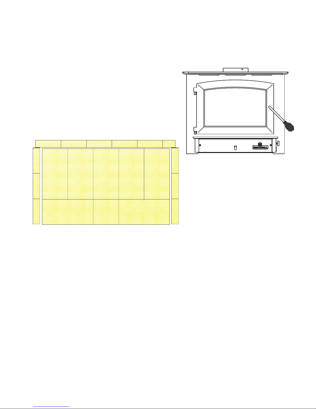
Remove the packing from the appliance and inspect for any damage. Your appliance is packed with the door handle in a nonoperational position for shipping purposes.
The correct operating position is with the handle rod pointed towards the fl oor, at an approximate angle as illustrated below.
Ensure that the bricks are positioned correctly and not broken (see illustration for proper brick arrangement). Make sure that the
baffl e board, above the air tubes, is in place and undamaged. (DO NOT REMOVE)
Door Handle Proper Operational Position
Brick Confi guration
Tools and Materials Needed For Installation
1. You must choose one of the three offered kits:
A) Pedestal Kit (SA740P)
B) Leg Kit (SA740L)
C) Fireplace Insert (SA740i)
Refer to the instructions found inside each kit for proper assembly.
2. A 7/16” socket wrench
3. Ruler / Measuring Tape
4. Furnace Cement
5. A 5/16” socket (Best if using a power drill and a socket bit)
6. A pair of pliers or channel-locks
7. A power drill with an 1/8” drill bit to install sheet metal screws into connector pipe.
8. Sheet metal screws
9. A non-combustible fl oor protector as specifi ed in this manual.
10. All chimney and chimney connector components required for your particular venting installation.
11. For mobile or manufactured home installations, see the MOBILE HOME section in this manual.
Breckwell 5
ASSEMBLY INSTRUCTIONS
This appliance is offered in three different confi gurations of which you get to choose. You have the option to install your new heater as
a freestanding heater on a pedestal, on legs or as a fi replace insert. You must purchase the desired kit separately from your appliance
dealer. Read and follow the directions in this manual and inside the chosen kit to ensure proper assembly, installation and operation
of your new wood heater.
Caution! The appliance is very heavy.
The assistance from a second person is strongly suggested. Please use proper lifting technic when positioning the appliance for
assembly and installation. Several methods may be used to attach the legs and pedestal to the appliance. The safest method is to roll
the appliance on its side, then attach the chosen assembly. When using this method, you should fi rst remove the fi rebrick from the
unit so as to reduce weight and possible breakage. It will be required to raise the bottom of the unit up to attach two of the legs or
the pedestal. It is recommended that you use cardboard or other means of padding to protect the fi nish on your new stove.
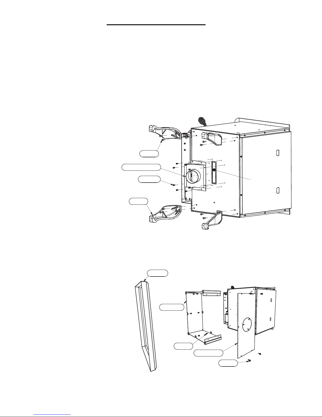
Free Standing Leg Assembly
Unpack the kit and ensure all components
are present: Four(4) Cast Iron Legs (40566),
Eight(8) 1/4-20 UNC Bolts (83339), Eight(8)
Flat Washers (83045A), One(1) Outside
Air Assembly (69848), and Eight (8) #10
Sheetmetal Screws (83343).
Bolt (83339)
1. Position the unit for assembly.
2. Using the Eight(8) 1/4-20 bolts and
OA Inlet Assembly (69848)
washers provided, attach the legs.
3. Using a pair of pliers or other means,
Screw (83343)
METAL PLATE
remove the metal plate from the bottom
of the appliance.
4. Attach the Outside Air Assembly to the
Leg (40566)
bottom of the appliance, making sure
the pipe is toward the rear of the unit.
Use the Eight(8) sheetmetal screws
provided.
5. Rotate the appliance onto the legs,
being careful not to damage the legs while doing so.
6. Make sure that the baffl e board, above the air tubes, is in place and undamaged. DO NOT remove the baffl e board.
Free Standing Pedestal Assembly
Unpack the Pedestal Assembly and ensure
all components are present: One(1) Pedestal
Assembly, Six(6) 1/4-20x1/2 Hex Head Bolts,
and Four(4) #10x1/2 Hex Head Self-tapping
Screws. e pedestal should come assembled
to the base, ready to install on your appliance.
You can either roll the appliance onto its side
as above or locate the pedestal assembly in
the approximate nal location, then set the
appliance atop the pedestal. Please heed the
caution above!
1. Position the appliance for assembly.
2. Using a pair of pliers or other means,
remove the metal plate from the bottom
of the appliance and the pedestal.
3. Attach the pedestal to the bottom of the
unit using three(3) bolts and washers
provided.
4. Attach the pedestal back to the pedestal using four(4) sheetmetal screws provided.
5. Make sure that the baffl e board, above the air tubes, is in place and undamaged. DO NOT remove the baffl e board.
6 Breckwell
Base (26298)
Pedistal (26299)
Bolt (83409)
Back Panel (26308)
Bolt (83343)
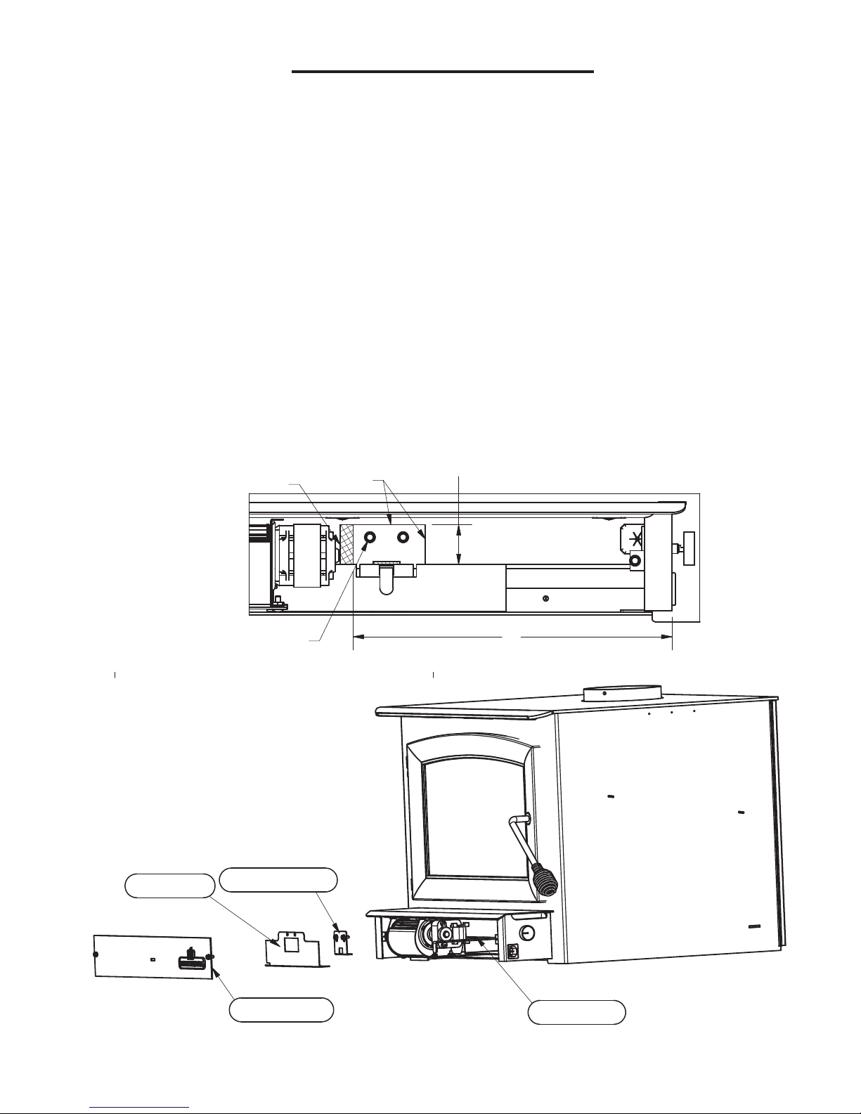
FIREPLACE INSERT ASSEMBLY
Air Dam Removal
For fi replace insert models, an air dam must be removed from the front of the stove.
1. On the front of the stove remove the two (2) screws holding the front plate(26302) in place.
2. Next make two cuts in the insulation(88190) measuring 2.5”(63mm) and 1.5”(38mm) as shown.
CAUTION: The insulation is held in place with sharp retaining studs. Use caution when removing the
insulation to avoid injury.
3. Pull back the insulation from the cuts and remove the damper plate(26304), air dam(26346), and the two retaining screws(83343)
located behind the insulation.
4. Reinstall the damper plate(26304) and retaining screws(83343).
5. Finally reinstall the front plate and the two retaining screws.
PULL BACK INSULATION
RETAINING SCREWS
BEHIND INSULATION
CUT HERE
1.50
12
Air Dam (26346)
Damper Plate (26304)
Front Plate (26302)
Breckwell 7
Insulation (88190)
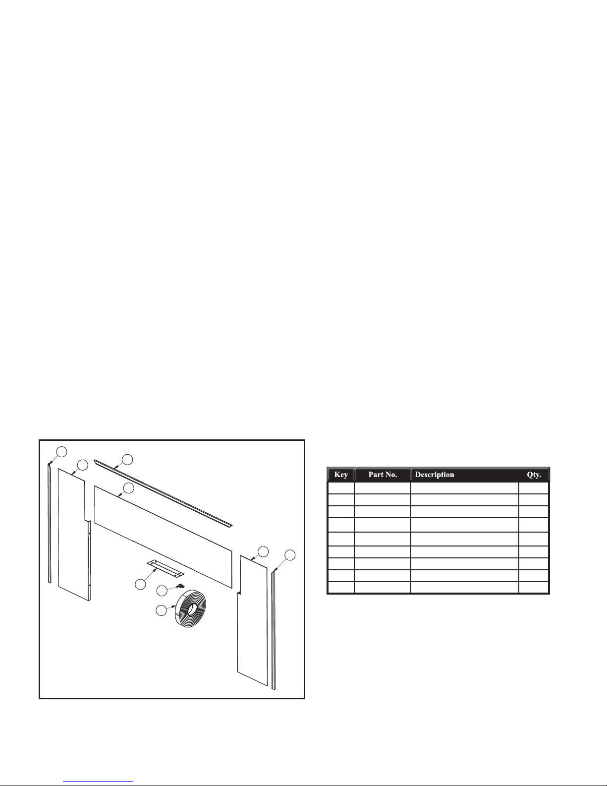
INSERT STOVE FACADE ASSEMBLY
Breckwell Room Heaters are available as an insert into existing masonry or factory-built fi replaces.
Do not alter the existing fi replace in any way either by removing bricks or mortar which could weaken the structural integrity
of the fi replace.
Note: The facade must be installed before unit is set into its fi nal position.
1) Position stove in fi replace. Align facade panels with fi replace and top of stove. The panels should be fl at against the fi replace
and standing vertical.
Notes: The side facade pieces go behind the top piece.
The facade must be installed before unit is set into its fi nal position.
2) Mark the location of the facade panels along the top of the stove with a pencil. The mark will be used to realign the panels later.
3) Slide stove out of fi replace far enough to be able to work behind facade panels.
4) Realign the fi rst side panel with the mark made previously.
5) Using the predrilled holes in the facade panel as a guide; mark and drill holes for the self tapping screws used to mount the
facade panel. See illustration on right below.
Note: Align the mounting screws with the center of the predrilled holes to allow for adjustment.
6) Repeat steps 4 and 5 for the other side panel.
7) Attach side panel trim as shown. See illustration on left below.
8) Attach top panel retainer with two self tapping screws.
9) Ensure venting is attached properly.
10) Align the top panel with the retainer and side panels
11) Attach top panel trim.
Note: Stove and facade panels should realign with fi replace to allow the panels to be fl at against fi replace and standing vertically
12) Attach self adhesive insulation to back of facade and realign stove in fi replace.
4
1
5
2
1 26278 Left Panel, Facade 1
2 26279 Central Panel, Facade 1
3 26277 Right Panel, Facade 1
4 892295-3 Trim, Facade Side-Left 1
5 892295-1 Trim, Facade Top 1
3
6
6 892295-2 Trim, Facade Right 1
7 88055 Gasket, Trim 10ft
9
8
7
8 83386 #10 X 3/4 Hex Head Screw 6
9 26414 Clamp, Top Trim 1
8 Breckwell
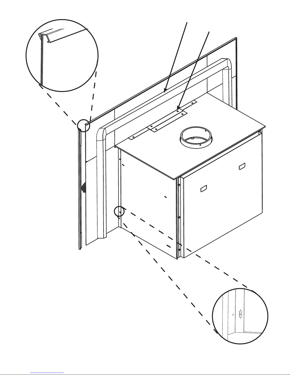
Attach facade trim.
Self-adhesive insulation
Top Panel Retainer
Breckwell 9
Align mounting
screw with center
of predrilled
mounting hole.
 Loading...