

Breckwell SW4100 Owner's Operation And Instruction Manual
Owner’s Operation and Instruction Manual
SAFETY NOTICE:
If this heater is not properly installed, a house re may
result. For your safety, follow the installation instructions. Never use make-shi compromises during the
installation of this heater. Contact local building or
re o cials about permits, restrictions and installation requirements in your area.
MODELS: SW4100
SAFETY TESTED TO UL 1482 and ULC-S627
US ENVIRONMENTAL PROTECTION AGENCY PHASE II CERTIFIED WOODSTOVE
WASHINGTON STATE APPROVED
CAUTION!
Please read this entire manual before you install or
use your new room heater. Failure to follow instruc-
tions may result in property damage, bodily injury,
or even death.
Improper Installation Could Void
SAFETY NOTICE:
If this heater is not properly installed, a house re may
result. For your safety, follow the installation instructions. Never use make-shi compromises during the
installation of this heater. Contact local building or
re o cials about permits, restrictions and installation requirements in your area.
Your Warranty!
SAVE THESE INSTRUCTIONS
THIS MANUAL WILL HELP YOU TO OBTAIN EFFICIENT, DEPENDABLE SERVICE FROM THE HEATER, AND ENABLE YOU TO OR-
DER REPAIR PARTS CORRECTLY. KEEP IN A SAFE PLACE FOR FUTURE REFERENCE.
e French version is available for download from the site Breckwell: http://www.breckwell.com/
La version française est disponible pour téléchargement à partir du site Breckwell: http://www.breckwell.com/
T
A
E
T
S
S
D
E
T
I
N
U
SS
UU
C
O
SS
M
P
CC
N
A
S
T
O
V
E
Y
Breckwell
227 Industrial Park Road P.O.
Box 151
South Pittsburg, TN 37380
Phone: (800) 750-2723
Web: www.BRECKWELL.com
851982 C

CONGRATULATIONS!
You’ve purchased a heater from North America’s oldest manufacturer of wood burning products.
By heating with wood you’re helping to CONSERVE ENERGY!
Wood is our only Renewable Energy Resource. Please do your part to preserve our wood supply. Plant at least one tree each year.
Future generations will thank you.
e instructions pertaining to the installation of your wood stove comply with UL-1482 and ULC-S627 standards.
Combustible : Wood
Colors : Metallic Black
Flue Pipe Diameter : 6” (15.3cm)
Flue Pipe Type: (Standard Single Wall or Double Wall): Black or Blued Steel 2100°F (650°C)
Minimum Chimney Hieght : 12’ (3.7m)
Maximum Log Length : 21” (53.4cm)
Dimensions
1
/
4
Overall :
32” x 27
Depth x Width x Height :
Combustion Chamber :
22
3
Width x Depth :
Volu m e :
3.11 ³ (.0881m³)
Cubic Feet:
Door Opening : Width x Height: 16” x 8” (41cm x 20cm)
Pyroceramic Glass Door : (Viewing) Width x Height: 14
7
Weight (lbs): 430 lbs (195kg)
” x 34-1/8” (81cm x 69cm x 87cm)
”
/
4
x 21” (578mm x 533mm)
1
”
”
x 9
/
8
(37cm x 23cm)
/
16
OPTIONAL ACCESSORIES
DESCRIPTION PART #
B36 Blower Assembly - 100 CFM 69354
Combustion Air Adapter 892021
CAUTIONS:
• HOT WHILE IN OPERATION. KEEP CHILDREN, CLOTHING AND FURNITURE AWAY.
CONTACT MAY CAUSE SKIN BURNS.
• DO NOT USE CHEMICALS OR FLUIDS TO IGNITE THE FIRE.
• DO NOT LEAVE THE STOVE UNATTENDED WHEN THE DOOR IS SLIGHTLY OPENED.
• DO NOT BURN GARBAGE, FLAMMABLE FLUID SUCH AS GASOLINE, NAPHTHA OR
MOTOR OIL.
• DO NOT CONNECT TO ANY AIR DISTRIBUTION DUCT OR SYSTEM.
• ALWAYS CLOSE THE DOOR AFTER THE IGNITION.
• THIS MODEL NOT APPROVED FOR MANUFACTURED OR MOBILE HOME INSTALLATION.
2 Ussc

WARRANTY INFORMATION CARD
Name__________________________________________ Telephone #: (_____)_____________
City____________________________________________ State_______ Zip_________________
Email Address __________________________________________________________________
Model # of Unit________________________________ Serial #___________________________
Fuel Type:
Wood Coal Pellet Gas Other _________________________
Place of Purchase (Retailer)______________________________________________________
City____________________________________________ State_______ Zip_________________
If internet purchase, please list website address___________________________________
Date of Purchase _______________________________________________________________
Reason for Purchase: Alternative Heat Main Heat Source
Decoration Cost Other _________________________
What was the determining factor for purchasing your new appliance?_______
I have read the owner’s manual that accompanies this unit and fully understand the:
Installation
Operation and Maintenance of my new appliance.
Print Name Signature Date
Please attach a copy of your purchase receipt.
Warranty not valid without a Proof of Purchase.
Warranty information must be received within 30 days of original purchase.
Detach this page from this manual, fold in half with this page to the inside and tape together. Apply a
stamp and mail to the address provided. You may use an envelope if you choose.
You may register online by going to www.usstove.com
All information submitted will be kept strictly con dential. Information provided will not be sold for advertising purposes.
Contact information will be used solely for the purpose of product noti cations.
CUT HERE CUT HERE
Ussc 3

Fold Here Fold Here
Fold Here
PLACE
STAMP
HERE
United States Stove Company
P.O. Box 151
South Pittsburg, TN 37380
4 Ussc
CUT HERE CUT HERE
Tools and Materials Needed For Installation
You will need a drill with a 1/8” bit to install sheet metal screws into connector pipe. A 5/16” socket/wrench or screw driver to install
pedestal trim, room air de ector, and blower assembly described below. A 1/2” socket/wrench to install ue collar. A non-combustible
oor protector as speci ed in this manual. All chimney and chimney connector components required for your particular chimney
installation.
Assembly
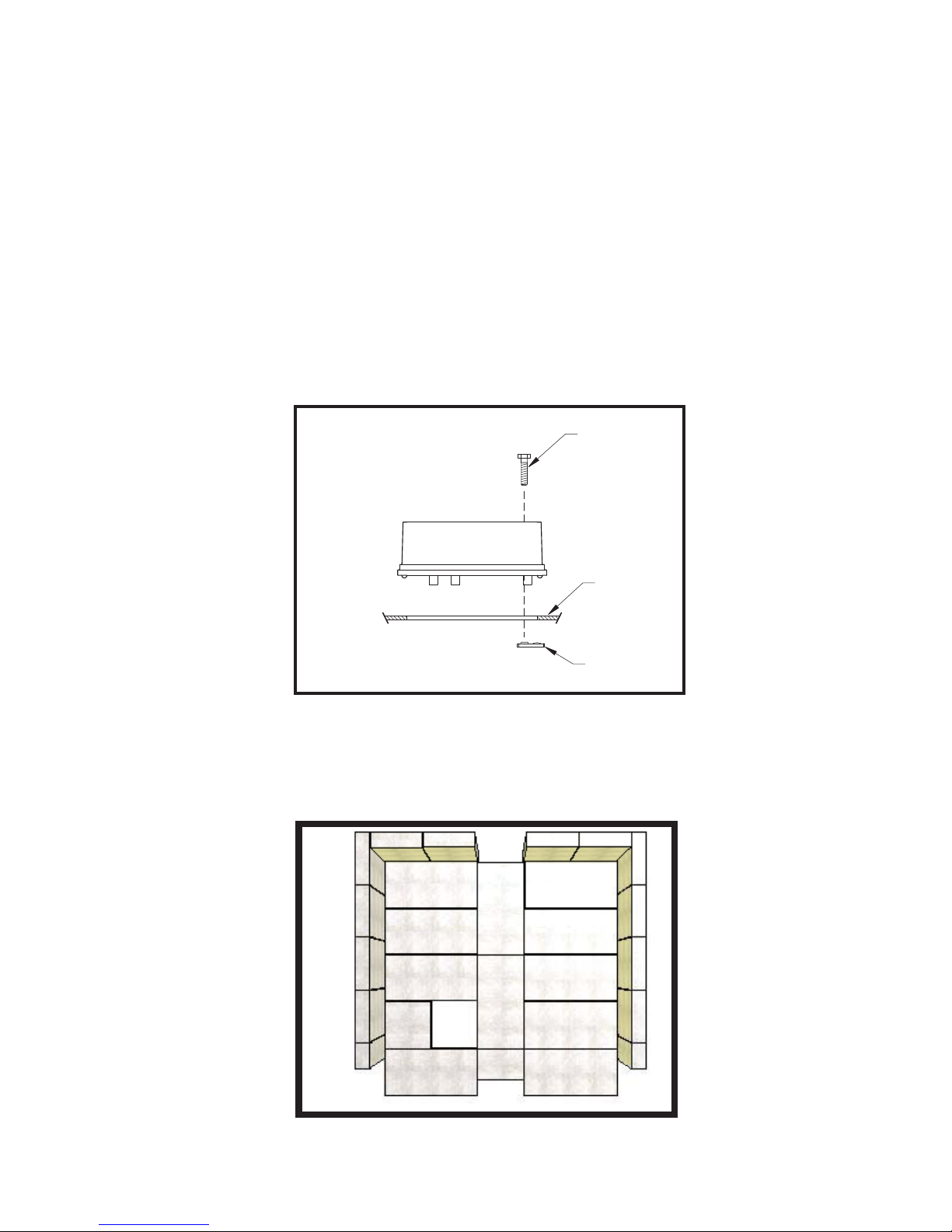
Flue Collar Assembly:
1. Mount the ue collar to the top of the unit as shown using the (3)
tabs
provided in the parts box.
Firebrick Con guration:
1. Replace the Firebrick as shown in the illustration below.
5/16-18 x 1-1/2 bolts, (3) washers, and (3) weld
Side view of fl ue collar
mount to heater top
Brick Confi guration
5/16-18 x 1-1/2
BOLT
HEATER
TOP
WELD
TAB
Ussc 5
ASSEMBLY INSTRUCTIONS
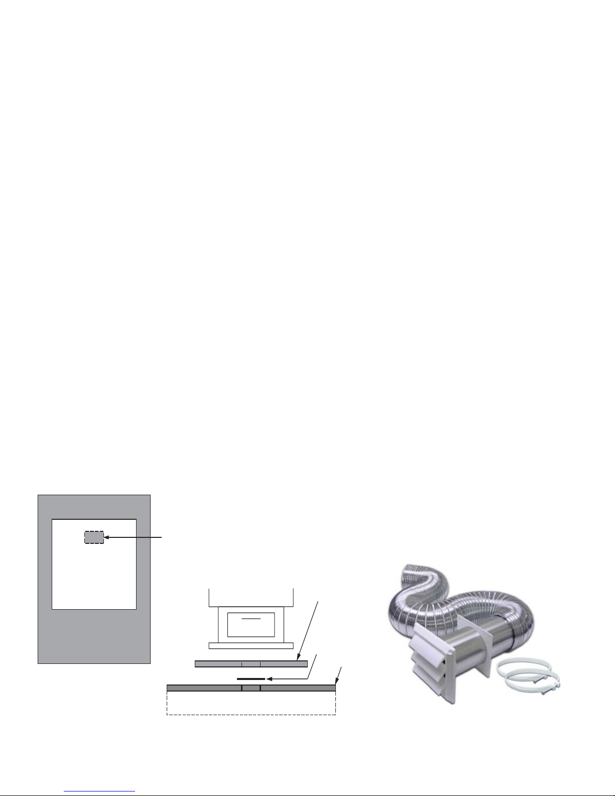
Combustion Air Intake
This appliance requires a source of combustion air. If you home is of tight construction or has negative pressure problems, you will need an outside source of air.
You have two options. You may cut a rectangular hole in the fl oor of your home and the fl oor protector, or
purchase a standard 4” Dryer Vent kit from your local hardware supply store and install it on the rear of the
pedestal.
If your choice is to cut a rectangular hole in the fl oor and fl ooring protector, refer to the below illustrations for
assistance. You must place a rodent screen between the fl oor protector and the fl oor to prevent passage of
any unwanted vermin into your home.
If using a Dryer venting kit, the outlet cover must be of a design that DOES NOT close by means of
a fl ap or trap door. You must purchase a style that allows a continuous in-fl ow of air and that has a rodent
screen. You will also need a Combustion Air Adapter to attach to the pedestal of the appliance. This adapter
can be purchased from your dealer.
If your home is not of tight construction, you can just simply remove the 4” round knockout in the rear of the
pedestal.
“Combustion Air thru Unit Base” installation:
First, decide the location of the appliance. Then, cut a 2” x 6” rectangular opening in the fl oor protector
within the appliance base’s perimeter. Using the fl ooring protector as a template, position it in place
and mark onto the fl oor of your home where to make your next cut. Make the cut in your home’s fl oor
slightly larger than the 2” x 6” to accommodate any misalignment. Attach a piece of screen over the
hole to prevent any unwanted vermin entering your home. Complete your appliance install.
“Dryer Venting Kit” installation:
Begin by installing the 4” adapter to the rear of the appliance using the screws provided. If not already ,
remove the round knock-out from the pedestal. Follow the manufacturer’s installation instructions for
attaching the dryer vent kit to the home. Then attach it to the adapter on the appliance.
Make a 2” x 6” (51mm x 152mm)
cutout through both the oor
protector and home’s ooring
within the perimeter of the
appliance’s base.
Non-Combustible Floor
FLOOR PROTECTOR
Rodent Screen
Home’s Floor
“Combustion Air thru Unit Base” Installation “Dryer Venting Kit” Installation
6 Ussc

INSTALLATION
THIS APPLIANCE SHOULD NOT BE USED AS THE PRIMARY HEAT SOURCE.
SAFETY NOTICE
• IF THIS STOVE IS NOT PROPERLY INSTALLED, A HOUSE FIRE MAY RESULT. TO REDUCE THE
RISK OF FIRE, FOLLOW THE INSTALLATION INSTRUCTIONS.
• CONSULT YOUR MUNICIPAL BUILDING DEPARTMENT OR FIRE OFFICIALS ABOUT PERMITS,
RESTRICTIONS AND INSTALLATIONS REQUIREMENTS IN YOUR AREA.
• USE SMOKE DETECTORS IN THE ROOM WHERE YOUR STOVE IS INSTALLED.
• KEEP FURNITURE AND DRAPES WELL AWAY FROM THE STOVE.
• NEVER USE GASOLINE, GASOLINE-TYPE LANTERN FUEL, KEROSENE, CHARCOAL LIGHTER
FLUID, OR SIMILAR LIQUIDS TO START OR “FRESHEN UP” A FIRE IN THIS HEATER. KEEP ALL
SUCH LIQUIDS WELL AWAY FROM THE HEATER WHILE IT IS IN USE.
• IN THE EVENT OF A CHIMNEY FIRE, PUSH THE AIR CONTROL FULL CLOSED TO DEPRIVE
THE FIRE OF OXYGEN. CALL THE FIRE DEPARTMENT.
• DO NOT CONNECT TO ANY AIR DISTRIBUTION DUCT OR SYSTEM.
• A SOURCE OF FRESH AIR INTO THE ROOM OR SPACE HEATED SHALL BE PROVIDED WHEN
REQUIRED.
POSITIONING THE STOVE
It is very important to position the wood stove as close as possible to the chimney and in an area that will favor
the most e cient heat distribution possible throughout the house. e stove must, therefore, be installed in the
room where the most time is spent and in the most spacious room possible. Recall that wood stoves produce
radiating heat, the heat we feel when we are close to a wood stove. A wood stove also functions by convection,
that is through the displacement of hot air accelerated upwards and its replacement with cooler air. If necessary,
the hot air distribution from the stove may be facilitated by the installation of a blower.
e wood stove must not be hooked up to a hot air distribution system since an excessive accumulation of heat
may occur.
A wood stove must never be installed in a hallway or near a staircase, since it may block the way in case of re
or fail to respect required clearances.
Ussc 7
FLOOR PROTECTOR
Your wood stove should be placed on a 1 inch, non-combustible surface with a k factor of 0.84. For multiple
layers, add R-values of each layer to determine the overall R-value. e R value for the required board is 1.2. If
there is a horizontal section of chimney connector, the oor protector should go under it and 2 inches beyond
each side.
Convert speci cation to R-value:
k-factor is given with a required thickness (T) in inches: R=1/k x T
C-factor is given: R=1/C
Example:
If the oor protector is 4” brick with a C-factor of 1.25 over 1/8” mineral board with a “k” factor of 0.29
the total R-value of the system is:
4” brick C=1.25, R=1/1.25=0.8
1/8” mineral board K=0.29, R=1/0.29 x 0.125=0.431
Total R = Rbrick + Rmineral = 0.8 + 0.431 = 1.231
Total R is greater than 1.2, the system is acceptable.
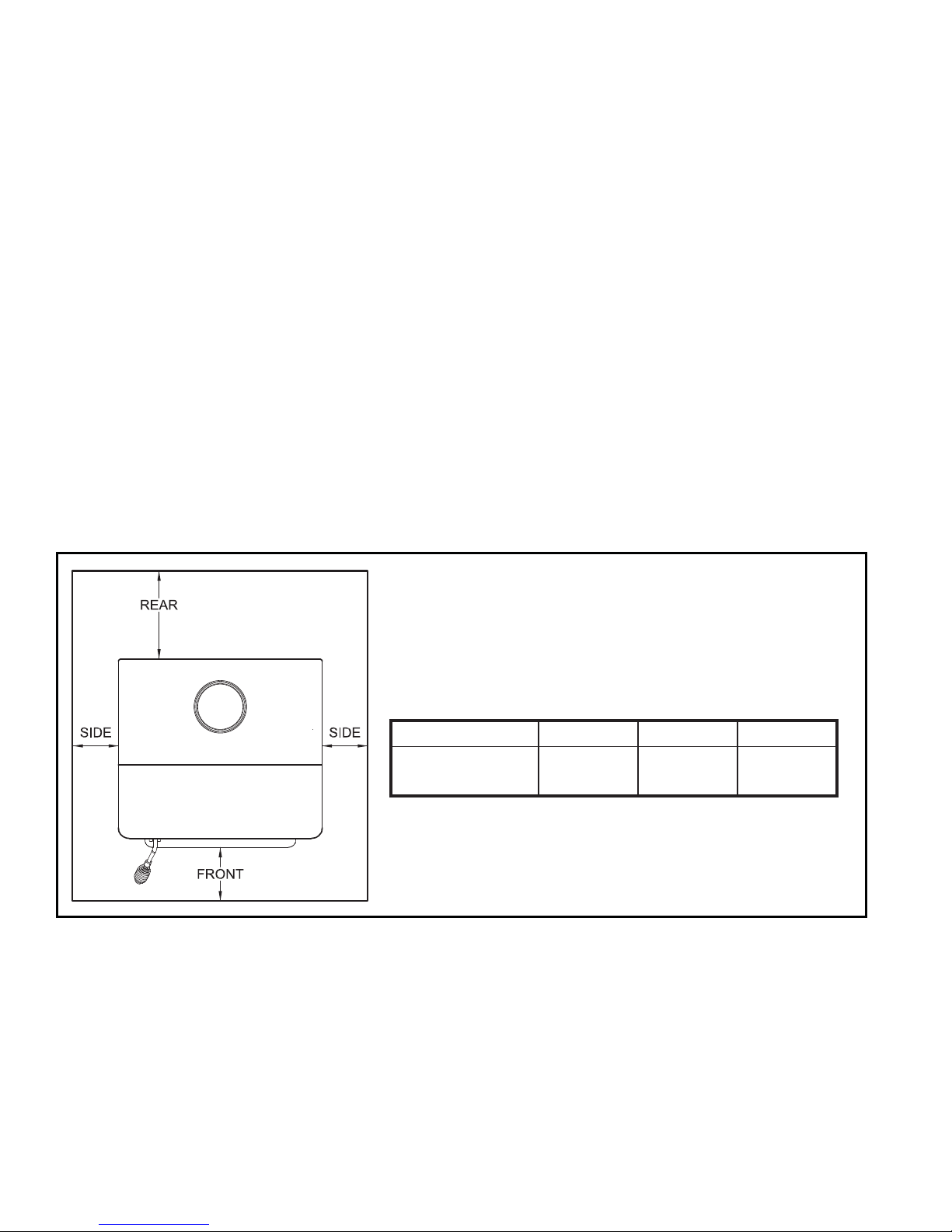
e oor protector should exceed the stove as follows:
e oor protector must be listed to UL1618.
Model Front Sides Rear
SW4100
26”
(660mm)8”(203mm)
(152mm)
- Canadian installations require 8” (203mm)
6”
8 Ussc
 Loading...