

Breckwell SPC50 Installation Manual
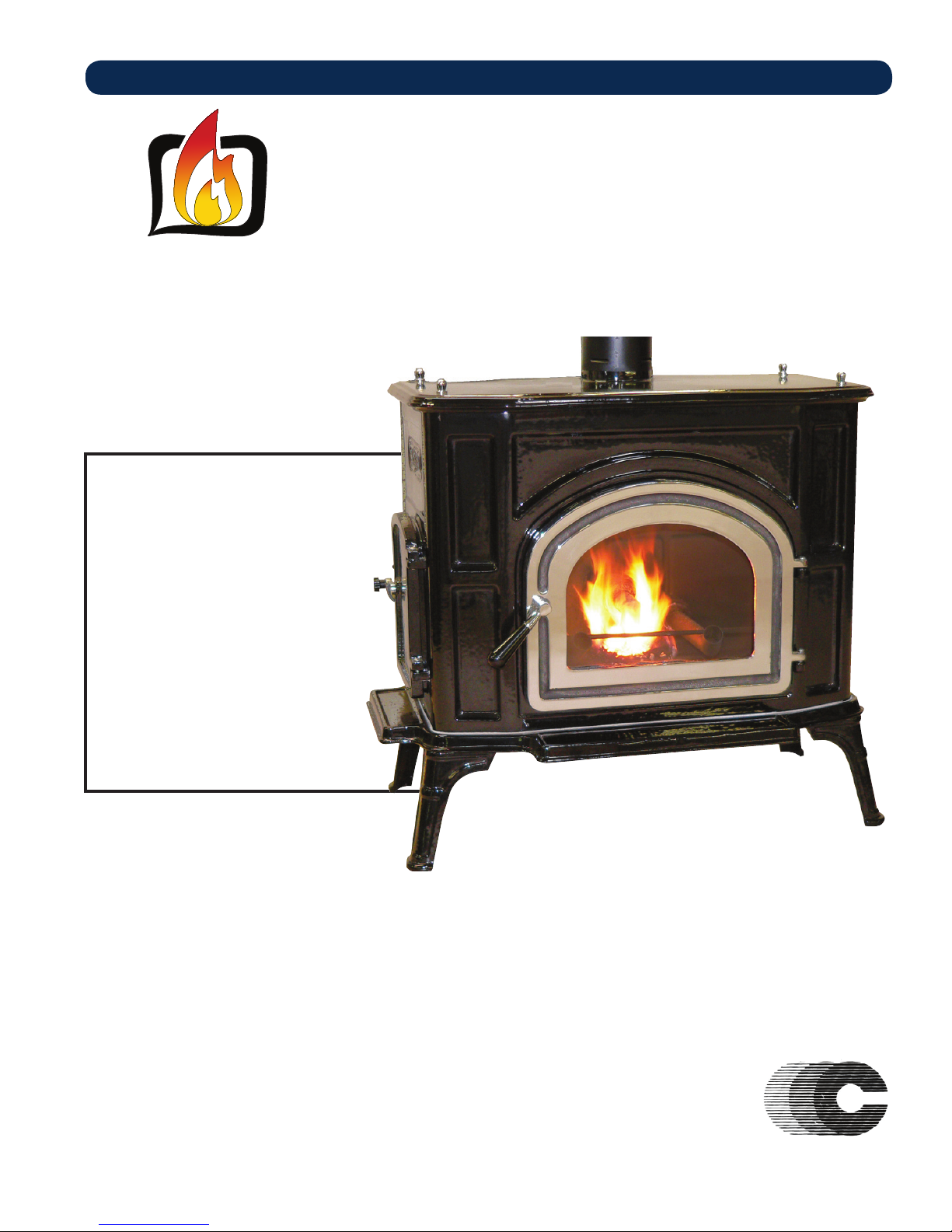
OWNER’S OPERATION AND INSTALLATION MANUAL
BRECKWELL
Exceptional Heat, Outstanding Value
MODEL: SPC50
Please read this entire manual before
installation and use of this pellet fuelburning room heater. Failure to follow
these instructions could result in property
damage, bodily injury, or even death.
Contact your local building or fire
offi cials about restrictions and installation
inspection requirements in your area.
Save these instructions.
This manual will help you to obtain effi cient,
dependable service from the heater,
and enable you to order repair parts
correctly. Keep in a safe place for future
reference.
®
Your pellet stove has been approved for installation in the USA and Canada. It may also be installed in a manufactured
or mobile home. Your stove conforms to ASTM E 1509, 2004, and Certifi ed to ULC S627, 2000, and(UM) 84-HUD
French version is available for download from the Breckwell website: http://www.Breckwell.com
La version française est disponible pour téléchargement à partir du site Breckwell: http://www.breckwell.com
Breckwell
227 Industrial Park Rd. P.O. Box 151 South Pittsburg, TN 37380
Phone (866) 606-8444 or (800) 750-2723
www.Breckwell.com
SAFETY AND EPA COMPLIANCE
This unit is not intended to be used as a primary source of heat.
Part No.: 852202 Rev A

SAFETY PRECAUTIONS
IMPORTANT: Read this entire manual before installing and
operating this product. Failure to do so may result in property
damage, bodily injury, or even death. Proper installation of
this stove is crucial for safe and effi cient operation.
Install vent at clearances specifi ed by the vent manufacturer.
Do not connect the pellet vent to a vent serving any other
appliance or stove.
DO NOT INSTALL A FLUE DAMPER IN THE EXHAUST
VENTING SYSTEM OF THIS UNIT.
Use of outside air is not required for this unit, unless installed
in an area with tight construction, or a mobile home.
Contact your local building offi cials to obtain a permit and
information on any additional installation restrictions or
inspection requirements in your area.
Do not throw this manual away. This manual has important
operating and maintenance instructions that you will need at
a later time. Always follow the instructions in this manual.
This appliance is designed for the use of pelletized fuel
that meet or exceed the standard set by the Pellet Fuel
Institute(PFI). The use of other fuels will void warranty.
Never use gasoline, gasoline-type lantern fuel, kerosene,
charcoal lighter fl uid, or similar liquids to start or ‘freshen
up’ a fi re in this heater. Keep all such liquids well away from
the heater while it is in use.
A working smoke detector must be installed in the same room
as this product.
Install a smoke detector on each fl oor of your home; incase of
accidental fi re from any cause it can provide time for escape.
The smoke detector must be installed at least 15 feet (4,57 M)
from the appliance in order to prevent unnecessary triggering
of the detector when reloading.
Do not unplug the stove if you suspect a malfunction. Turn
the ON/OFF SWITCH to “OFF” and contact your dealer.
Your stove requires periodic maintenance and cleaning (see
“MAINTENANCE ”). Failure to maintain your stove may
lead to improper and/or unsafe operation.
Disconnect the power cord before performing any
maintenance! NOTE: Turning the ON/OFF Switch to “OFF”
does not disconnect all power to the electrical components
of the stove.
Never try to repair or replace any part of the stove unless
instructions for doing so are given in this manual. All other
work should be done by a trained technician.
Do not operate your stove with the viewing door open. A
safety concern may arise from sparks or fumes entering the
room.
Allow the stove to cool before performing any maintenance
or cleaning. Ashes must be disposed in a metal container with
a tight fi tting lid. The closed container of ashes should be
placed on a non-combustible surface or on the ground, well
away from all combustible materials, pending fi nal disposal.
The exhaust system should be checked monthly during the
burning season for any build-up of soot or creosote.
Do not touch the hot surfaces of the stove. Educate all children
on the dangers of a high-temperature stove. Young children
should be supervised when they are in the same room as the
stove.
The hopper and stove top will be hot during operation; therefore,
you should always use some type of hand protection when
refueling your stove.
A power surge protector is required. This unit must be plugged
into a 110 - 120V, 60 Hz grounded electrical outlet. Do not use
an adapter plug or sever the grounding plug. Do not route the
electrical cord underneath, in front of, or over the heater. Do
not route the cord in foot traffi c areas or pinch the cord under
furniture.
The heater will not operate during a power outage. If a power
outage does occur, check the heater for smoke spillage and open
a window if any smoke spills into the room.
The feed door must be closed and sealed during operation.
Never block free airfl ow through the open vents of the unit.
Keep foreign objects out of the hopper.
The moving parts of this stove are propelled by high torque
electric motors. Keep all body parts away from the auger while
the stove is plugged into an electrical outlet. These moving parts
may begin to move at any time while the stove is plugged in.
Do not place clothing or other fl ammable items on or near this
stove.
When installed in a mobile home, the stove must be
grounded directly to the steel chassis and bolted to the fl oor.
WARNING—THIS UNIT MUST NOT BE INSTALLED IN
THE BEDROOM (per HUD requirements). CAUTION—
The structural integrity of the mobile home fl oor, wall, and
ceiling/roof must be maintained.
This appliance is not intended for commercial use.
CAUTION: Burning fuel creates carbon monoxide and can be
hazardous to your health if not properly vented.
This appliance should not be a primary source of heat as it is
possible to be down for maintenance and repairs.
* This appliance is a freestanding heater. It is not intended to be attached to any type of ducting. It is not a furnace.
2
SPECIFICATIONS
CONGRATULATIONS!
You’ve purchased a heater from North America’s oldest manufacturer of wood burning products.
By heating with wood you’re helping to CONSERVE ENERGY!
Wood is our only Renewable Energy Resource. Please do your part to preserve our wood
supply. Plant at least one tree each year. Future generations will thank you.
HEATING SPECIFICATIONS
Fuel Burn Rate* (lowest setting)
Burn Time (lowest setting)
Hopper Capacity
* Pellet size may effect the actual rate of fuel feed and burn times. Fuel feed rates may vary by as much as 20%. Use PFI listed fuel for best results.
1 Lb/Hr
60 Hrs
60 lbs. ( 27kg)
DIMENSIONS
Height 29
Width 31
Depth 29
Weight 360
ELECTRICAL SPECIFICATIONS
Electrical Rating 120Volt, 60Hz, 8Amp
Watts 96
FUEL CONSIDERATIONS
Your pellet stove is designed to burn premium hardwood pellets that comply with Association of Pellet Fuel Industries standards.
(Minimum of 40 lbs density per cubic ft, 1/4” to 5/16” diameter, length no greater than 1.5”, not less than 8,200 BTU/lb, moisture
under 8% by weight, ash under 1% by weight, and salt under 300 parts per million). Pellets that are soft, contain excessive amounts
of loose sawdust, have been, or are wet will result in reduced performance and excessive cleaning requirements of your appliance
and fl ue.
Store your pellets in a dry place. DO NOT store the fuel within the installation clearances of the unit or within the space required
for refueling and ash removal. Doing so could result in a house fi re.
Do not overfi re or use volatile fuels or combustibles, Doing so may cause personal and property damage hazards.
3

INSTALLATION
e
a
/
a
o
at
éa
e
INSTALLATION OPTIONS
Read this entire manual before you install and use your pellet stove. Failure to follow instructions may result in property
damage, bodily injury, or even death!
(See specifi c installation details for clearances and other installation requirements)
Your pellet stove may be installed to code in either a conventional or mobile home (see SPECIAL MOBILE HOME REQUIREMENTS).
The installation must comply with the Manufactured Home and Safety Standard (HUD), CFR3280, Part 24.
It is recommended that only an authorized technician install your pellet stove, preferably an NFI certifi ed specialist.
DO NOT CONNECT TO OR USE IN CONJUNCTION WITH ANY AIR DISTRIBUTION DUCTWORK UNLESS
SPECIFICALLY APPROVED FOR SUCH INSTALLATIONS.
The use of make-shift or other components other than stated herein could cause bodily harm, heater damage, and void your warranty.
IMPROPER INSTALLATION: The manufacturer will not be held responsible for damage caused by the malfunction
of a stove due to improper venting or installation. Call Customer Service and/or consult a professional installer if you
have any questions.
POSITIONING THE STOVE
It is very important to position the stove as close as possible to the chimney, and in an area that will favor the most effi cient heat
distribution possible throughout the house. The stove must therefore be installed in the room where the most time is spent, and in
the most spacious room possible. Recall that stoves produce radiating heat, the heat we feel when we are close to a stove. A stove
also functions by convection, that is through the displacement of hot air accelerated upwards and its replacement with cooler air.
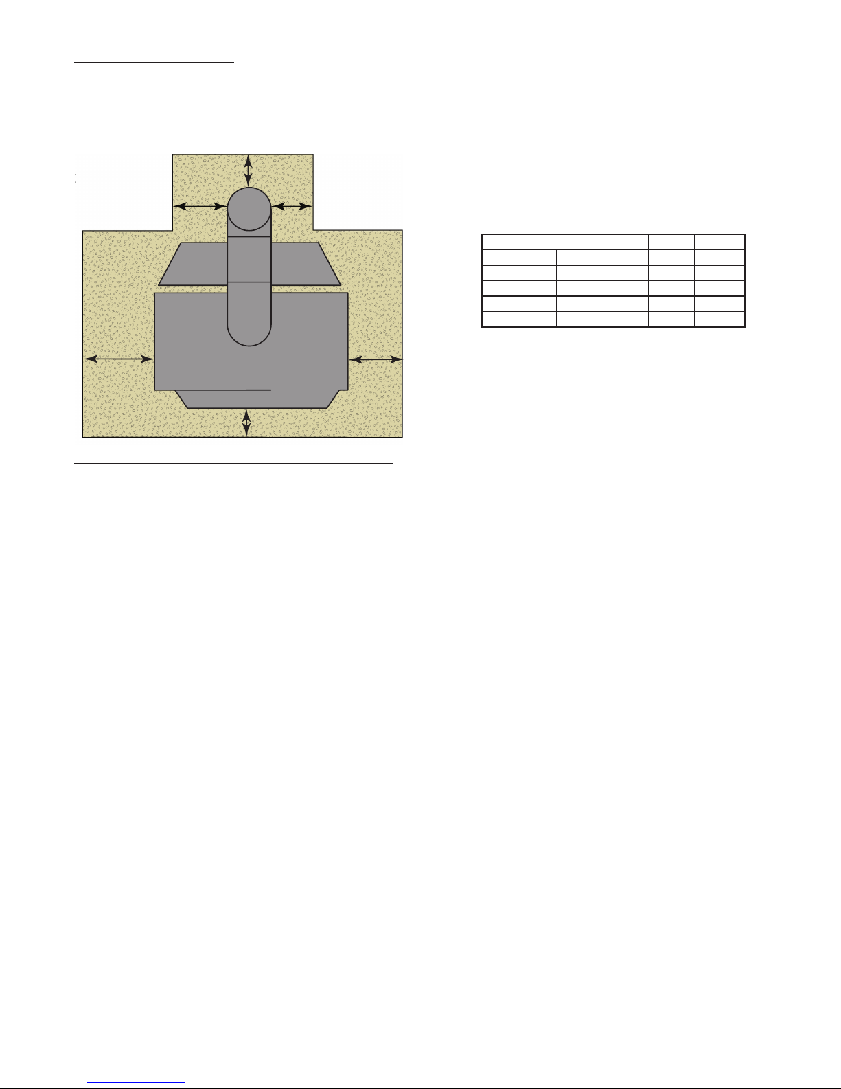
FREE STANDING STOVE INSTALLATION
A stove must never be installed in a hallway or near a staircase, since it may block the way in case of fi re or fail to respect required
clearances. It is of the utmost importance that the clearances to combustible materials be strictly adhered to during installation of
the stove. Refer to the table and diagrams below for minimum required clearances. Any reduction in clearance to combustibles may
only be done by means approved by a regulatory authority. Install vent at clearances specifi ed by the vent manufacturer.
Ceiling / Plafond
Back wall / Arrière Mur
Back wall / Arrière Mur
F
D
Side wall / Paroi Latérale
A
B
C
Side wall / Paroi Latérale
Side wall / Paroi Latérale
Dimension Inch mm
A Backwall to Stove 1 26
B Sidewall to Stove 12 305
C Sidewall to Flue* 377
D Wall to Stove (Angled Installation) 1 26
E Wall to Flue (Angled Installation)* 377
F Backwall to Flue* 3 77
• * Pellet type “L” vent must have 3” (77mm) clearance
• “Close Clearance “double wall vent must have 6”(151mm) clearance.
• “Single wall” smoke pipe must have 18” (458mm) clearance.
• Unless stated otherwise by the vent manufacturer.
E
E
D
Side wall / Paroi Latérale
Floor Protector / Protection de Plancher
• Do not place any combustible material within 4’
(1.2m) of the front of the unit.
• The clearance between the fl ue pipe and a wall are
valid only for vertical walls and for vertical fl ue
pipe.
• The chimney connector must not pass through an
attic or roof space, closet or similar concealed space,
or a fl oor, or ceiling.
• For Canadian installations, where passage through
a wall, or partition of combustible construction is
desired, the installation must conform to CAN/
CSA-B365.
• A fl ue pipe crossing a combustible wall must have
a minimum clearance of 18” (457.2mm).
• To reduce flue clearances from combustible
materials, contact your local regulatory authority.
Back wall / Arrière Mur
4
FLOOR PROTECTION
This heater must have a non-combustible fl oor protector (ember protection) installed beneath it, if the fl oor is of combustible
material. If a fl oor pad is used, it should be UL listed or equal. The fl oor pad or non-combustible surface should be large enough
to cover at least the area under the product and extend beyond the front and each side of the fuel loading and ash removal openings
as shown below. A Floor Protector of ¼ inch thick is recommended for this installation.
k wall / Arrière Mur
MM
K
J
Dimension Inch mm
H* Front 6 153
J Flue rear 2 51
K** Left 6 153
L** Right 6 153
M Flue Side 2 51
Canadian installations require 18” (457mm)
L
H
Canadian installations require 8” (203mm)
SPECIAL MOBILE HOME REQUIREMENTS
WARNING! - DO NOT INSTALL IN A SLEEPING ROOM
CAUTION! - THE STRUCTURAL INTEGRITY OF THE MOBILE HOME FLOOR, WALL, AND CEILING/ROOF
MUST BE MAINTAINED.
In addition to the previously detailed installation requirements, mobile home installations must meet the following requirements:
1) The heater must be permanently attached to the fl oor.
2) The heater must be electrically grounded to the steel chassis of the mobile home with 8 GA copper wire using a serrated or star
washer to penetrate paint or protective coating to ensure grounding.
3) When moving your mobile home, all exterior venting must be removed while the mobile home is being relocated. After relocation,
all venting must be reinstalled and securely fastened.
4) Outside Air is mandatory for mobile home installation. See your dealer for purchasing.
5) Check with your local building offi cials as other codes may apply.
5
VENTILATION
OUTSIDE AIR SUPPLY (Optional, unless installing in a mobile home)
Adequate ventilation air is required to operate this heater. During operation, the heater draws air for combustion which can be
assisted by the installation of outside combustion air inlets. However, certain weather conditions such as icing or use of kitchen
exhaust fans may impact and reduce the effectiveness of vents. It is important to note that room air starvation will negatively impact
the operation of the heater. Depending on your location and home construction, outside air may be necessary for optimal performance
Below is a list of possible indicators that a source of outside combustion air may be required.
1) Your stove does not draw steadily, smoke rollout occurs, wood burns poorly, or back-drafts occur whether or not there is
combustion present.
2) Existing fuel-fi red equipment in the house, such as fi replaces or other heating appliances, smell, do not operate properly, suffer
smoke roll-out when opened, or back-drafts occur whether or not there is combustion present.
3) Opening a window slightly on a calm (windless) day alleviates any of the above symptoms.
4) The house is equipped with a well-sealed vapor barrier and tight fi tting windows and/or has any powered devices that exhaust
house air.
5) There is excessive condensation on windows in the winter.
6) A ventilation system is installed in the house.
If an outside air intake is required.
• Metal pipe (solid or fl exible) must be used for the outside air installation.
• PVC pipe is NOT approved and should NEVER be used.
• A wind shield over the termination of the outside air pipe or a 90-degree elbow or bend away from the prevailing winds MUST
be used when an outside air pipe is installed through the side of a building.
• The outside air termination MUST be at least 1ft (0.305m) away from the exhaust system termination.
The outside air pipe on your heater is 4” (101mm) OD. The outside air connecting pipe must have an ID equal to the OD of the
outside air pipe on your heater. The outside air connection used MUST NOT restrict the amount of air available to your heater. The
outside air connecting pipe must be as short and free of bends as possible, and it must fi t over, not inside, the outside air connection
to the heater.
13.5
12.5
TYPICAL FRESH AIR TERMINATION
4.7
2.7
NOTE: DIMENSIONS TO YOUR
STOVES INLET/EXHAUST PIPES
ARE APPROXIMATE AND MAY VARY
DEPENDING ON YOUR INSTALLATION.
6
CHIMNEY CONNECTOR (STOVE PIPE)
Your chimney connector and chimney must have a diameter of 4” - 6”. If this is not the case, we recommend you contact your
dealer in order to insure there will be no problem with the draft.
The stove pipe must be made of aluminized or cold roll steel with a minimum thickness of 0.021” or 0.53 mm. It is strictly forbidden
to use galvanized steel.
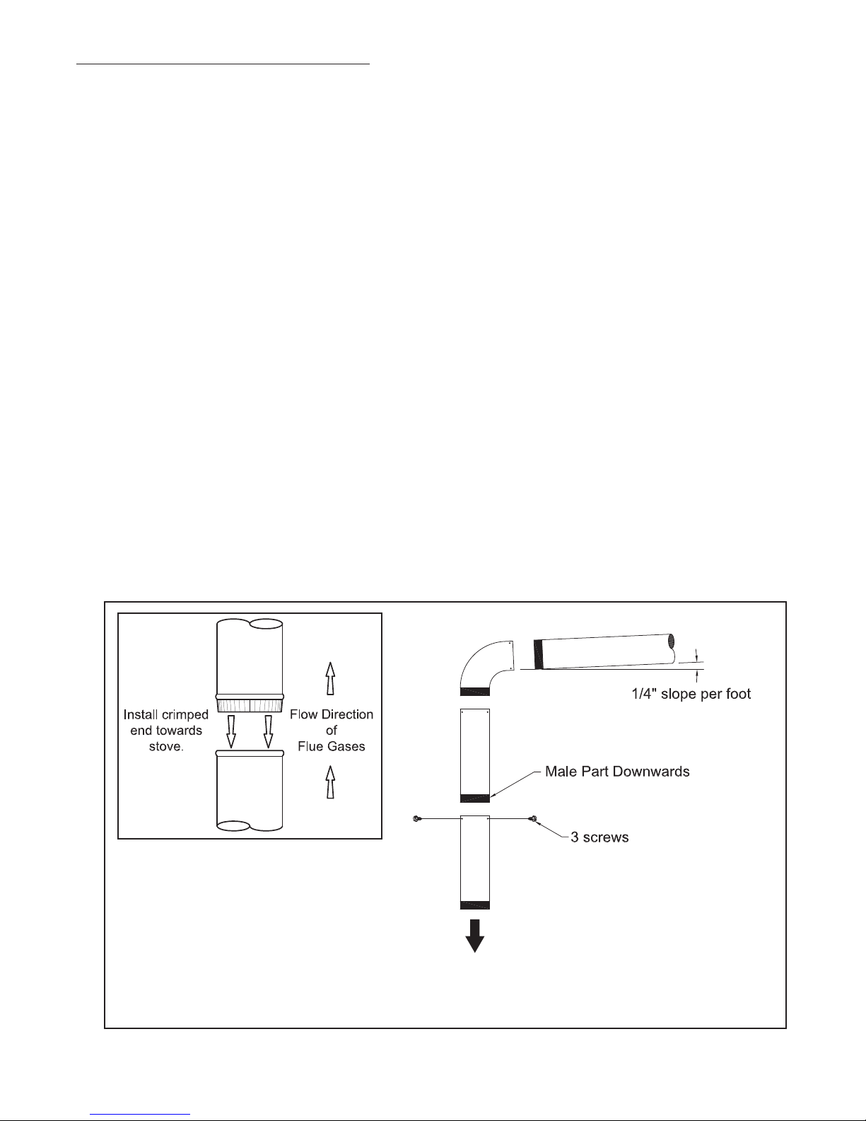
Your stove pipe should be assembled in such a way that the male section (crimped end) of the pipe faces down. Attach each of the
sections to one another with three equidistant metal screws. Seal the joints with furnace cement.
All sections installed horizontally must slope at least 1/4 inch per foot, with the upper end of the section toward the chimney.
Any installation with a horizontal run of stove pipe must conform to NFPA 211. You may contact NFPA (National Fire Protection
Association) and request the latest edition of the NFPA Standard 211.
To insure a good draft, the total length of the stove pipe should never exceed 8’ to 10’ (2.4m to 3.04 m). (Except for cases of
vertical installation, cathedral-roof style where the smoke exhaust system can be much longer and connected without problem to
the chimney at the ceiling of the room).
There should never be more than two 90 degrees elbows in the smoke exhaust system.
Installation of a “barometric draft stabilizer” (fi replace register) on a smoke exhaust system is prohibited.
Furthermore, installation of a draft damper is not recommended. With a controlled combustion wood stoves the draft is regulated
upon intake of the combustion air in the stove and not at the exhaust.
7
To
Appliance
PELLET VENT TYPE
A UL listed 4-inch or 6-inch type “PL” pellet vent exhaust system may be used for installation and attached to the pipe connector
provided on the stove. Connection at stove must be sealed using Hi-Temp RTV. Use 6-inch vent if the vent height is over 12-feet
or if the installation is over 2,500 feet above sea level.
We recommend the use of Simpson Dura-Vent® or Metal-Fab® pipe (if you use other pipe, consult your local building codes
and/or building inspectors). Do not use Type-B Gas Vent pipe or galvanized pipe with this unit. The pellet vent pipe is designed to
disassemble for cleaning and should be checked several times during the burning season. Pellet vent pipe is not furnished with the
unit and must be purchased separately.
PELLET VENT INSTALLATION
The installation must include a clean-out tee to enable collection of fl y ash and to permit periodic cleaning of the exhaust system.
90-degree elbows accumulate fl y ash and soot, thereby reducing exhaust fl ow and performance of the stove. Each elbow or tee
reduces draft potential by 30% to 50%.
All joints in the vent system must be fastened by at least 3 screws, and all joints must be sealed with Hi-Temp RTV silicone sealant
to be airtight. The area where the vent pipe penetrates to the exterior of the home must be sealed with silicone or other means to
maintain the vapor barrier between the exterior and the interior of the home.
Vent surfaces can get hot enough to cause burns if touched. Noncombustible shielding or guards may be required.
PELLET VENT TERMINATION
Do not terminate the vent in an enclosed or semi-enclosed area, such as. carport, garage, attic, crawl space, under a sundeck or
porch, narrow walkway, or any other location that can build up a concentration of fumes. Termination in one of these areas can also
lead to unpredictable pressure situations with the appliance; and could result in improper performance and/or malfunction.
The termination must exhaust above the outside air inlet elevation.
The termination must not be located where it will become plugged by snow or other materials.
DO NOT CONNECT THIS UNIT TO A CHIMNEY FLUE SERVING ANOTHER APPLIANCE.
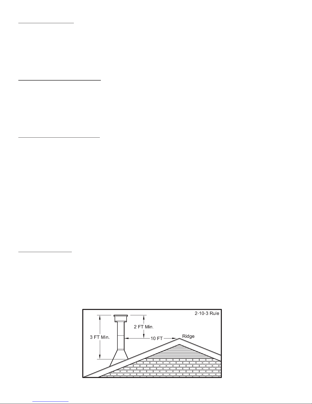
The following recommendations may be useful for the installation of your chimney:
• It must rise above the roof at least 3’ (0.9m) from the uppermost point of contact.
• The exterior portion should be double or triple wall pipe to ensure proper draft.
• The chimney must exceed any part of the building or other obstruction within a 10’ (3.04m) distance by a height of 2’ (0.6m).
• Installation of an interior chimney is always preferable to an exterior chimney. The interior chimney will be hotter than an
exterior chimney that is being cooled by the ambient air outside the house. Therefore the gas which circulates will cool slower,
thus reducing the build-up of creosote and the risk of chimney fi res.
• The draft caused by the tendency for hot air to rise will be increased with an interior chimney.
• Using a fi re screen at the extremity of the chimney requires regular inspection in order to insure that it is not obstructed thus
blocking the draft, and it should be cleaned when used regularly.
TYPE HT CHIMNEY
Your wood stove may be hooked up with a factory built or masonry chimney. If you are using a factory built chimney, it must
comply with UL 103 or CSA-B365 standard; therefore it must be a Type HT (2100°F). It is extremely important that it be installed
according to the manufacturer’s specifi cations.
If you are using a masonry chimney, it is important that it be built in compliance with the specifi cations of the National Building
Code. It must be lined with fi re clay bricks, metal or clay tiles sealed together with fi re cement. (Round fl ues are the most effi cient).
The interior diameter of the chimney fl ue must be 4”-6”. A fl ue which is too small may cause draft problems, while a large fl ue
favors rapid cooling of the gas, and hence the build-up of creosote and the risk of chimney fi res. Note that it is the chimney and not
the stove which creates the draft effect; your stove’s performance is directly dependent on an adequate draft from your chimney.
8
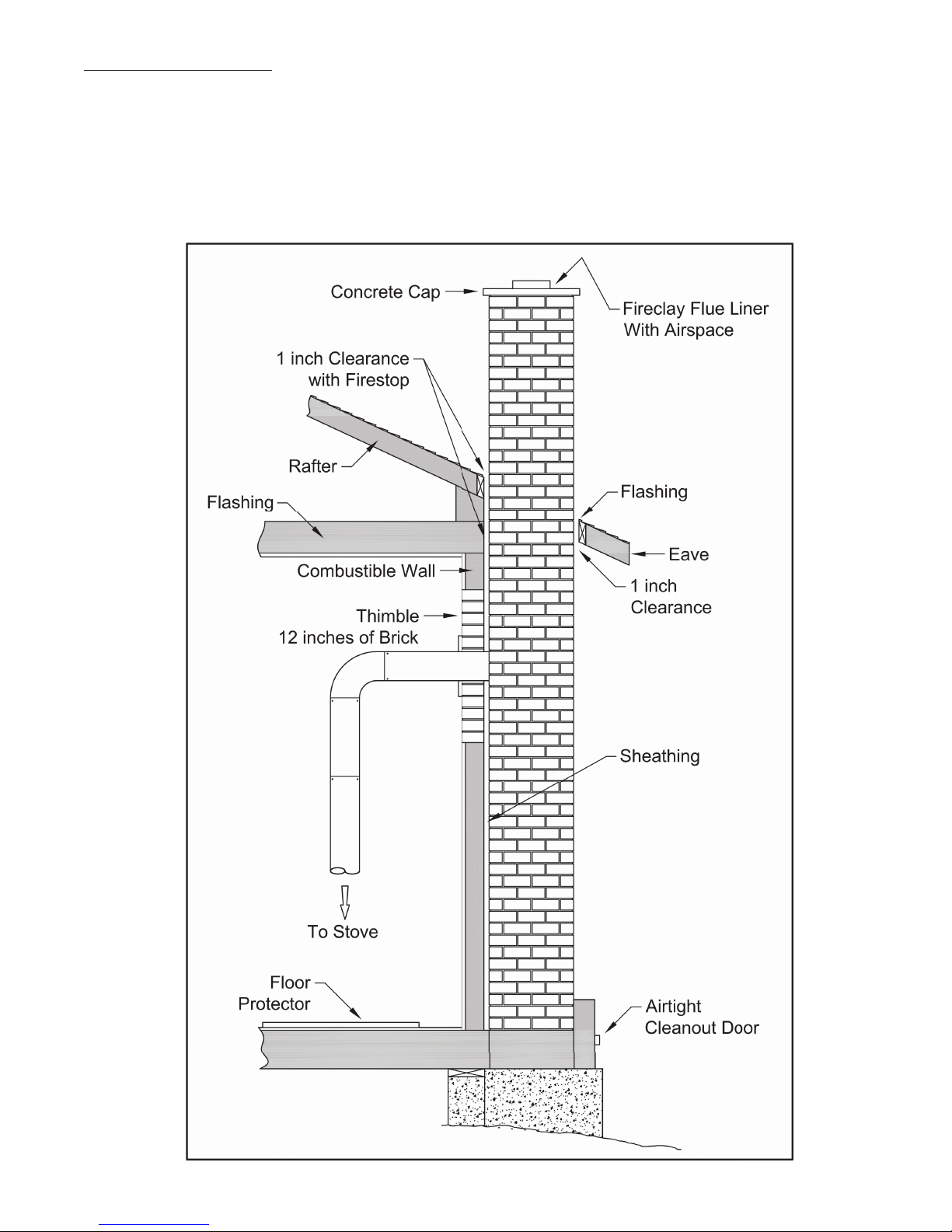
MASONRY CHIMNEY :
Ensure that a masonry chimney meets the minimum standards of the National Fire Protection Association (NFPA) by having it
inspected by a professional. Make sure there are no cracks, loose mortar or other signs of deterioration and blockage. Have the
chimney cleaned before the stove is installed and operated. When connecting the stove through a combustible wall to a masonry
chimney, special methods are needed as explained in the “Combustible Wall Chimney Connector Pass-Throughs” Section.
9
 Loading...