

Breckwell SP8500 Owner's Manual
UNITED STATES STOVE COMPANY
“Keeping North America Warm Since 1869”
MULTI-FUEL FURNACE MODEL SP8500
Approved for
US and Canadian use.
Safety tested and listed to UL
391-2010, ASTM E1509-04,
and CSA-B366.1-11
C
ertifi ed for installation in a
residential or mobile home as a
stand-alone or add-on furnace
(ductwork connection only).
Certified to comply with 2015 particulate emissions standards.
U.S. Environmental Protection Agency
Owner’s Manual
Please read this entire manual before installation and use of this appliance. Failure to follow
these instructions could result in property damage, bodily injury, or even death.
Contact your local building or fi re offi cials about restrictions and installation inspection
requirements in your area.
SAVE THESE INSTRUCTIONS.
The French version is available for download from the site Breckwell: http://www.breckwell.com/
La version française est disponible pour téléchargement à partir du site Breckwell: http://www.breckwell.com/
Breckwell
227 Industrial Park Road P.O. Box 151
South Pittsburg, TN 37380
(800) 750-2723 • www.breckwell.com
852014C-1909E

SAFETY PRECAUTIONS
Note: The BTU ratings mentioned above are based on
the EPA test protocol burning dimensional Douglas Fir
lumber. Our advertised BTU’s are based on the fi rst hour
of operation at high burn rate burning cordwood.
IMPORTANT: Read this entire manual before installing
and operating this product. Failure to do so may result
in property damage, bodily injury, or even death. Proper
installation of this furnace is crucial for safe and effi cient
operation.
Contact your local building offi cials to obtain a permit
and information on any additional installation restrictions
or inspection requirements in your area.
DO NOT throw this manual away. This manual has
important operation and maintenance instructions
that you will need at a later time. Always follow the
instructions in this manual.
Never try to repair or replace any part of the furnace
unless instructions for doing so are given in this manual.
All other work should be done by a trained technician.
Install appliance and venting at clearances specifi ed in
this manual.
DO NOT connect the pellet exhaust vent to a vent
serving any other appliance or furnace.
DO NOT install a fl ue damper in the exhaust venting
system of this unit.
Use of outside air is not required for this unit, but
is highly recommended. If installed into a tightly
constructed home, (Mobile Home) a fresh air opening of
at least 2 in. diameter (150mm) into the room where the
unit is installed is required. However return air make-up
is required for maximum heat distribution throughout
your home.
This heater is designed and approved as a multi-fuel
(corn or wood pellets) furnace. Use only dried shelled
corn with a moisture content of 11% or less (which
provides the best results). Pellet fuel used should have
an ash content of 1% or less. If not, performance and
effi ciency of the unit will suffer, and your warranty may
be voided.
Never use gasoline, gasoline-type lantern fuel, kerosene,
charcoal lighter fl uid, or similar liquids to start or ’freshen
up’ a fi re in this furnace. Keep all such liquids well away
from the furnace while it is in use.
A working smoke detector must be installed in the same
room as this product.
DO NOT unplug the furnace if you suspect a malfunction.
Turn the ON/OFF SWITCH to ”OFF’ and contact your
dealer.
Your furnace requires periodic maintenance and cleaning
(see ”MAINTENANCE ”). Failure to maintain your
furnace may lead to improper and/or unsafe operation.
DANGER: Risk of Fire or Explosion - DO NOT BURN
GARBAGE, GASOLINE, NAPTHA, ENGINE OIL, OR
OTHER INAPPROPRIATE MATERIALS.
Disconnect the power cord before performing any
maintenance! NOTE: Turning the ON/OFF Switch to
”OFF” does not disconnect all power to the electrical
components of the furnace.
Allow the furnace to cool before performing any
maintenance or cleaning. Ashes must be disposed
of in a steel container with a tight fi tting lid. The
closed container of ashes should be placed on a noncombustible surface or on the ground, well away from
all combustible materials, pending fi nal disposal.
The exhaust system should be checked monthly during
the burning season for any build-up of soot or creosote.
Creosote in your exhaust can potentially cause a
chimney fi re. In the event of a chimney fi re, contact
your fi re department immediately and press the “OFF”
button on your furnace. Have a clearly understood plan
to handle a chimney fi re.
CAUTION: Keep children away. Do not touch during
operation. Educate all children on the dangers of a
high-temperature furnace. Young children should be
supervised when they are in the same room as the
furnace.
A power surge protector is recommended. This unit
must be plugged into a 110 - 120V, 60 Hz grounded
electrical outlet. Do not use an adapter plug or sever
the grounding plug. Do not route the electrical cord
underneath, in front of, or over the furnace. Do not
route the cord in foot traffi c areas or pinch the cord
under furniture.
The furnace will not operate during a power outage. If a
power outage does occur, check the furnace for smoke
spillage and open a window if any smoke spills into the
room.
The feed door and ash pan must be closed and sealed
during operation to keep products of combustion from
escaping the furnace. Keep all seals in good condition.
Never block free fl ow of air through the open vents
of the unit.
Keep foreign objects out of the hopper.
The moving parts of this furnace are propelled by high
torque electric motors. Keep all body parts away from
the auger while the furnace is plugged into an electrical
outlet. These moving parts may begin to move at any
time while the furnace is plugged in.
Do not place clothing or other fl ammable items on or
near this furnace.
This appliance is not intended for commercial use.
WARNING: DO NOT INSTALL IN SLEEPING ROOM.
CAUTION: THE STRUCTURAL INTEGRITY OF
THE MANUFACTURED HOME FLOOR, WALL, AND
CEILING/ROOF MUST BE MAINTAINED.
2
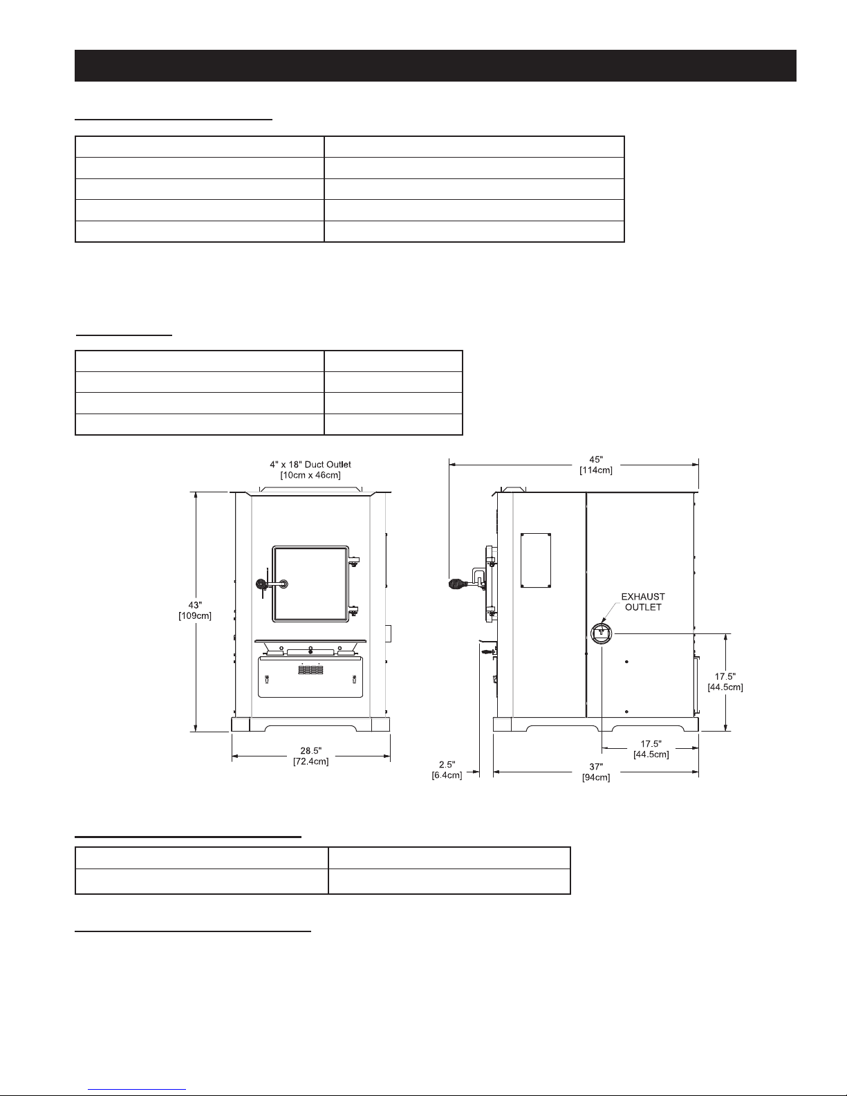
HEATING SPECIFICATIONS
SPECIFICATIONS
Input BTU/Hr
Heating Capacity
Fuel Burn Rate
1
2
3
50,000 to 105,000 BTU/hr.
1,200 - 2,800 sq. ft.
5.0 - 13.0 lbs./hr.
Burn Time (lowest setting) 70 hours continuous
Hopper Capacity 160 lbs
1
BTU output will vary depending on the quality and type of fuel. Use PFI listed fuels for the best results.
2
Heating capacity will vary depending on fl oor plan layout of your home, degree of insulation, and the outside temperature.
3
Fuel size may effect the actual rate of fuel feed and burn times. Fuel feed rates may vary by as much as 20%. Use PFI
listed fuel for best results.
DIMENSIONS
Height 43 in. [109cm]
Width 28-1/2 in. [72.4cm]
Depth 45 in. [114cm]
Weight 250 lbs.
ELECTRICAL SPECIFICATIONS
Electrical Rating
Watts (operational)
SAFETY AND EPA COMPLIANCE
Your Breckwell Furnace has been safety tested and listed to UL 391-2010, ASTM E1509-04, and CSA-B366.1-11, by
Intertek-Test Laboratories, Inc. Portland, Oregon USA. It is also exempt from EPA Phase II requirements.
3
110-120 volts, 60 HZ, 9.5 Amps
1150 (max. approx.)

FUEL CONSIDERATIONS
SHELLED CORN (DRY, PREFERABLY CORN WITH 11% OR LESS MOISTURE CONTENT)
• Optimum moisture content of corn should be 11% or less. Wet corn will rapidly deteriorate furnace components,
reduce effi ciency and void all warranties. Purchase a moisture tester if in doubt.
• Corn must be clean and free from debris. Never burn corn right from the fi eld. Damage caused by dirty corn is not
covered by the product warranty. Ask for clean fi ltered, bagged corn only. Stalk parts, excessive fi nes and cob
remnants will clog the auger.
• NEVER BURN SEED CORN IN YOUR FURNACE. Seed corn is treated with chemical pesticides that are harmful
or fatal if swallowed, therefore, seed corn is dangerous to have in the house, especially where children can reach it.
• Never burn “Deer Corn.” It frequently contains molasses/sugars.
• Store your corn supply in a dry place and keep bags or container sealed to prevent your corn from absorbing excess
moisture. Test the moisture content periodically to ensure proper dryness.
• There are many varieties of corn grown around the world. Each variety has unique characteristics including the
shape and size of the kernel. Your furnace will burn more consistently with a small to midsize kernel corn. If the
kernel size of the corn varies greatly or if you switch sources frequently, you will get a less consistent burn. Therefore, purchasing corn from the same source will help achieve a more consistent burn. DO NOT USE CORN WITH
A HIGH WAX CONTENT!
• Oyster shell is highly recommended for best burn operations and to reduce clinker build-up
WOOD PELLETS
• As with corn, be consistent with your pellet supplier. Pellets will vary in content and burn characteristics from supplier to supplier. A consistent supply of pellets will result in a more consistent and effi cient burn.
• Check your pellets for foreign objects. Your furnace warranty will not cover damage done to your furnace due to
foreign objects in the fuel supply.
• Store your pellets in a dry place to prevent them from absorbing added moisture.
• To decrease sawdust buildup, the hopper will need to be vacuumed out after every 6-8 bags of pellets or more often
if the pellets are poor quality. You may have to screen-sift each bag of pellets if sawdust becomes a problem.
• Wood Pellets vary in size and ash content from less than 1% to 3% or more. Your furnace will burn more effi ciently
with small to midsize pellets. Low ash content pellets will allow you to burn the furnace longer between cleanings.
Only wood pellets manufactured to the Pellet Fuel Industries (P.F.I.) standard for residential pellet fuels are recommended. Performance will suffer if nonstandard pellets are used. Consult your local Breckwell reseller for more
information on approved wood pellet fuel.
• If fans are used in the fuel storage area, they should be installed so as not to create a negative pressure in the room
where your furnace is located.
CAUTION: DO NOT PLACE SUCH FUELS WITHIN THE SPACE HEATER’S INSTALLATION
CLEARANCES OR WITHIN THE SPACE REQUIRED FOR REFUELING AND ASH REMOVAL.
The top down method of fi re building is recommended for this appliance. After making sure that the stove air intake
controls are fully open (completely pull-out towards you), Place the largest pieces of wood on the bottom, laid in parallel and close together. Smaller pieces are placed in a second layer, crossways to the fi rst. A third layer of still smaller
pieces is laid crossways to the second, this time with some spaces between. Then a fourth layer of loose, small kindling and twisted newspaper sheets tops off the pile.
Higher effi ciencies and lower emissions generally result when burning air dried seasoned hardwoods, as compared to
softwoods or to green or freshly cut hardwoods.
DO NOT BURN:
1. Garbage;
2. Lawn clippings or yard waste;
3. Materials containing rubber, including tires;
4. Materials containing plastic;
5. Waste petroleum products, paints or paint thinners,
or asphalt products;
6. Materials containing asbestos;
7. Construction or demolition debris;
8. Railroad ties or pressure-treated wood;
9. Manure or animal remains;
Burning these materials may result in release of toxic fumes or render the heater ineffective and cause smoke.
Dead wood lying on the forest fl oor should be considered wet, and requires full seasoning time. Standing dead wood
can usually be considered to be about 2/3 seasoned. Splitting and stacking wood before it is stored accelerates drying
time. Storing wood on an elevated surface from the ground and under a cover or covered area from rain or snow also
accelerates drying time. A good indicator if wood is ready to burn is to check the piece ends. If there are cracks radiating in all directions from the center then the wood should be dry enough to burn. If your wood sizzles in the fi re, even
though the surface is dry, it may not be fully cured, and should be seasoned longer.
10. Salt water driftwood or other previously salt water
saturated materials;
11. Unseasoned wood; or
12. Paper products, cardboard, plywood, or particleboard. The prohibition against burning these materials does not prohibit the use of fi re starters made
from paper, cardboard, saw dust, wax and similar
substances for the purpose of starting a fi re in an af-
fected wood heater.
4
INSTALLATION
INSTALLATION OPTIONS
Read this entire manual before you install and use your Multi-Fuel Furnace. Failure to follow instructions
may result in property damage, bodily injury, or even death!
(See specifi c installation details for clearances and other installation requirements)
Certifi ed for installation in a Residentail Type home in the USA and Canada. Also may be installed into a Manufactured
or Mobile Home.
As a Primary Furnace—the unit functions independently of any other system. The “Room Air” blowers will come on
when the plenum and exhaust temperatures reach a preset point programmed into the furnace’s circuit board (PCB). Unit
may also be used as a stand-alone shop heater. This is the only approved installation confi guration in which ductwork
or return air is not required. All other confi gurations utilizing a ductwork system must supply return air to the appliance.
As a Secondary (Add-On) Furnace—the unit aids an existing gas/electric furnace helping cut down on operation time.
It is recommended that only a authorized technician install your Multi-Fuel Furnace, preferably an NFI certifi ed specialist.
Canada requires that the installation of the pellet-fuel furnace shall comply with the applicable requirements of CSA-B365.
IMPROPER INSTALLATION: The manufacturer will not be held responsible for damage caused by the mal-
function of a furnace due to improper venting or installation. Call (800) 750-2723 and/or consult a professional
installer if you have any questions.
ADDITIONAL ITEMS REQUIRED FOR INSTALLATION
• UL listed 3 inch or 4 inch (Depending on application) “PL” pellet venting exhaust system.
• Air distribution duct work. Transition from 4.5 inch x 18.5 inch rectangle to 10 inch round is provided.
• Air fi lter (Optional). Size: 10 x 20 x 1
• Floor Protection (If not installed on a non-combustible fl oor)
• Fresh air for combustion: 2 inches[5cm] diameter - If installed in a manufactured / mobile home or located in a small,
tightly constructed room.
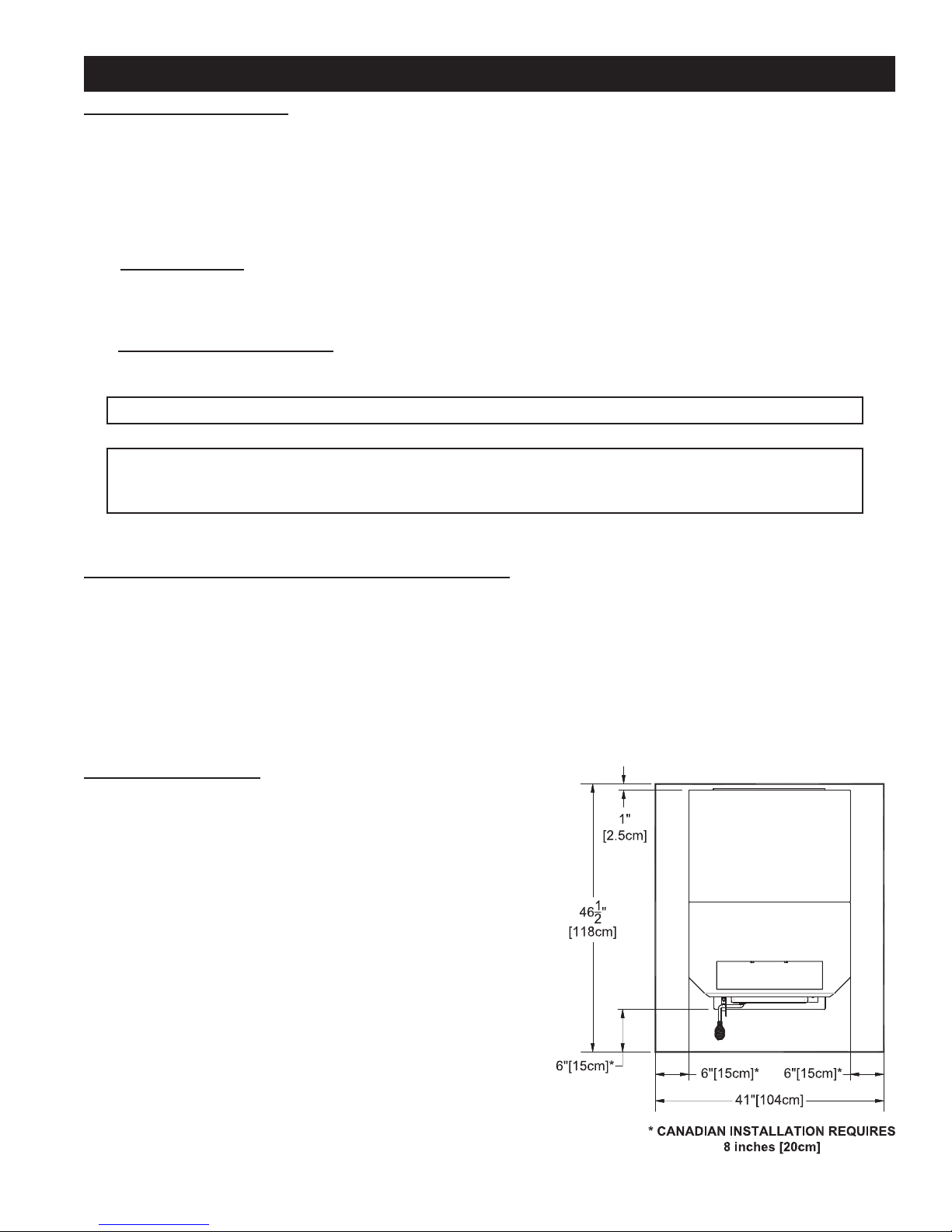
FLOOR PROTECTION
This unit must be installed on a non-combustible fl oor surface. If a
fl oor pad is used, it should be UL listed or equal. The fl oor pad or
non-combustible surface should be large enough to extend a minimum
of 6-inches in front, 6-inches on each side, and 1-inch behind the
furnace for horizontal termination.
Floor protection must extend under and 2-inches to each side of the
chimney tee for an interior vertical termination.
A 1 inch thick Floor Protector is recommended with installation.
5
INSTALLATION
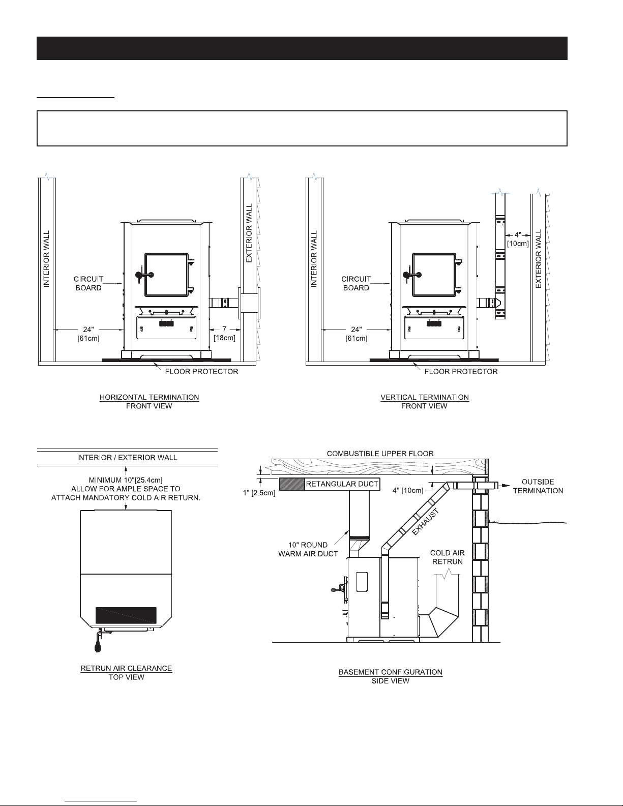
CLEARANCES
NOTE: Distance on the left-hand side of your Multi-Fuel Furnace is set at 24 inches for suitable access to
the control panel and for fuel loading. This distance may be less, but not less than 7 inches.
6

INSTALLATION
VENTING REQUIREMENTS
Install vent at clearances specifi ed by the vent manufacturer.
Do not connect the pellet vent to a vent serving any other appliance or furnace.
Do not install a fl ue damper in the exhaust venting system of this unit.
INSPECT EXHAUST VENTING (joints, seals, etc.) REGULARLY TO ENSURE THAT SMOKE AND FLUE GASES
ARE NOT DRAWN INTO AND CIRCULATED BY THE AIR CIRCULATION SYSTEM.
The following installation guidelines must be followed to ensure conformity with both the safety listing of this furnace
and to local building codes.
MAXIMUM VENTING DISTANCE
Installation MUST include at least 3-feet of vertical pipe. This will create a natural draft to reduce the possibility of smoke
or odor escaping during appliance shutdown and keep exhaust from causing a nuisance or hazard by exposing people
or shrubs to high temperatures. The maximum recommend vertical venting height is 12-feet for 3-inch type “PL” vent.
Total length of horizontal vent must not exceed 4-feet (this does not include the clean-out tee). Use no more than 180
degrees of elbows (two 90-degree elbows, or two 45-degree and one 90-degree elbow, etc.) to maintain adequate draft.
PELLET VENT TYPE
A UL listed 3-inch or 4-inch type “PL” pellet vent exhaust system must be used for installation and attached to the pipe
connector provided on the back of the furnace (use a 3-inch to 4-inch adapter for 4-inch pipe). Use 4-inch vent if the
vent height is over 12-feet or if the installation is over 2,500 feet above sea level.
We recommend the use of Simpson Dura-Vent® or Metal-Fab® pipe (if you use other pipe, consult your local building
codes and/or building inspectors). Do not use Type-B Gas Vent pipe or galvanized pipe with this unit. The pellet vent
pipe is designed to be disassembled for cleaning and should be checked several times during the burning season. Pellet
vent pipe is not furnished with the unit and must be purchased separately.
PELLET VENT INSTALLATION
The installation must include a clean-out tee to enable collection of fl y ash and to permit periodic cleaning of the exhaust
system. 90-degree elbows accumulate fl y ash and soot thereby reducing exhaust fl ow and performance of the furnace.
Each elbow or tee reduces draft potential by 30% to 50%.
All joints in the vent system must be fastened by at least 3 screws, and all joints must be sealed with HI-TEMP RTV
silicone sealant to be airtight. The area where the vent pipe penetrates to the exterior of the home must be sealed with
silicone or other means to maintain the vapor barrier between the exterior and the interior of the home.
Vent surfaces can get hot enough to cause burns if touched by children. Noncombustible shielding or guards may be
required.
PELLET VENT TERMINATION
Do not terminate the vent in an enclosed or semi-enclosed area, such as; carport, garage, attic, crawl space, under a
sun deck or porch, narrow walkway, or any other location that can build up a concentration of fumes.
The termination must exist above the outside air inlet elevation.
The termination must not be located where it could become plugged by snow or other materials.
IMPORTANCE OF PROPER DRAFT
Draft is the force which moves air from the appliance up through the chimney. The amount of draft in your chimney
depends on the length of the chimney, local geography, nearby obstructions and other factors. Too much draft may
cause excessive temperatures in the appliance. Inadequate draft may cause backpuffi ng into the room and ‘plugging’
of the chimney. “Inadequate draft will cause the appliance to leak smoke into the room through appliance and chimney
connector joints.”
“An uncontrollable burn or excessive temperature indicates excessive draft.”
Take into account the chimney’s location to insure it is not too close to neighbors or in a valley which may cause unhealthy
or nuisance conditions.
IMPORTANT! This unit is equipped with a negative draft system that pulls through the burn pot and pushes the exhaust out of the dwelling. If this unit is connected to a fl ue system other than the way explained in this manual, it will not
function properly.
7
INSTALLATION
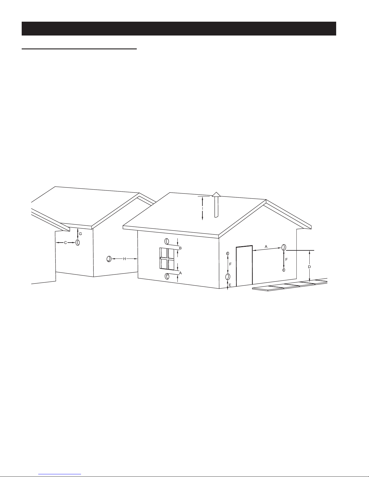
VENT TERMINATION CLEARANCES:
A) Minimum 4-foot (1.22m) clearance below or beside any door or window that opens.
B) Minimum 1-foot (0.3m) clearance above any door or window that opens.
C) Minimum 3-foot (0.91m) clearance from any adjacent building.
D) Minimum 7-foot (2.13m) clearance from any grade when adjacent to public walkways.
E) Minimum 2-foot (0.61m) clearance above any grass, plants, or other combustible materials.
F) Minimum 3-foot (0.91m) clearance from an forced air intake of any appliance.
G) Minimum 2-foot (0.61m) clearance below eves or overhang.
H) Minimum 1-foot (0.3m) clearance horizontally from combustible wall.
I) Must be a minimum of 3 foot (0.91m) above the roof and 2 foot (0.61m) above the highest point or the roof within
10 feet (3.05m).
8
VENT TERMINATION CLEARANCES
INSTALLATION
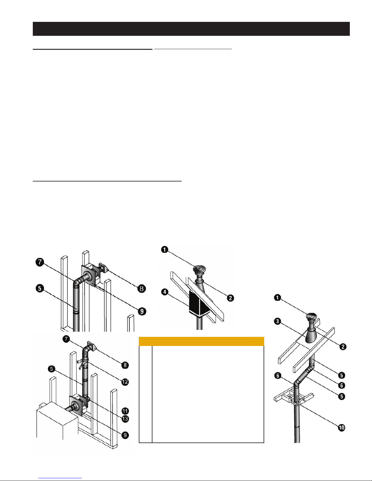
THROUGH THE WALL INSTALLATION (RECOMMENDED INSTALLATION)
To vent the unit through the wall, connect the pipe adapter to the exhaust motor adapter. If the exhaust adapter is at least
24-inches above ground level, a straight section of pellet vent pipe can be used through the wall.
Your furnace dealer should be able to provide you with an installation kit, which will
the proper clearance through a combustible wall. Once outside the structure, a 3-inch clearance should be maintained
from the outside wall and a clean out tee should be placed on the pipe with a 90-degree turn away from the house. At
this point, a 3-foot (minimum) vertical section of pipe should be added with a horizontal cap, which would complete the
installation.
A support bracket should be placed just below the termination cap or one every 4-feet to make the system more stable.
If you live in an area that has heavy snowfall, it is recommended that the installation be taller than 3-feet to get above the
snowdrift line. This same installation can be used if yo
section and vertical pipe inside until ground level is reached. With this installation you have to be aware of the snowdrift
line, dead grass, and leaves. We recommend a 3-foot minimum vertical rise on the inside or outside of the house.
The “through the wall” installation is the least expensive and simplest installation. Never terminate the end vent under a
deck, in an alcove, under a window, or between two windows. We recommend Simpson Dura-Vent® or Metal-Fab® kits.
ur furnace is below ground level by simply adding the clean-out
include a wall thimble that will allow
THROUGH THE ROOF/CEILING INSTALLATION
When venting the furnace through the ceiling, the pipe is connected in the same manner as a wall installation, except
the clean-out tee is always on the inside of the house, and a 3-inch adapter is placed in front of the clean-out tee.
You must use proper ceiling support fl anges and roof fl ashing (supplied by the pipe manufacturer; follow the pipe
manufacturer’s directions). It is important to note that if your vertical run of pipe is more than 15-feet, the pellet vent
pipe size should be increased to 4-inches in diameter.
Do not exceed more than 4-feet of pipe on a horizontal run and use as few elbows as possible. If an offset is required,
it is better to install 45-degree elbows rather than 90-degree elbows.
9
1 Vertical Cap
2 Storm Collar
3 Adjustable Roof Flashing
4 Cathedral Ceiling Support Box
5 Pipe
6 45° Elbow
7 90° Elbow
8 Horizontal Cap
9 Wall Thimble
10 Black Ceiling Support Firestop Spacer
11 Single Tee with Clean-Out Adapter
12 Tee Support Bracket
13 Double Tee with Clean-Out Adapter
 Loading...