

Breckwell P24I User Manual 2
TRADITION SERIES P24
P24FS P24I
• Warning: If your appliance is not properly installed a house fire may result. For your safety, follow
the installation directions. Contact local building or fire officials about restrictions and installation
inspection requirements in your area.
• PLEASE read this entire manual before installation and use of this pellet fuel-burning room heater.
Failure to follow these instructions could result in property damage, bodily injury, or even death.
• Save these instructions
OWNER’S MANUAL
PROFESSIONAL INSTALLATION IS HIGHLY RECOMMENDED
Manufactured by
Breckwell Hearth Products
Eugene, Oregon
Arlington, Texas
www.breckwell.com
©BRECKWELL HEARTH PRODUCTS
C-L-060 5/05

INTROD
UCTIO
Thank you for purchasing the Breckwell Pellet Burning Stove. You are now prepared to burn
wood in the most efficient, convenient way possible. To achieve the safest, most efficient and
most enjoyable performance from your stove, you must do three things: 1) Install it properly;
2) Operate it correctly; and 3) Maintain it regularly. The purpose of this manual is to help you
do all three.
PLEASE read this entire manual before installation and use of this pellet fuel-burning
room heater. Failure to follow these instructions could result in property damage,
bodily injury or even death.
Keep this manual handy for future reference.
Your Breckwell P24 comes as a fireplace insert or as a freestanding stove with a pedestal.
This stove has been independently tested to ASTM E1509-95 Standard Specification for
Room Heaters, Pellet Fuel Burning Type 1, UL 1482-1998 Standard for Solid Fuel Room
Heaters, Oregon Administrative Rules for Mobile Homes (814-23-900 through 814-23-909)
and Installation as a Stove Heater.
This pellet stove, when installed, must be electrically grounded in accordance with local
codes, or in the absence of local codes, with the National Electrical Code, ANSI/NFPA 70.
This appliance is designed specifically for use only with pelletized wood. It is designed for
residential installation according to current national and local building codes as a freestanding
room heater. It is also approved as a mobile home heater which is designed for connection to
an outside combustion air source.
The stove will not operate using natural draft or without a power source for the blower
systems and fuel feed system and must not be burned with any type of coal (see PROPER
FUEL).
This stove is designed to provide the optimum proportions of fuel and air to the fire in order to
burn free of smoke and soot. Any blockage of the air supply to or from the stove will seriously
degrade its performance and will be evidenced by a smoking exhaust and a sooting window.
For best operation the ash content of the pellet fuel should be less than 1% and the calorific
value approximately 8200 BTU/LB. Avoid high ash content fuels because this will rapidly fill
up the burn pot and eventually cut off the combustion air supply.
Commercial and industrial installations of Breckwell Pellet Stoves should not be used since
operational control is often not well managed in these settings.
Model: _____P24___________________
Style: ____________________________
Serial Number:_____________________
Purchase Date: ____________________
Purchased From:___________________
___________________
___________________
IMPORTANT INFORMATION
MAIL YOUR WARRANTY CARD TODAY
To receive full warranty coverage, you will
need to show evidence of the date you
purchased your stove. We suggest that
you attach your sales invoice to this page,
and fill in the form on the left, so that you
will have all the information you need in
one place should the need for service or
information occur.
N2
S
AFETY PRECAUTIONS
3
Do not operate your stove if you smell smoke
coming from it. Turn it off, monitor it, and call your
dealer.
Never use gasoline, gasoline-type lantern fuel,
kerosene, charcoal lighter fluid, or similar liquids to
start or “freshen up” a fire in this stove. Keep all
such liquids well away from the stove while in use.
Never block free airflow through the open vents of
the stove.
Never try to repair or replace any part of the
stove unless instructions are given in this
manual. All other work should be done by a
trained technician.
Do not throw this manual away. This manual
has important operating and maintenance
instructions that you will need at a later time.
Always follow the instructions in this manual.
Do not place clothing or other flammable
items on or near the stove.
Keep foreign objects out of the hopper.
The stove will not operate during a power outage.
If an outage does occur, check the stove for
smoke spillage and open a window if any smoke
spills into the room.
Disconnect the power cord before performing any
maintenance or repairs on the stove.
NOTE: Turning the stove “off” does not disconnect
all power from the stove.
During the start up period; 1) DO NOT open the
viewing door;
than ¾”;
by hand;
(unless you are priming the auger after running
out of pellets) as a dangerous condition could
result.
Do not unplug the stove if you suspect a
malfunction. Turn the stove off, periodically
inspect it, and call your dealer.
2) DO NOT open the damper more
3) DO NOT add pellets to the burnpot
4) DO NOT use the Fuel Feed button
The viewing door must be closed and latched
during operation.
Do not operate the stove if the flame
becomes dark and sooty or if the burnpot
overfills with pellets. Turn the stove off,
periodically inspect it, and call your dealer.
Hot while in operation. Keep children,
clothing, and furniture away. Contact may
cause skin burns. Educate all children of the
danger of a high temperature stove. Young
children should be supervised when they are
in the same room as the stove.
If the stove is installed in a room without air
conditioning, or in an area where direct
sunlight can shine on the unit, it is possible
this can cause the temperature of the stove to
rise to operational levels; one of the sensors
could then make the stove start on its own. It
is recommended that the stove be unplugged
when not in use for extended amounts of time
(i.e. during the summer months).
Contact your local building officials to obtain a
permit and information on any installation
restrictions or inspection requirements in your
area. Notify your insurance company of this stove
as well.
This unit must be properly installed to prevent the
possibility of a house fire. The instructions must be
strictly adhered to. Do not use makeshift methods
or compromise in the installation.
Your stove requires periodic maintenance and
cleaning. Failure to maintain your stove may lead
to smoke spillage in your home.
This stove must be connected to a standard 120
V., 60 Hz grounded electrical outlet. Do not use an
adapter plug or sever the grounding plug. Do not
route the electrical cord underneath, in front of, or
over the stove.
The exhaust system should be checked, at a
minimum, at least twice a year for any build up of
soot or creosote.
This is a pressurized exhaust system. We
suggest sealing all vent connector joints with
500°F (260°C) RTV silicone sealant to ensure
consistent performance and to avoid smoke
spillage. We also suggest that all horizontal
connector joints be sealed with UL-181-AP
foil tape.
Allow the stove to cool before carrying out
any maintenance or cleaning. Ashes must be
disposed in a metal container with a tight lid
and placed on a no combustible surface well
away from the home structure.
This stove is designed and approved for
pelletized wood fuel only. Any other type of
fuel burned in this heater will void the
warranty and safety listing.
When installed in a mobile home, the stove
must be bolted to the floor, have outside air,
and NOT BE INSTALLED IN A BEDROOM
(Per H.U.D. requirements). Check with local
building officials.
Breckwell Hearth Products grants no
warranty, implied or stated, for the
installation or maintenance of your stove,
and assumes no responsibility of any
consequential damage(s).

CO
S
4
TABLE OF
NTENT
INTRODUCTION --------------------------------------------------------------------------------------------- 2
SAFETY PRECAUTIONS ---------------------------------------------------------------------------------- 3
SPECIFICATIONS ------------------------------------------------------------------------------------------- 5
INSTALLATION --------------------------------------------------------------------------------------------- 5
Preparation ----------------------------------------------------------------------------------------- 5
Clearances ----------------------------------------------------------------------------------------- 5
Combustion Air Supply -------------------------------------------------------------------------- 6
When Outside Air Is Not Used ----------------------------------------------------------------- 6
Venting ----------------------------------------------------------------------------------------------- 6
Freestanding Installations ---------------------------------------------------------------------- 7
Insert Installations -------------------------------------------------------------------------------- 11
Electrical Installation ------------------------------------------------------------------------------ 14
Special Mobil Home Requirements ---------------------------------------------------------- 14
OPERATION --------------------------------------------------------------------------------------------------- 15
Proper Fuel ----------------------------------------------------------------------------------------- 15
Pre-Start-Up Check ------------------------------------------------------------------------------- 15
Building a Fire ------------------------------------------------------------------------------------- 15
The HotRod™ Automatic Fire Starter -------------------------------------------------------- 15
Panel Controls ------------------------------------------------------------------------------------- 15
Opening Door -------------------------------------------------------------------------------------- 16
Room Air Fan -------------------------------------------------------------------------------------- 16
Re-Starting a Warm Stove ---------------------------------------------------------------------- 16
If Stove Runs Out Of Pellets -------------------------------------------------------------------- 17
Damper Control ------------------------------------------------------------------------------------ 17
Refueling --------------------------------------------------------------------------------------------- 17
Breckwell Maintenance Tool -------------------------------------------------------------------- 17
Shutdown Procedure ----------------------------------------------------------------------------- 17
Safety Features ------------------------------------------------------------------------------------ 17
Optional Thermostat ------------------------------------------------------------------------------ 18
Thermostat Installation -------------------------------------------------------------------------- 18
(Please Read This) Operating Safety Precautions -------------------------------------- 19
MAINTENANCE ---------------------------------------------------------------------------------------------- 20
Ash Removal ---------------------------------------------------------------------------------------- 20
Ash Disposal - Freestanding ------------------------------------------------------------------- 20
Ash Disposal - Insert ------------------------------------------------------------------------------ 20
Vacuum Use ---------------------------------------------------------------------------------------- 21
Cleaning ---------------------------------------------------------------------------------------------- 21
Blowers ---------------------------------------------------------------------------------------------- 21
Chimney Cleaning -------------------------------------------------------------------------------- 22
Recommended Maintenance Schedule ----------------------------------------------------- 22
Removal & Replacement of Broken Door Glass ------------------------------------------ 22
TROUBLE SHOOTING GUIDE -------------------------------- ---------------- ---------------- ---------- 24
Smoke Smell or Soot Build-Up ---------------------------------------------------------------- 29
ELECTRICAL DIAGRAM --------------------------------------------------------------------------------- 30
REPLACEMENT PARTS LIST -------------------------------------------------------------------------- 31
WARRANTY ------------------------------------------------------------------------------------------------------ 32
INSTALLATION
5
SPECIFICATIONS
FREESTANDING:
Width: 26”
Height: 33 ¼”
Depth: 30 7/8” (excluding ash lip)
Weight: 325 lbs.
Flue size: 3” or 4”
Hopper Capacity: Up to 65 lbs.
(this can vary widely depending on pellet size, length, and diameter)
EPA status: exempt
Burn time: 1 lb. to 5 lbs. per hour
BTU range: 8,200 to 50,000
Approved installations: mobile home, alcove, conventional
FIREPLACE INSERT:
Width: 22” (at fireplace rear)
29 ½” (at fireplace opening)
Height: 21” (in fireplace)
Depth: 23 ½” (total)
16 3/8” (in fireplace)
Flashing Size: 44 ½” W x 28” H (medium)
48 ½” W x 32” H (large)
Weight: 250 lbs.
Flashing: 13 lbs.
Flue size: 3” or 4”
Hopper Capacity: Up to 70 lbs.
(this can vary widely depending on pellet size, length, and diameter)
EPA status: exempt
Burn time: 1 lb. to 5 lbs. per hour
BTU range: 8,200 to 50,000
Approved installations: zero-clearance, masonry, as a built-in
PREPARATION
Factory packaging must be removed, and some minor assembly work is required
prior to installation. Access to the rear of the stove is necessary.
The circuit board/control panel must be unpacked and installed in the side
flashing on the insert. (See installation instructions provided with the circuit
board)
NOTE: Normally, your dealer will perform these functions.
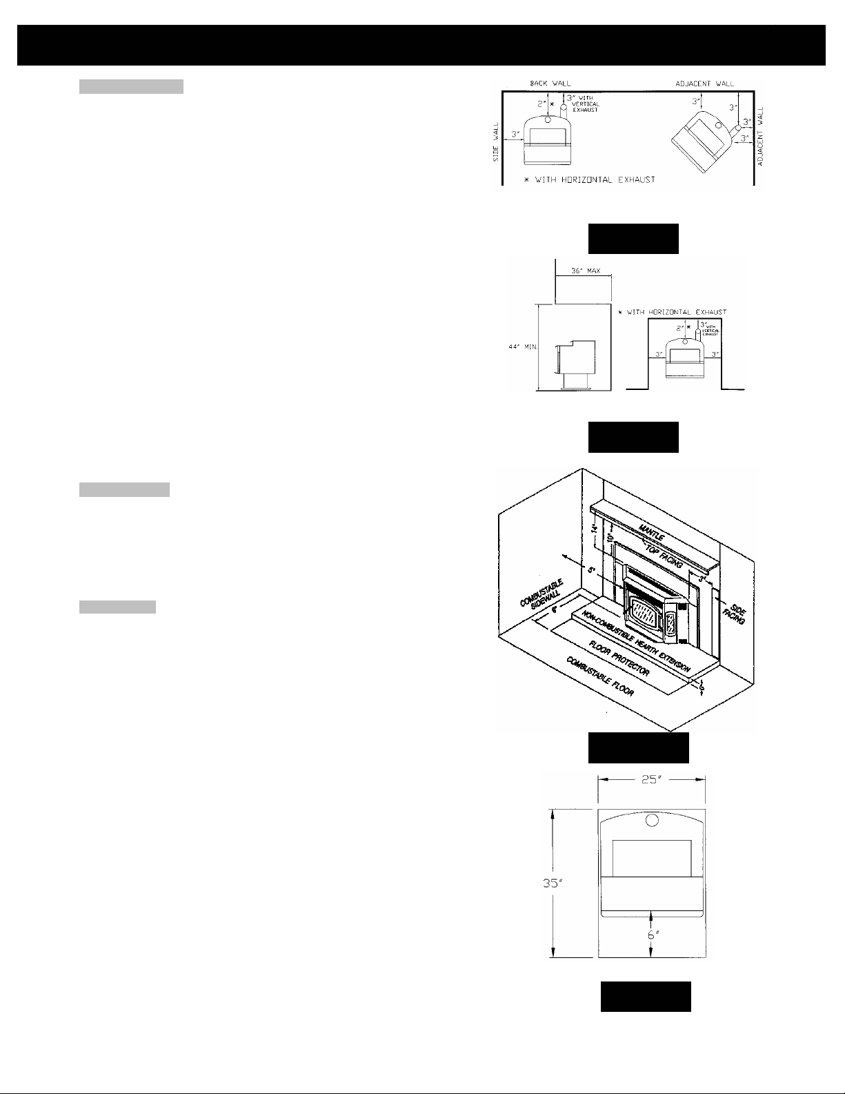
CLEARANCES
The Breckwell P24 Freestanding has been tested and listed for installation in
residential, mobile home and alcove applications.
The P24 Insert is approved for installation into code complying masonry
fireplaces.
The P24 Insert is also approved for use in listed factory built fireplaces (UL 127)
and standard residential built-ins (see As A Built-In Fireplace), including Mobile
Home built-in installations, of the following description: all brands at least 36”
wide and 20” high.
FLOOR PROTECTION: Freestanding installations, minimum 25” wide by 35”
deep. The stove must be placed on a continuous (grouted joints)
noncombustible material such as ceramic tile, cement board, brick, 3/8”
millboard or equivalent, or other approved or listed material suited for floor
protection.
THE MATERIAL(S) USED MUST HAVE, OR COMBINE TO HAVE, A MINIMUM
INSULATIVE RATING OF ‘R1’.
NOTE: ceramic tile, or any tile, requires a continuous sheet beneath to prevent
the possibility of embers falling through to the combustible floor if cracks or
separation should occur in the finished surface, this would include floor
protection for Built-in raised hearths. Check local codes for approved
alternatives.
Clearances are measured from the sides, back and face (door opening) or stove
body (refer to fig. 4).
DO NOT USE MAKESHIFT MATERIALS OR COMPROMISES IN THE
INSTALLATION OF THIS UNIT.
INSTALL VENT WITH CLEARANCES SPECIFIED BY THE VENT
MANUFACTURER.
SIDEWALL CLEARANCES
ALCOVE CLEARANCES
FLOOR PROTECTION
FIGURE 1
FIGURE 2
FIGURE 3
FIGURE 4
6
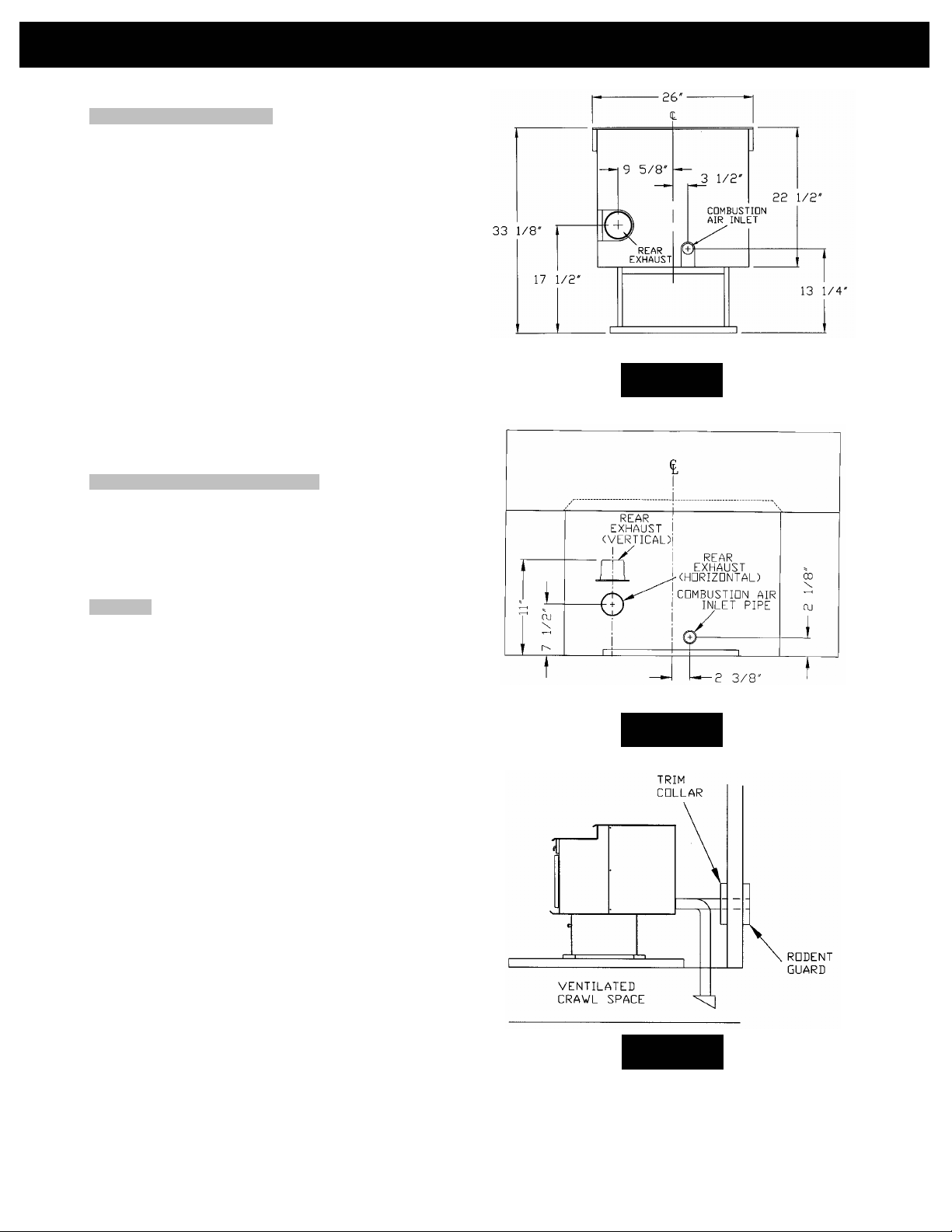
COMBUSTION AIR SUPPLY
For a mobile home installation the stove must be connected to an
outside source of combustion air. A 2” inside diameter metallic pipe,
either flexible or rigid, may be attached to the inlet at the stove’s rear
(refer to figures 5 & 6). A rodent guard (minimum ¼” wire
mesh)/wind hood must be used at the terminus (refer to figure 7). All
connections must be secured and airtight by either using the
appropriately sized hose clamp and/or UL-181-AP foil tape.
For mobile home installations only: 2” inside diameter pipe may
be used for the first 5 feet of combustion air supply run. From 5 to 10
feet use 2 ¾” inside diameter pipe. No combustion air supply may
exceed 10 feet.
Sources of Outside Combustion Air
a. In fireplaces
• Chimney top.
• Ash clean out door.
b. For freestanding installations
• A hole in floor near stove rear terminating only in a
ventilated crawl space.
• A hole in the wall behind the stove.
WHEN OUTSIDE AIR IS NOT USED
INSTALLATION
REAR VIEW P24FSA
FIGURE 5
If outside air is not used, it is important that combustion air is easily
available to the air inlet. A closeable outside air register can be used
in tightly insulated homes. In insert installations, flashing vents
should not be restricted. The flashing should not necessarily seal the
fireplace face.
VENTING
The Breckwell P4000 Vermont is certified for use with listed TYPE LVent, 3” or 4” diameter in size. The stove was tested with Simpson
Duravent brand. Class “A” chimney is not required. Refer to the
instructions provided by the vent manufacturer, especially when
passing through a wall, ceiling or roof.
This is a pressurized exhaust system. We suggest sealing all vent
connector joints with 500°F (260°C) RTV silicone sealant to ensure
consistent performance and to avoid smoke spillage. We also
suggest that all horizontal connector joints be sealed with UL-181AP foil tape.
FOLLOW L-VENT CHIMNEY MANUFACTURER’S
INSTALLATION INSTRUCTIONS.
DO NOT CONNECT THIS UNIT TO A CHIMNEY FLUE SERVING
ANOTHER APPLIANCE.
DO NOT INSTALL A FLUE DAMPER IN THE EXHAUST VENTING
SYSTEM OF THIS UNIT.
INSTALL VENT AT CLEARANCES SPECIFIED BY THE VENT
MANUFACTURER.
REAR VIEW P24I
FIGURE 6
FIGURE 7
INSTALLATION
7
Equivalent Vent Length (EVL)
The longer the run of pipe in your installation (both with insert and
freestanding), the more restriction there is in the system. Therefore,
larger diameter pipe should be used.
• Use 4” pipe if you have more than 15 feet of equivalent vent
length.
• Horizontal runs shall not exceed 10’ of EVL.
• Recommended vertical runs to be minimum of 8’.
• To calculate EVL, use the following conversions:
90º elbow or “T” = 5 equivalent feet
45º elbow = 3 equivalent feet
Horizontal Pipe Run = 1 equivalent foot per actual foot
Vertical Pipe Run = 0.5 equivalent foot per actual foot
NOTE: At altitudes above 3,000 feet, we suggest the use of 4”
diameter vent at an EVL of 7 feet or more.
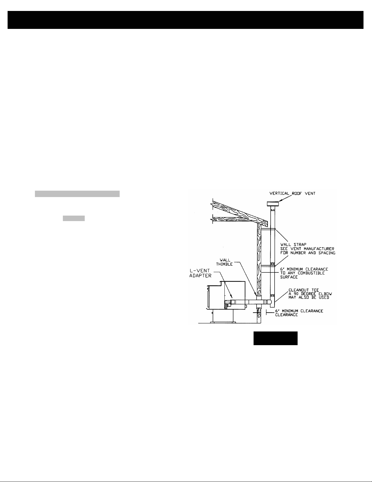
FREESTANDING INSTALLATION
A. HORIZONTALLY THROUGH WALL (refer to Figure 8)
NOTE: See “VENTING” and follow L-Vent chimney manufacturer’s
instructions.
1. Position stove, adhering to clearances shown in Figures 1 & 2.
2. Locate position of hole in wall; directly behind stove exhaust
vent (refer to figure 5).
3. Always maintain 3” clearance from combustible materials.
4. Install L-Vent wall thimble per L-Vent manufacturer’s
instructions.
5. Attach enough piping to penetrate and extend at least 6”
beyond exterior walls. An 8-foot vertical pipe run is suggested
where possible to reduce the possibility of smoke spillage in the
event of a loss of negative pressure.
6. Attach cap and seal outside wall thimbles with non-hardening
waterproof mastic.
7. Termination should not be located so that hot exhaust gases
can ignite trees, shrubs, or grasses or be a hazard to children.
Exhaust gases can reach temperatures of 500ºF and cause
serious burns if touched.
FIGURE 8
Locate terminations: a) not less than 3 feet above any
forced air inlet located within 10 feet; b) not less than 4
feet below or horizontally from, or one foot above, any
door, window or gravity air inlet into any building; c) not
less than two feet from an adjacent building and not
less than 7 feet above grade when located adjacent to
a public walkway. Mobile home installations must use
a spark arrester.
8
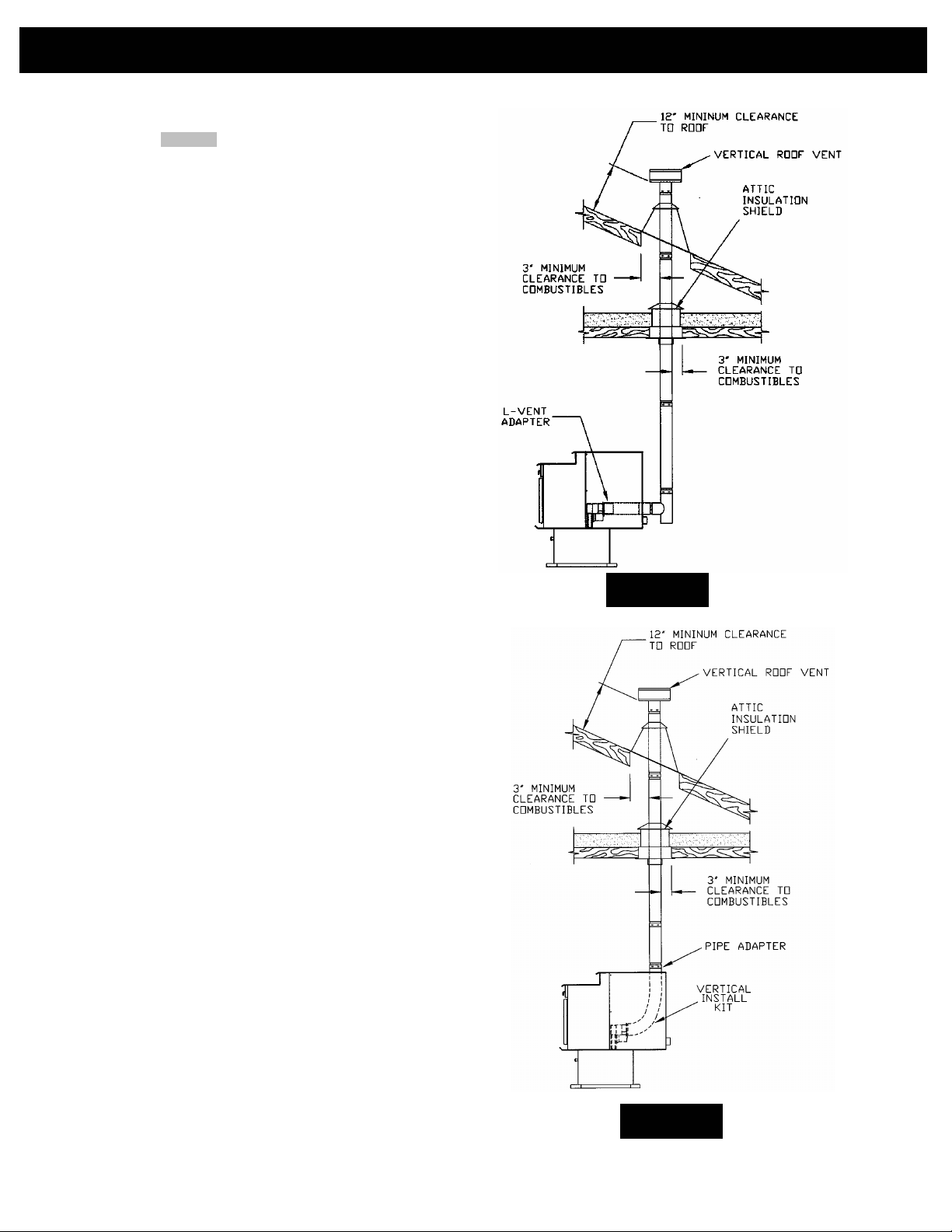
B. VERTICALLY WITH NEW CHIMNEY SYSTEM (Refer to
Figure 9a & 9b)
NOTE: See “VENTING” and follow L-Vent chimney manufacturer’s
instructions.
OPTION: To achieve a center vertical installation a 45º elbow and a
clean-out tee can be used to offset the pipe from the exhaust outlet
to the rear center of the stove (see figure 9a). You can also use the
P24FS Vertical Install Kit (part # A-VIK) (see figure 9b).
OPTION: Install L-Vent elbow in place of clean-out tee. Locate
stove. Drop plumb bob to center of tee outlet, mark point on ceiling.
Install ceiling support and L-Vent pipe per L-Vent manufacturer’s
instructions.
1. Always maintain 3” clearance from combustible materials.
When passing through additional floors or ceilings, always
install firestop spacer.
2. After lining up for hole in roof, cut either around or square hole
in roof, always 3” larger all the way around pipe. Install upper
edge and sides of flashing under roofing materials, nail to the
roof along upper edge. Do not nail lower edge. Seal nail heads
with non-hardening waterproof mastic.
3. Apply non-hardening, waterproof mastic where the storm collar
will meet the vent and flashing. Slide storm collar down until it
sits on the flashing. Seal and install cap. Mobile home
installations must use a spark arrester.
INSTALLATION
FIGURE 9a
FIGURE 9b
INSTALLATION
9
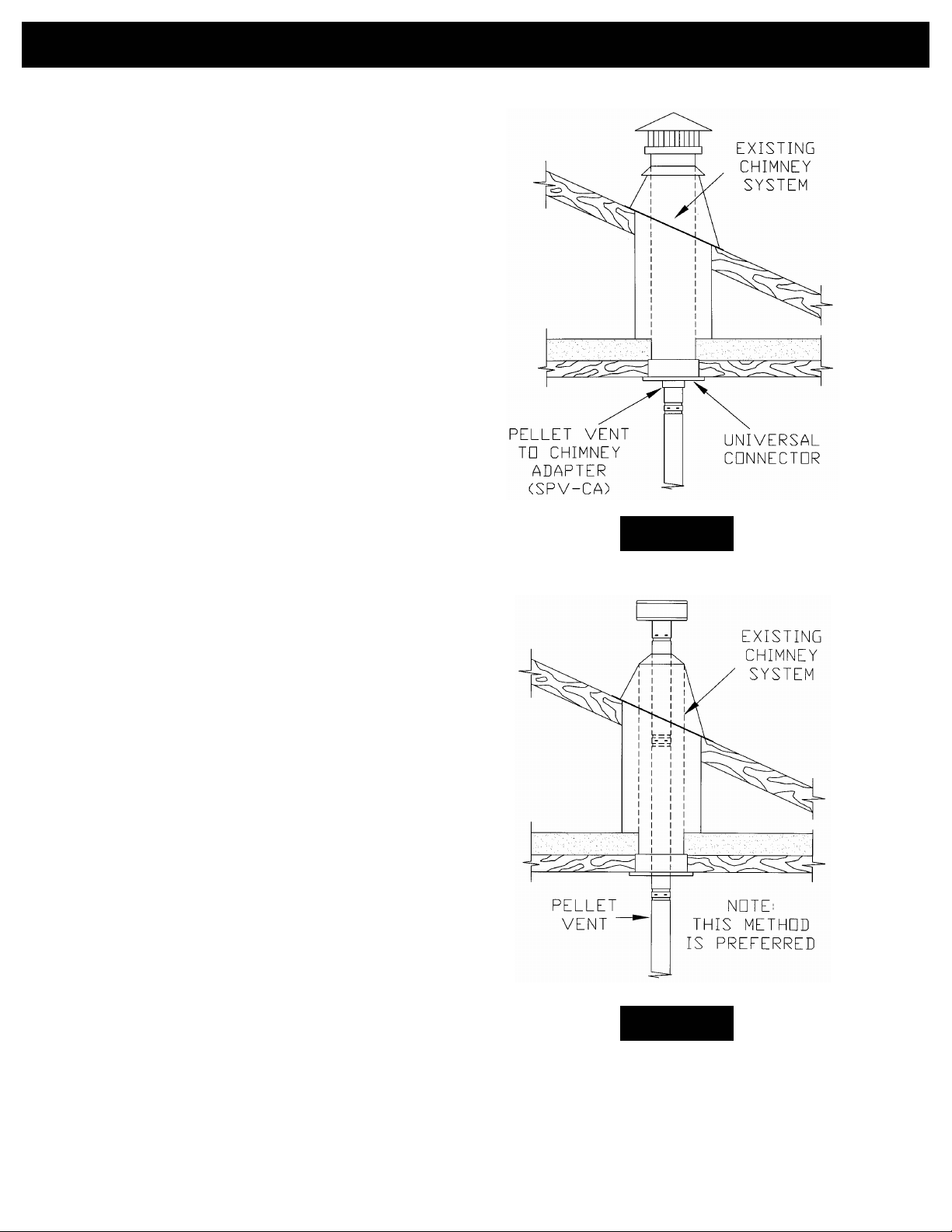
C. VERTICALLY INTO EXISTING CHIMNEY SYSTEM
Adapters are available to adapt from 3” L-Vent to 6” or 8” Class-A
chimney. (Figure 10a)
As an alternative, 3” or 4” L-Vent can be run inside existing chimney
to termination. (Figure 10b)
This is the preferred method.
Follow guidelines for equivalent vent length.
FIGURE 10a
FIGURE 10b
INSTALLATION10
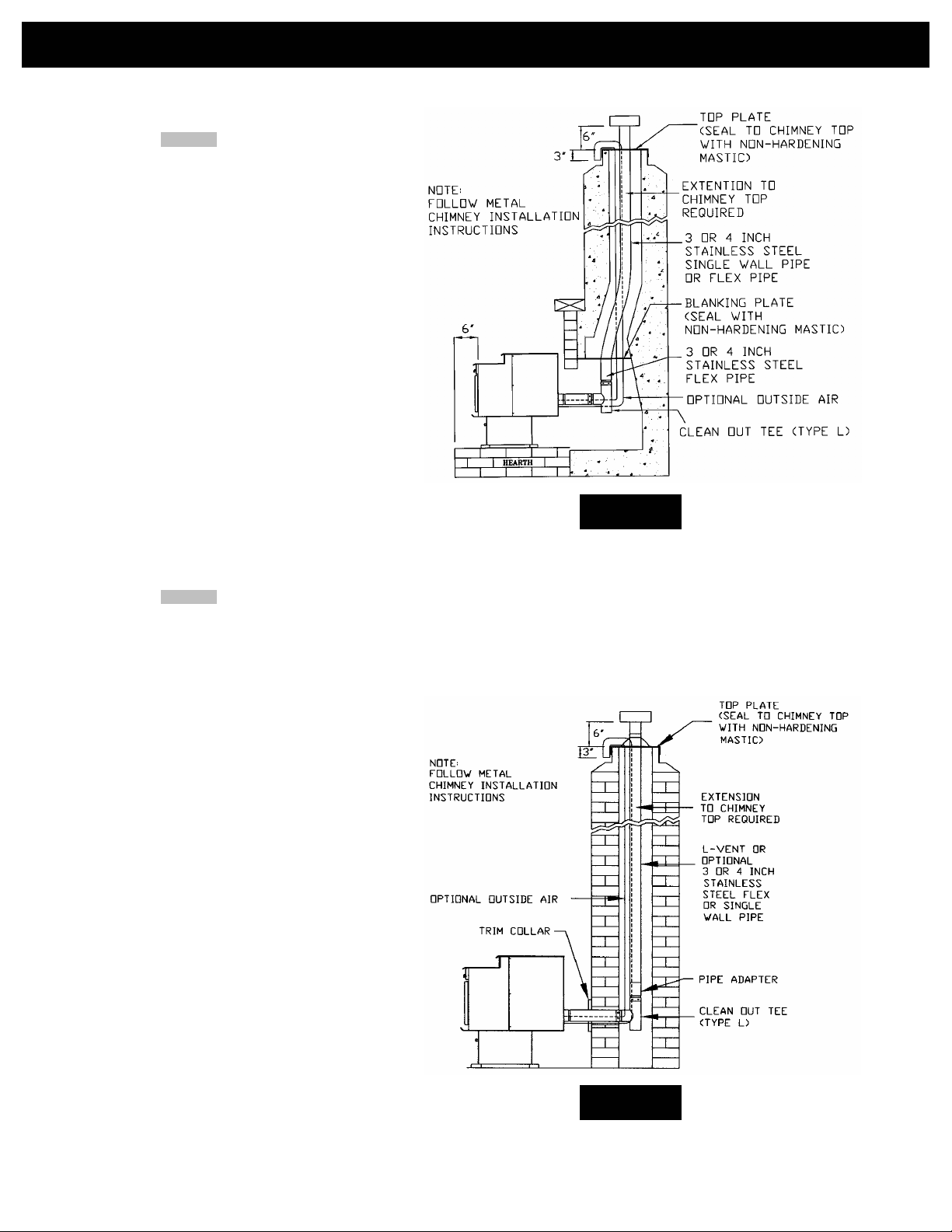
D. VERTICALLY INTO EXISTING MASONRY
FIREPLACE
NOTE: See “VENTING” and follow L-Vent chimney
manufacturer’s instructions.
1. Have the masonry chimney inspected by a qualified
chimney sweep or installer to determine its structural
condition.
2. You will need a pipe length equal to the chimney
height from the hearth. If outside combustion air is to
be used, you will need a pipe length equal to the
chimney height plus 18 inches.
3. Install a blanking plate and the chimney pipe, and if
used the outside air pipe, as shown in Figure 11.
4. Attach the L-Vent adapter, a section of pipe and
clean out tee, making sure the clean out tee is
centered in the chimney flue area. Use RTV,
metallic tape, and a minimum of three self-taping
screws at all joint connections to ensure a tight seal.
5. Position the stove, adhering to the clearances in
Figures 1 & 2.
6. Measure and build chimney top plate. Cut out holes
for chimney pipe, and if used the outside air pipe.
Install and seal with non-hardening mastic to
prevent water leakage. Install vent cap.
E. INSTALLATION THROUGH SIDE OF MASONRY
CHIMNEY
NOTE: See “VENTING” and follow L-Vent chimney
manufacturer’s instructions.
1. Position the stove, adhering to the clearances in
Figures 1 & 2. Mark the center of the hole where the
pipe is to pierce the masonry chimney.
2. It will be necessary to break out the masonry around
the location of the pipe center mark. Use a 4-inch
diameter hole for 3-inch pipe and 5-inch diameter
hole for 4-inch pipe.
3. Measure and build chimney top plate. Cut out holes
for chimney pipe, and if used the outside air pipe.
4. Install the tee on the bottom of the vertical pipe
system and lower it down the chimney until the
center branch of the tee is level with the center of
the hole in the masonry, as shown in Figure 12.
5. Install and seal the top plate from step 3 with nonhardening mastic. Slip the storm collar over the pipe,
and while holding the pipe at the proper elevation,
affix the collar with a minimum of three ¼” stainless
steel sheet metal screws. Seal all joints and seams
around the collar.
6. Connect the horizontal pipe by pushing it through
the hole in the masonry and lining it up with the
branch in the tee. Push the pipe into the tee while
twisting it to lock it into the tee.
7. If desired, once the horizontal pipe is in place, the
space between the pipe and masonry may be filled
with high-temperature grout.
8. Install the trim collar. An adjustable pipe length and
adapter may be needed to finish the connection to
the stove.
FIGURE 11
FIGURE 12
 Loading...