

Breckwell LUXURY SERIES SP2700, Classic Cast SPC4000, sp23 Owner's Manual
LUXURY SERIES SP2700
OWNER’S MANUAL
•
WARNING: IF YOUR APPLIANCE IS NOT PROPERLY INSTALLED A HOUSE FIRE MAY RESULT. FOR YOUR SAFETY, FOLLOW THE INSTALLATION DIRECTIONS. CONTACT LOCAL
BUILDING OR FIRE OFFICIALS ABOUT RESTRICTIONS AND INSTALLATION INSPECTION
REQUIREMENTS IN YOUR AREA.
• PLEASE read this entire manual before installation and use of this pellet fuel-burning
room heater. Failure to follow these instructions could result in property damage, bodily
injury, or even death.
• Save these instructions.
PROFESSIONAL INSTALLATION IS HIGHLY RECOMMENDED
This unit is not intended to be used as a primary source of heat.
French version is available for download from the U. S. Stove website: http://www.breckwell.com
Version française est disponible pour téléchargement à partir du site Web de la Poêle US: http://www.breckwell.com
Certified to comply with 2015 particulate emissions standards.
U.S. Environmental Protection Agency
Breckwell
227 Industrial Park Road P.O. Box 151
South Pittsburg, TN 37380
(800) 750-2723 • www.breckwell.com
©BRECKWELL HEARTH PRODUCTS
10/2013
852189C-1904E

INTRODUCTION
INTRODUCTION
This manual describes the installation and operation of the Breckwell, SP2700 wood heater. This heater meets the 2015
U.S. Environmental Protection Agency's crib wood emission limits for wood heaters sold after May 15, 2015. Under specifi c
test conditions this heater has been shown to deliver heat at rates ranging from 6,569 to 34,785 Btu/hr.”
Thank you for purchasing the Breckwell Pellet Burning Stove, you are now prepared to burn wood in the most effi cient,
convenient way possible. To achieve the safest, most effi cient and most enjoyable performance from your stove, you must
do three things: 1) Install it properly; 2) Operate it correctly; and 3) Maintain it regularly. The purpose of this manual is to
help you do all three.
PLEASE read this entire manual before installation and use of this pellet fuel-burning room heater. Failure to follow
these instructions could result in property damage, bodily injury or even death.
Keep this manual handy for future reference.
This stove has been independently tested to ASTM E1509-12 Standard Specifi cation for Room Heaters, Pellet Fuel Burning
Type 1, ULC-S627 Standard for Solid Fuel Room Heaters, ULC-S628 and Oregon Administrative Rules for Mobile Homes
(814-23-900 through 814-23-909) and Installation as a Stove Heater.
This pellet stove, when installed, must be electrically grounded in accordance with local codes, or in the absence of local
codes, with the National Electrical Code, ANSI/NFPA 70.
The authority having jurisdiction (such as municipal building department, fi re department, fi re prevention bureau,
etc.) should be consulted before installation to determine the need to obtain a permit.
This appliance is designed specifi cally for use only with pelletized wood. It is designed for residential installation according
to current national and local building codes as a freestanding room heater. It is also approved as a mobile home heater
which is designed for connection to an outside combustion air source.
The stove will not operate using natural draft or without a power source for the blower systems and fuel feed system and
must not be burned with any type of coal (see PROPER FUEL).
This stove is designed to provide the optimum proportions of fuel and air to the fi re in order to burn free of smoke and soot.
Any blockage of the air supply to or from the stove will seriously degrade its performance and will be evidenced by a smoking exhaust and a sooting window. For best operation the ash content of the pellet fuel should be less than 1% and the
calorifi c value approximately 8200 BTU/LB. Avoid high ash content fuels because this will rapidly fi ll up the burn pot and
eventually cut off the combustion air supply.
Commercial and industrial installations of Breckwell Pellet Stoves should not be used since operational control is often not
well managed in these settings.
IMPORTANT INFORMATION
MAIL YOUR WARRANTY CARD TODAY
To receive full warranty coverage, you will need
Model: _______________________
Style: _________________________
Serial Number: _________________
Purchase Date: _________________
Purchased From: _______________
to show evidence of the date you purchased
your stove. We suggest that you attach your
sales invoice to this page, and fi ll in the form
on the left, so that you will have all the information you need in one place should the need for
service or information occur.
2

WARRANTY INFORMATION CARD
Name__________________________________________ Telephone #: (_____)_____________
City____________________________________________ State_______ Zip_________________
Email Address __________________________________________________________________
Model # of Unit________________________________ Serial #___________________________
Fuel Type:
Wood Coal Pellet Gas Other _________________________
Place of Purchase (Retailer)______________________________________________________
City____________________________________________ State_______ Zip_________________
If internet purchase, please list website address___________________________________
Date of Purchase _______________________________________________________________
Reason for Purchase: Alternative Heat Main Heat Source
Decoration Cost Other _________________________
What was the determining factor for purchasing your new appliance?_______
I have read the owner’s manual that accompanies this unit and fully understand the:
Installation
Operation and Maintenance of my new appliance.
Print Name Signature Date
Please attach a copy of your purchase receipt.
Warranty not valid without a Proof of Purchase.
Warranty information must be received within 30 days of original purchase.
Detach this page from this manual, fold in half with this page to the inside and tape together. Apply a
stamp and mail to the address provided. You may use an envelope if you choose.
You may register online by going to www.breckwell.com
All information submitted will be kept strictly con dential. Information provided will not be sold for advertising purposes.
Contact information will be used solely for the purpose of product noti cations.
CUT HERE CUT HERE

Fold Here
Fold Here
PLACE
STAMP
HERE
United States Stove Company
P.O. Box 151
South Pittsburg, TN 37380
CUT HERE CUT HERE
Ԧ
Ԧ
Ԧ
Ԧ
Ԧ
Ԧ
Ԧ
Ԧ
Ԧ
Ԧ
Ԧ
Ԧ
Ԧ
Ԧ
Ԧ
SAFETY PRECAUTIONS
SAFETY PRECAUTIONS
Do not operate your stove if you smell smoke coming from it. Turn it off, monitor it, and call your
dealer.
Never use gasoline, gasoline-type lantern fuel,
kerosene, charcoal lighter fl uid, or similar liquids
to start or “freshen up” a fi re in this stove. Keep all
such liquids well away from the stove while in use.
Never block free airfl ow through the open vents of
the stove.
Keep foreign objects out of the hopper.
The stove will not operate during a power outage.
If an outage does occur, check the stove for smoke
spillage and open a window if any smoke spills into
the room.
Disconnect the power cord before performing any
maintenance or repairs on the stove.
NOTE: Turning the stove “off” does not disconnect
all power from the stove.
During the start up period; 1) DO NOT open the
viewing door; 2) DO NOT open the damper more
than ¼”; 3) DO NOT add pellets to the burnpot by
hand; 4) DO NOT use the Fuel Feed button (un-
less you are
pellets) as a dangerous condition could result.
Do not unplug the stove if you suspect a malfunction. Turn the stove off, periodically inspect it, and
call your dealer.
priming the auger after running out of
Never try to repair or replace any part of the stove
unless instructions are given in this manual. All other
work should be done by a trained technician.
Do not throw this manual away. This manual has
important operating and maintenance instructions
that you will need at a later time. Always follow the
instructions in this manual.
Do not place clothing or other fl ammable items on or
near the stove.
The viewing door must be closed and latched during
operation.
Do not operate the stove if the fl ame becomes dark
and sooty or if the burnpot overfi lls with pellets. Turn
the stove off, periodically inspect it, and call your
dealer.
Hot while in operation. Keep children, clothing, and
furniture away. Contact may cause skin burns. Educate all children of the danger of a high temperature
stove. Young children should be supervised when
they are in the same room as the stove.
If the stove is installed in a room without air conditioning, or in an area where direct sunlight can shine
on the unit, it is possible this can cause the temperature of the stove to rise to operational levels; one of
the sensors could then make the stove start on its
own. It is recommended that the stove be unplugged
when not in use for extended amounts of time (i.e.
during the summer months).
Contact your local building offi cials to obtain a per-
mit and information on any installation restrictions
or inspection requirements in your area. Notify
your insurance company of this stove as well.
This unit must be properly installed to prevent the
possibility of a house fi re. The instructions must be
strictly adhered to. Do not use makeshift methods
or compromise in the installation.
Your stove requires periodic maintenance and
cleaning. Failure to maintain your stove may lead
to smoke spillage in your home.
This stove must be connected to a standard 120
V., 60 Hz
grounded electrical outlet. Do not use an adapter
plug or sever the grounding plug. Do not route the
electrical cord underneath, in front of, or over the
stove.
The exhaust system should be checked, at a minimum, at least twice a year for any build up of soot
or creosote.
The exhaust system must be completely airtight
and properly installed. The pellet vent joints must
be sealed with RTV 500°F (260°C) silicone sealant,
and with UL-181-AP foil tape.
Allow the stove to cool before carrying out any maintenance or cleaning. Ashes must be disposed in a
metal container with a tight lid and placed on a no
combustible surface well away from the home structure.
This stove is designed and approved for pelletized
wood fuel only. Any other type of fuel burned in this
heater will void the warranty and safety listing.
When installed in a mobile home, the stove must be
bolted to the fl oor, have outside air, and NOT BE
INSTALLED IN A BEDROOM (Per H.U.D. requirements). Check with local building offi cials.
Breckwell Hearth Products grants no warranty,
implied or stated, for the installation or maintenance of your stove, and assumes no responsibility of any consequential damage(s).
5
INSTALLATION
INSTALLATION
SPECIFICATIONS
Width: 23 1/8”
Height: 30 ½”
Depth: 22 ¼”
Weight: 233 lbs.
Flue size: 3” or 4”
Hopper Capacity: Up to 50 lbs.
(This can vary widely depending on pellet size,
length, and diameter)
EPA status: exempt
Burn time: 1 lb. to 5.5 lbs. per hour
BTU range: 8,200 to 50,000
Approved installations: mobile home, alcove, conventional
PREPARATION
Factory packaging must be removed, and some
minor assembly work is required prior to installation. Access to the rear of the stove is necessary.
NOTE: Normally, your dealer will perform these
functions.
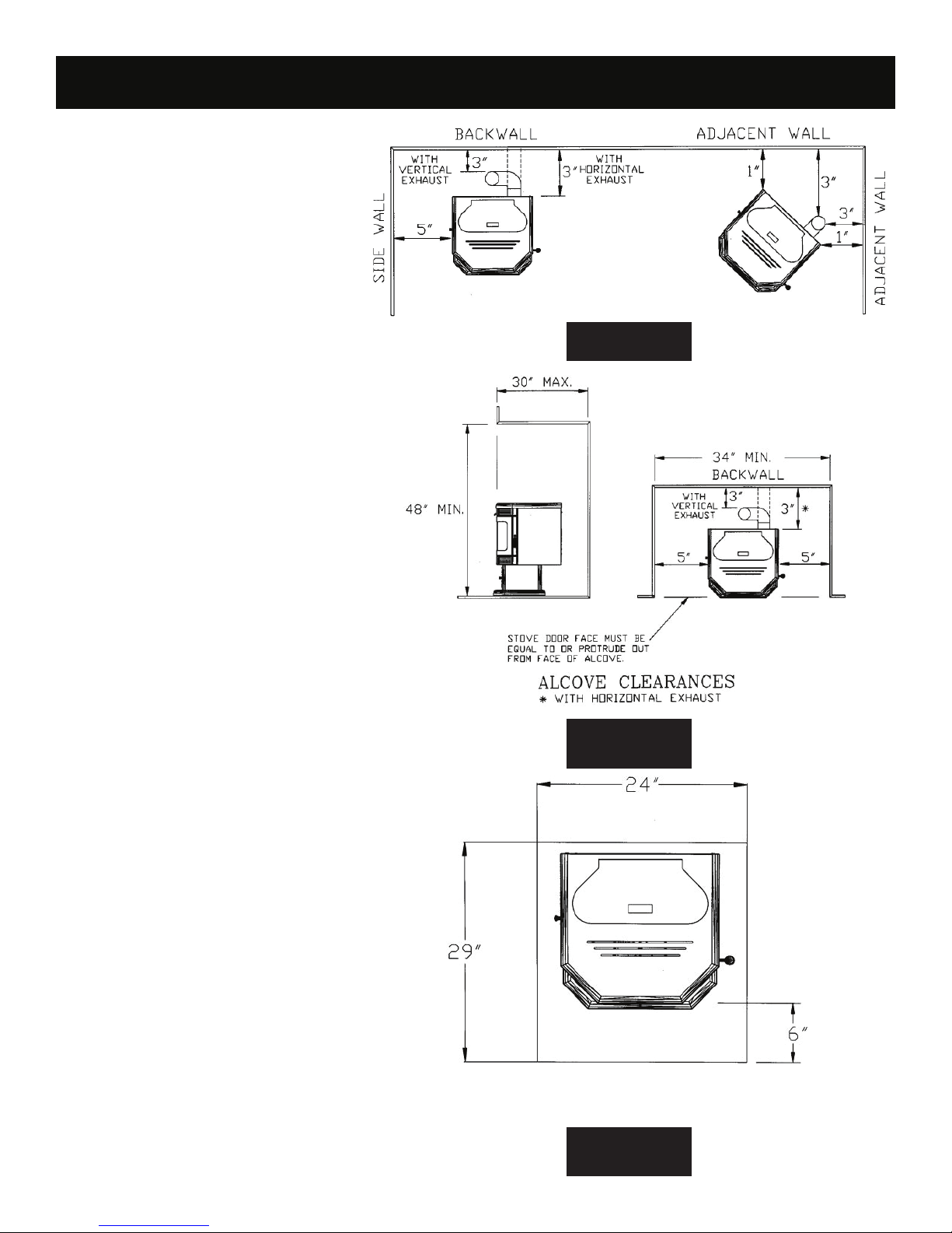
CLEARANCES
The Breckwell SSP2700 Freestanding has been
tested and listed for installation in residential, mobile home and alcove applications.
FIGURE 1
FLOOR PROTECTION: Freestanding installations, minimum 24” wide by 29” deep. The stove
must be placed on a continuous (grouted joints)
noncombustible material such as ceramic tile, cement board, brick, 3/8” millboard or equivalent, or
other approved or listed material suited for fl oor
protection. NOTE: ceramic tile, or any tile, requires a continuous sheet beneath to prevent the
possibility of embers falling through to the combustible fl oor if cracks or separation should occur
in the fi nished surface, this would include fl oor
protection for Built-in raised hearths. Check local
codes for approved alternatives.
Clearances are measured from the sides, back
and face (door opening) or stove body (refer to
fi g. 3).
DO NOT USE MAKESHIFT MATERIALS OR
COMPROMISES IN THE INSTALLATION OF
THIS UNIT.
INSTALL VENT WITH CLEARANCES SPECIFIED BY THE VENT MANUFACTURER.
FIGURE 2
6
FLOOR PROTECTION
(MINIMUM 24” W X 29” D)
FIGURE 3
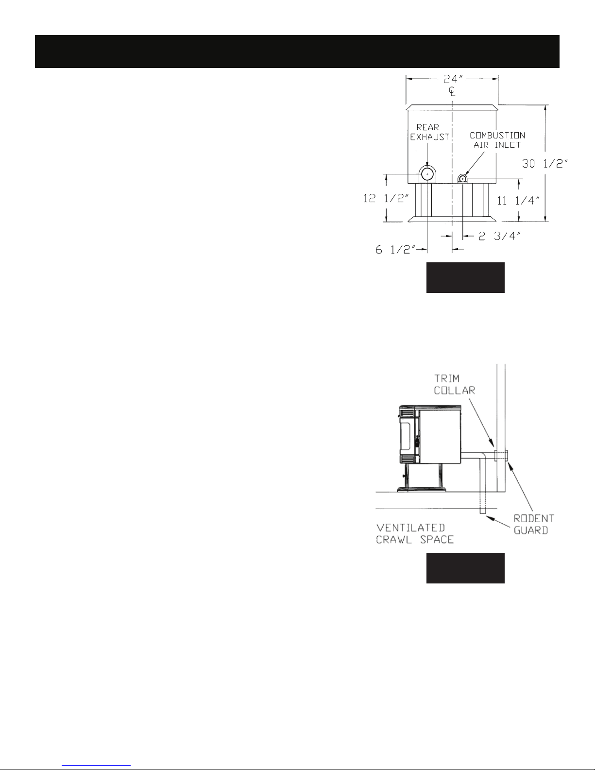
INSTALLATION
INSTALLATION
COMBUSTION AIR SUPPLY
For a mobile home installation the stove must be connected to an outside source
of combustion air. A 2” inside diameter metallic pipe, either fl exible or rigid, may be
attached to the inlet at the stove’s rear (refer to fi gure 4). A rodent guard (minimum
¼” wire mesh)/wind hood must be used at the terminus (refer to fi gure 5). All con-
nections must be secured and airtight by either using the appropriately sized hose
clamp and/or UL-181-AP foil tape.
For mobile home installations only: 2” inside diameter pipe may be used for the
fi rst 5 feet of combustion air supply run. From 5 to 10 feet use 2 ¾” inside diameter
pipe. No combustion air supply may exceed 10 feet.
Sources of Outside Combustion Air
a. In fi replaces
• Chimney top.
• Ash clean out door.
b. For freestanding installations
• A hole in fl oor near stove rear terminating only in a ventilated crawl space.
• A hole in the wall behind the stove.
WHEN OUTSIDE AIR IS NOT USED
If outside air is not used, it is important that combustion air is easily available to the
air inlet. A closeable outside air register can be used in tightly insulated homes.
IMPORTANCE OF PROPER DRAFT
Draft is the force which moves air from the appliance up through the chimney. The
amount of draft in your chimney depends on the length of the chimney, local geography, nearby obstructions and other factors. Too much draft may cause excessive
temperatures in the appliance. Inadequate draft may cause backpuffi ng into the
room and ‘plugging’ of the chimney.
Inadequate draft will cause the appliance to leak smoke into the room through appliance and chimney connector joints.
An uncontrollable burn or excessive temperature indicates excessive draft.
Take into account the chimney’s location to insure it is not too close to neighbors or
in a valley which may cause unhealthy or nuisance conditions.
FIGURE 4
VENTING
The Breckwell SP2700 is certifi ed for use with listed TYPE L-Vent, 3” or 4” diameter
in size. The stove was tested with Simpson Duravent brand. Class “A” chimney is
not required. Refer to the instructions provided by the vent manufacturer, especially
when passing through a wall, ceiling or roof.
This is a pressurized exhaust system. All vent connector joints must be sealed with
500°F (260°C) RTV silicone sealant to ensure consistent performance and avoid
smoke spillage. All horizontal connector joints must be sealed with UL-181-AP foil
tape. We recommend that all vertical vent connector joints be secured with a minimum of 3 screws.
It is strongly recommended that you have a minimum of 6’ of vertical pipe in your
exhaust system. For best performance of the stove limit the number of elbows and
horizontal pipe as much as possible
DO NOT CONNECT THIS UNIT TO A CHIMNEY FLUE SERVING ANOTHER APPLIANCE.
DO NOT INSTALL A FLUE DAMPER IN THE EXHAUST VENTING SYSTEM OF
THIS UNIT.
INSTALL VENT AT CLEARANCES SPECIFIED BY THE VENT MANUFACTURER.
FIGURE 5
7
INSTALLATION
INSTALLATION
EQUIVALENT VENT LENGTH (EVL)
The longer the run of pipe in your installation, the more restriction there is in the system. Therefore, larger diameter pipe should be used.
• Use 4” pipe if you have more than 15 feet of equivalent vent length.
• Horizontal runs shall not exceed 10’ of EVL.
• Recommended vertical runs to be a minimum of 8’.
• To calculate EVL, use the following conversions:
90º elbow or “T” = 5 equivalent feet
45º elbow = 3 equivalent feet
Horizontal Pipe Run = 1 equivalent foot per actual foot
Vertical Pipe Run = 0.5 equivalent foot per actual foot
NOTE: At altitudes above 3,000 feet, we suggest the use of 4” diameter vent at an EVL of 7 feet or more.
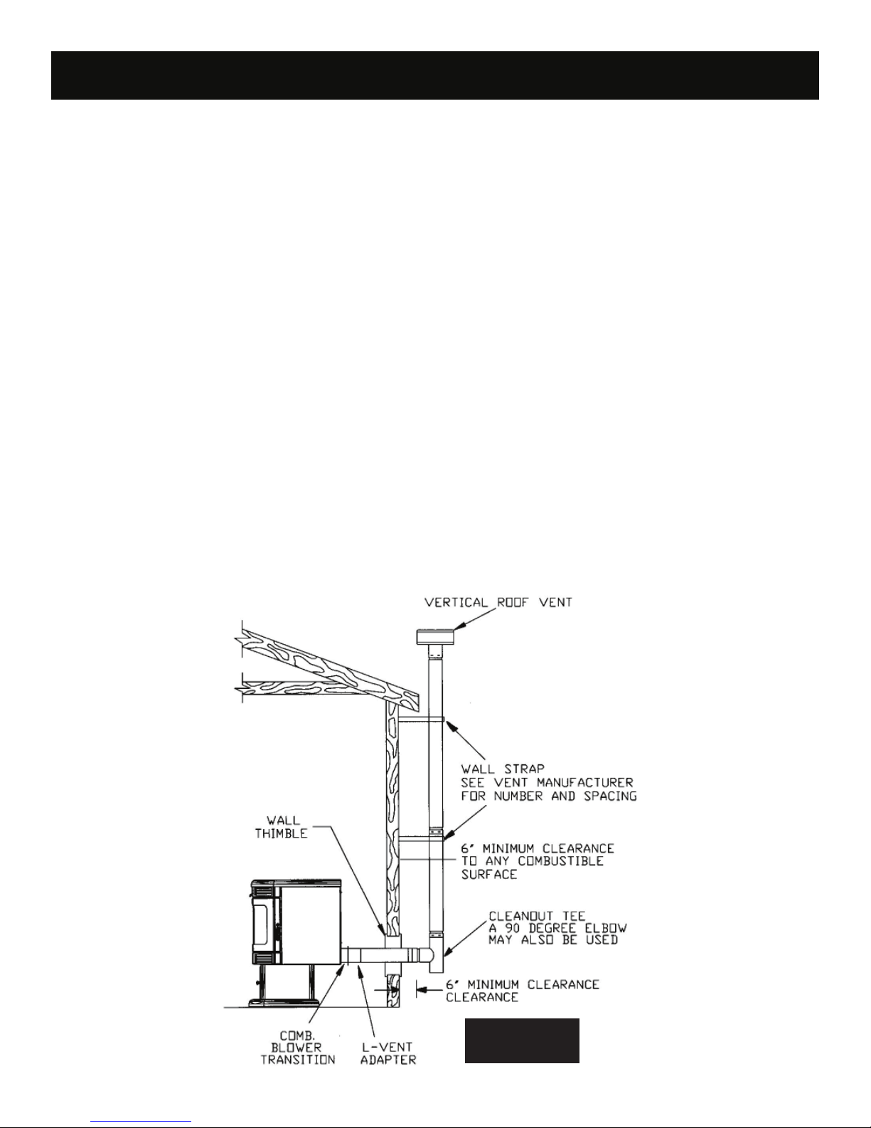
SP2700 INSTALLATION
A. HORIZONTALLY THROUGH WALL (refer to Figure 6)
NOTE: Follow L-Vent chimney manufacturer’s instructions.
1. Position stove, adhering to clearances shown in Figures 1 & 2.
2. Locate position of hole in wall; directly behind stove exhaust vent (refer to fi gure 4).
3. Always maintain 3” clearance from combustible materials.
4. Install L-Vent wall thimble per L-Vent manufacturer’s instructions.
5. Attach enough piping to penetrate and extend at least 6” beyond exterior walls. An 8-foot vertical pipe run is suggested where possible to reduce the possibility of smoke spillage in the event of a loss of negative pressure.
6. Attach cap and seal outside wall thimbles with non-hardening waterproof mastic.
7. Termination should not be located so that hot exhaust gases can ignite trees, shrubs, or grasses or be a hazard to children. Exhaust
gases can reach temperatures of 500ºF and cause serious burns if touched.
Locate terminations: a) not less then 3 feet above any forced air inlet located within 10 feet; b) not less than 4 feet below or horizontally
from, or one foot above, any door, window or gravity air inlet into any building; c) not less than two feet from an adjacent building and not
less than 7 feet above grade when located adjacent to a public walkway.
8
FIGURE 6
INSTALLATION
INSTALLATION
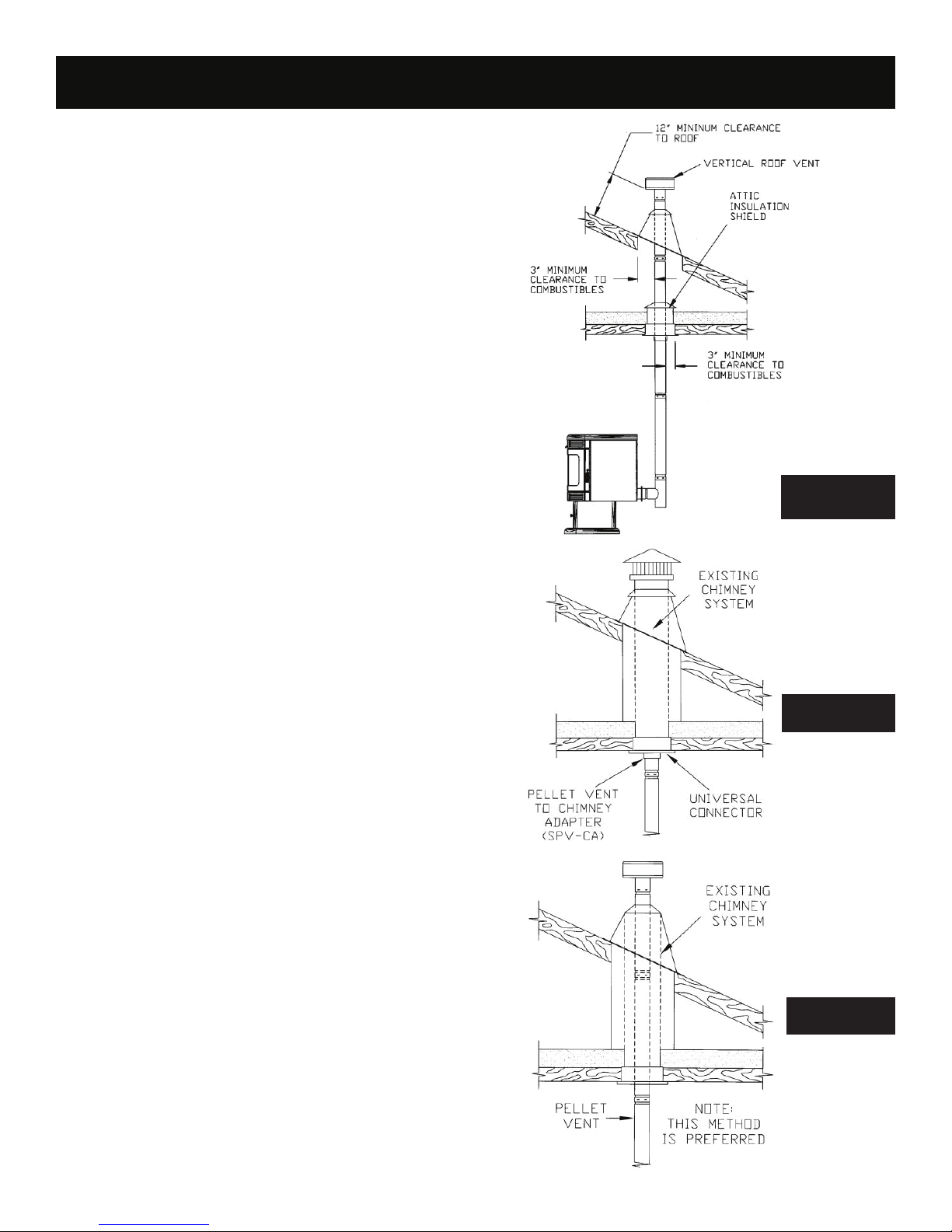
B. VERTICALLY WITH NEW CHIMNEY SYSTEM
(Refer to Figure 7)
NOTE: Follow L-Vent chimney manufacturer’s instructions.
OPTION: To achieve a center vertical installation a 45º elbow and a
clean-out tee can be used to offset the pipe from the exhaust outlet to
the rear center of the stove.
OPTION: Install L-Vent elbow in place of clean-out tee. Locate stove.
Drop plumb bob to center of tee outlet, mark point on ceiling. Install
ceiling support and L-Vent pipe per L-Vent manufacturer’s instructions.
1. Always maintain 3” clearance from combustible materials. When
passing through additional fl oors or ceilings, always install fi restop
spacer.
2. After lining up for hole in roof, cut either around or square hole in
roof, always 3” larger all the way around pipe. Install upper edge
and sides of fl ashing under roofi ng materials, nail to the roof along
upper edge. Do not nail lower edge. Seal nail heads with nonhardening waterproof mastic.
3. Apply non-hardening, waterproof mastic where the storm collar will
meet the vent and fl ashing. Slide storm collar down until it sits on
the fl ashing. Seal and install cap.
C. VERTICALLY INTO EXISTING CHIMNEY SYSTEM
Adapters are available to adapt from 3” L-Vent to 6” or 8” Class-A chimney. (Figure 8a)
As an alternative, 3” or 4” L-Vent can be run inside existing chimney to
termination. (Figure 8b)
This is the preferred method.
Follow guidelines for equivalent vent length.
D. VERTICALLY INTO EXISTING MASONRY FIRELACE
NOTE: Follow L-Vent chimney manufacturer’s instructions.
1. Have the masonry chimney inspected by a qualifi ed chimney
sweep or installer to determine its structural condition.
2. You will need a pipe length equal to the chimney height from the
hearth. If outside combustion air is to be used, you will need a pipe
length equal to the chimney height plus 18 inches.
3. Install a blanking plate and the chimney pipe, and if used the outside air pipe, as shown in Figure 9.
4. Attach the L-vent adapter, a section of pipe and clean out tee,
making sure the clean out tee is centered in the chimney fl ue area.
Use RTV, metallic tape, and a minimum of three self-taping screws
at all joint connections to ensure a tight seal.
5. Position the stove, adhering to the clearances in Figures 1 & 2.
6. Measure and build chimney top plate. Cut out holes for chimney
pipe, and if used the outside air pipe. Install and seal with nonhardening mastic to prevent water leakage. Install vent cap.
FIGURE 7
FIGURE 8a
FIGURE 8b
9
 Loading...