


Breas Medical PV 401-2 Service Manual

Service Manual PV 401-2
TABLE OF CONTENTS
1 INTRODUCTION ............................................................................................................ 1
1.1 Intend ed use of the ven t ilat or ...........................................................................1
1.2 Design and function of the ventilator................................................................ 1
1.3 The scope of this manual .................................................................................1
1.4 Intended audience ...................... .............. ............... ............... .............. ............1
1.5 Servic e personnel's t raining requ irements .......................................................1
2 OPERATING MANUAL (Reference copy)
3 MAINTENANCE SERVICE INSTRUCTIONS ................................................................1
3.1 Verifyi ng t he compone nt s and software ins t alled....................... ............... ....... 1
3.2 Special s afety preca ut ions ............................................................................... 1
3.3 Equipment and too ls required ..........................................................................1
3.4 Replacement parts required ............................................................................. 1
3.5 Maintenance service instructions .....................................................................2
3.6 Service schedule ..............................................................................................2
3.7 External checks ................................................................................................ 3
3.8 Internal checks .................................................................................................4
3.9 Final checks before handing over ................ ............... .............. ............... ........5
4 REPLACEMENT PARTS .............. .............. ............... ............... .............. ............... ........1
4.1 General view ....................................................................................................1
4.2 Parts drawing - Motor, Circuit Boards and Transformer................................... 2
4.3 Parts drawing - Casings, Panels, Decals, Valves and Filters........................... 3
4.4 Parts drawing - Motor Unit................................................................................ 4
4.5 Parts drawing - Tubes and connections............................................................ 5
4.6 List of replacement parts ............... ............... ............... .............. ............... ........6
5 FUNCTIONAL DIAGRAMS ... ............... ............... .............. ............... ............... .............. .1
5.1 Pneumatic diagram . ............... ............... .............. ............... ............... .............. .1
5.2 Functional block diagram ... ............... ............... .............. ............... ............... ....2
6 REMOVING/REPLACING THE MAIN COMPONENTS................................................. 1
6.1 Removing the upper casing.............................................................................. 1
6.2 Removing/replacing the pushbutton membrane panel .....................................2
6.3 Removing/replacing the CPU board .................................................................3
6.4 Removing/replacing the MDA board ................................................................4
6.5 Installat ion of Internal Battery Kit (a c c es s ory) .................................................. 6
6.6 Upgrading the software............... .............. ............... ............... .............. ............8
6.7 Programming the software................................................................................ 9
6.8 Removing/Replacing the PGC board............................................................. 11
6.9 Localisation of air tubes .................................................................................. 12
6.10 Removing/replacing the rear panel complete with transformer ......................13
6.11 Removing/replacing the I/O board ..................................................................14
6.12 Removing/replacing the MFC board ...............................................................14
6.13 Removing/replacing the transformer ..............................................................15
6.14 Removing the motor unit from the lower casing .............................................16
6.15 Reassembling/replac ing the motor unit ..........................................................17
Doc. No. 1527En Issue: M-2 BREAS MEDICAL

Service Manual PV 401-2
7 MOTOR UNIT .................................................................................................................1
7.1 Construction ..................................................................................................... 1
7.2 Removing the motor unit.................................................................................. 2
7.3 Inspectin g/re pla ci ng the drive belt ............... ............... ............... .............. .........2
7.4 Lubricating the ballscrew ..................................................................................2
7.5 Replacing the membrane in the check valves .................................................4
7.6 Tubes a nd bellows, leakage check ........................ ............... ............... ............6
7.7 Replacing the ballscrew assembly ......................... ............... ............... ............8
7.8 Replacing the bearing housing assembly .......................................................10
8 ELECTRONICS .............................................................................................................. 1
8.1 Function and constructi on ......... ............... .............. ............... ............... ............1
8.2 Circuit boards ...................................................................................................3
8.3 Main cabling diagram .......................................................................................8
8.4 Test points ........................................................................................................9
8.5 Calibrat ion of pressure sensors ...................................................................... 11
8.6 Ventilato r switch -over operat i ng voltages .... ............... ............... .............. .......13
8.7 Checking the internal battery.......................................................................... 14
8.8 Checking external battery operation ............................................................... 15
8.9 Replacing the alarm battery BT1 and memory battery BT2 ...........................16
8.10 Setting the Date and Time ..............................................................................17
8.11 Erasing the Calendar memory ........................................................................17
8.12 Electrical safety precautions ...........................................................................18
8.13 Circuit diagrams .............................................................................................19
8.14 Component location drawings ........................................................................39
8.15 List of Components ........................................................................................45
9 FAULT TRACING ........................................................................................................... 1
9.1 Fault tracing scheme ........................................................................................1
9.2 Error codes .......................................................................................................2
10-1 ENGINEERING HISTORY........................... .............. ............... ............... .............. .........1
10-2 SERVICE RECORD........................................................................................................ 1
10-3 RETURNING GOODS TO BREAS .................................................................................1
BREAS MEDICAL Doc. No. 1527En Issue: M-2

Service Manual PV 401-2 INTRODUCTION
1 INTRODUCTION
1.1 Intended use of the ventilat or
The PV 401-2 is a pressure-con trolled, pressure -monitored ventilator, especially
developed for treatm ent in the ho m e of patients w it h c hronic breat hing difficultie s .
The PV 401-2 m ay be used fo r total li fe support on condit ion that either an external ba ttery and/o r an internal ba c ku p battery pack is installed as an extra ba c k up
supply should the main s su pply fail or be disc onnected.
The PV 401-2 is designed to give many years of trouble-free breathing assistance
to the user provided that preventive maintenance is done at the specified intervals
describe d in this manua l. The service intervals vary due to the type of op eration
for which th e v entilator is use d.
Well-performed maintenance services will increase service life of the ventilator
consider ably. It is also important that any periph eral equip ment is ch ecked at the
time the se rv ic e is c arried out.
1.2 Design and function of the ventilator
The PV 401-2 is constructed around a bellows which is driven by a ball screw assembly. An electronically-controlled servo-motor rotates the ball screw via a belt transmission, thus moving the bellows up or down. A microprocessor controls the correct
speed of the motor an d its p owe r sup ply b y m eans of calcu latio ns ba sed on the settings for pressure, rate, inspiration time etc. The pressure and trigger se ttings are
monitored at the same time.
In the event of a m ains power failure, the ventila t or w ill automatica lly switch to the
external battery supply (if installed) . Should this no t be available, it will switch to
the interna l bat t ery s upply (if installe d). T his power source being used is indi ca t ed
in the LCD di spla y. If the external b atte ry volt age d rop s too lo w, an audib le alarm
is giv en.
1.3 The scope of this manual
All routine maintenance checks and additional service actions for the PV 401-2
are desc ribed in this m anual. The m anual cont ains all docu m entation re quired for
maintenance and service, such as replacement parts lists, exploded drawings,
wiring diagrams, component location guides, etc.
Breas Medical reserves the right to make changes to the product and the contents
of this man ual without prior notice.
1.4 Intended aud ien ce
This Servic e M anual is inte nded for technic ians who have medical/t ec hnical training and know ledge of the co ns t ruc t ion and function of the vent ilator.
It is not intended for clinic personnel or patients.
1.5 Service personnel's training requirements
Thanks to the simple construction of the PV 401-2, no special competence other
than general medical technical train ing on ventilators is require d.
Always contact BREAS MEDICAL if there are any questions or if training is required.
All service m ust, however, be performed as desc ribed in this manual.
Doc. No. 1527En Issue: M-2 BREAS MEDICAL 1 – 1

INTRODUCTION Service Manual PV 401-2
1 – 2 BREAS MEDICAL Doc. No. 1527En Issue: M-2

Service Manual PV 401-2 MAINTENANCE SERVICE INSTRUCTIONS
3 MAINTENANCE SERVICE INSTRUCTIONS
All routine maintenance checks and additional service instructions for the PV 401-2 are
describe d in t his chapter. For information about fa ult -t racing, detailed drawings , board
schematics, spare parts etc, please refer to the respective chapter in this Service
Manual.
A Patient Instruction manual is supplied with the ventilator and the checks described
there sho uld be followed by th e patient and /o r c are providers .
Before starting the maintenance se rv ic e, read the Spec ial Safety Prec autions section
and have a new Service R ec ord (photoc opy the exam ple in the Appendices chapt er)
and all the necessary eq uipment, too ls and replacem ent parts at ha nd.
3.1 Verifying the components and software installed
Check the Engineering Change History in the Appendices for a history of changes
made, an d fr om w hich serial nu m ber they were im plemented .
If in any doubt, read the component designation on circuit boards and PROMs, as
upgrade s ma y hav e been made w hich have no t been recorded in the Engineering
Change History.
3.2 Special safety precautions
• Do not work on the vent ilator with the casing remo ve d and the powe r s upply
connected.
• Explos iv e gases and fluids must not be used near th e v entilator.
• Take all necessary ESD precautions.
3.3 Equipment and tools required
A test lung or reservoir ba g.
A measur ing instrument fo r t idal volume an d m inute volume/rate (Biotek Ventilator
tester, Timeter, Spirometer or equivalent).
A universa l ins t rument.
A standar d t oolkit contain ing screwdriv ers , Allen keys, Torx keys and socke ts.
A new Service R ec ord (photoco py th e Service Record in the Appendices sec t ion of this
binder).
3.4 Replacement parts required
The following parts should be available when se rv ic ing.
Part No.
204020 Patient c irc uit
215090 Servic e k it inc l. m em branes, 0-r ings for check v alv es and drive b elt
205180 Memb rane assembly f or exhalation va lv e
285911 Grease (BREAS 240 AC)
1445 Air filter, patient air, washa ble
1428 Air filter, patient air, dispos able
If required :
215100 Intern al battery kit
205680 Batter y for alarm (Ni-Cd)
205490 Motor Un it Kit fo r replacemen t at 2 0, 000 operating hours
Description
Doc. No. 1527En Issue: M-2 BREAS MEDICAL 3 – 1

MAINTENANCE SERVICE INSTRUCTIONS Se rvice Manual PV 401-2
3.5 Maintenance service instructions
The maintenance service comprises the checks liste d in the table below. The reference
numbers stat ed refer to the C hapter and Sec t ion in this manual where det ailed instructions can be found.
3.6 Service schedule
IMPORTANT!
A complete maintenance service (as described in this chapter) must be done every
12th month. If the ventilator is used for continuous operation (24 hours per day)
a complete maintenance service must be done every 6th month.
Every 12th month, or every 6th month if the ventilator is used for
continuous operation (24 hours per day).
Motor Unit
Change drive belt
Lubricat e ballscrew 7.4
Change c heck valve membranes and O-rings 7.5
Leakage test of motor unit and tubes 7.6
Electronics
Calibrat e pressure sens or 8.5
Check operation usin g internal bat te ry (w here applicable) 8.6
Check operation usin g external ba ttery (where ap plicable) 8.7
Check electrical safety levels 8.11
Accessories (where applicable)
Inspect patient circuit 2
See Ch./
Section
No.
7.3
Change m embrane in ex halation va lv e 3.9.10
Clean PEEP adapter, change O-ring 3.9.10
Every 24 mo n th s
Replace th e internal battery pack 6.5
Every 5th year
Change alarm batteries
Every 20,000 operating hours
Change the complete motor unit
3 – 2 BREAS MEDICAL D oc. No. 1527En Issue: M-2
8.8
6.13

Service Manual PV 401-2 MAINTENANCE SERVICE INSTRUCTIONS
3.6.1 Open a new Service Record, identify and register the ventilator
• Make a copy of the Serv ic e R ecord in the A ppendices chapter.
• Fill out the m odel, seria l num ber and any inventory num ber on the Service Recor d.
• Check any commen t s re c orded on previous Service Records.
• Document the current patient se ttings.
3.6.2 Additional Services Required
• Check t he number of op erating hours and enter it on the service rec ord.
• Check the service schedule to see whether the alarm batteries, internal battery kit
or the complete motor unit are due to be replaced.
3.6.3 Markings
Make sure t hat all markings on labels can be read:
• Make, m odel descrip ti on, s erial number.
• Warning text s.
• Any inve nt ory markings .
• All other texts etc.
3.6.4 Information from the user
Check the following with the patient:
• Has the f unc t ion of the vent ilat or been trouble-free? If not , w hat problems have
there been?
• How do es th e patient chec k th e fu nc t ion of the vent ilat or? How ofte n?
• How oft en has the filter b een replaced?
• What filt ers w ill the patient need to last unt il t he next service?
• Other observations?
3.6.5 Validity of the technical documentation
• Check t he v alidity of the pa t ient instructions.
• Check if any m odification or upgrading of th e v entilator nee ds to be done at the
same time as the service.
3.7 External checks
3.7.1 Visual inspection for external damage and wear
• Clean th e outside using window-cleaning fluid.
• Check f or any visible dam age to the cas ings and othe r c om ponents.
• Check t hat nothing has wo rk ed loose (incl uding the handle).
Doc. No. 1527En Issue: M-2 BREAS MEDICAL 3 – 3

MAINTENANCE SERVICE INSTRUCTIONS Se rvice Manual PV 401-2
3.7.2 Power connection
• Check th e plugs on the p ow er cable, the c able itself and th e v entilator's p ow er
socket.
• Make sure that the strain relief clamp for the power cord is not dam aged.
• Inspect th e ex t ernal battery c able, if used.
• Check the external battery socket in the ventilator.
3.7.3 Minimum function check
• Connect the power cord.
• Connec t th e patient circu it.
• Switch on the ventilat or and make sure it operates normally.
3.8 Internal checks
3.8.1 Cleaning
• Remove the casing. See Chapter 6 Di smantling and Assembling the PV 401-2 for
instructions.
• Remove any dirt or dust t hat has collecte d in t he ventilator.
3.8.2 Cabling
• Inspect all cables and their connectors. Check the front and rear panels to make sure
that cables and wires are not pinch ed.
• Change any cable strap anchor that has become loose.
3.8.3 Fastening of components
• Make sure that all components, such as the motor, printed circuit boards, connectors,
etc are sec urely fasten ed.
3.8.4 Replace drive belt
• Refer to s ec t ion 7.3 for inform ation.
3.8.5 Lubricate ballscrew
• Refer to s ec t ion 7.4 for inform ation.
3.8.6 Replace membrane assemblies in check valves
• Refer to s ec t ion 7.5 for inform ation.
3.8.7 Power supply
• Make sure that the pow er socket is undamaged and is securely in place.
• Make sure that the tou c h-protection is undamaged and proper ly te ns ioned over th e
socket.
• Make sure the transfo rm er is securely fa s te ned.
• Check th e w iring to and fro m th e t ransformer.
3 – 4 BREAS MEDICAL D oc. No. 1527En Issue: M-2

Service Manual PV 401-2 MAINTENANCE SERVICE INSTRUCTIONS
3.8.8 Calibrate the pressure sensors
• Refer to C hapter 8.5 for information.
3.8.9 Reassemble the casing
• Refer to Chapter 6 for instructions.
3.8.10 El ectrical Saf ety
• Refer to C hapter 8.11 for informati on.
3.8.11 Leakage test of tubes and bellows
• Refer to C hapter 7.6 for information.
3.9 Final checks before handing over
3.9.1
Function check
• Connec t th e patient circu it , st art t he v entilator and c hec k t hat everythin g w orks normally.
3.9.2 Check low pressure/leakage alarm
• Set the p res s ure to 20 mba r.
• Create a leakage so that a pressure of 20mbar cann ot be reached.
• Check t hat t he alarm LED for PRESSU R E lights and that an audible ala rm is giv en.
3.9.3 Check low volume alarm
• Set the low volume limit to a value less than the volume of the test lung/reservoir bag.
• Check t hat t he alarm LED for VOLUME lights and that a n audible alarm is given.
3.9.4 Alarm mute
• Switch on the ventilator. Do not connect anything to the patient air connection. Wait
15 seconds for the "VOLUME" alarm to be activated. Press the mute button and
make sure the signal is muted. Make sure the signal is comes on again after approximately 2 m inutes.
3.9.5 Trigger
• Set the trigger to -0.5 mbar.
• Create a negative pre ssure and mak e s ure a triggered breath is given. The gree n
LED for Insp. Tr ig. should light.
Doc. No. 1527En Issue: M-2 BREAS MEDICAL 3 – 5
MAINTENANCE SERVICE INSTRUCTIONS Se rvice Manual PV 401-2
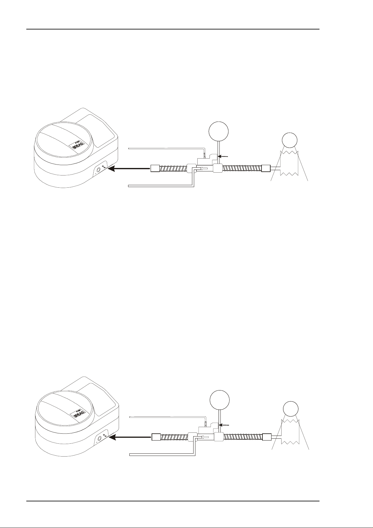
3.9.6 Checking the pressure/rate
• Adjust the settings to:
Pressu re: 20 mbar
Rate: 10 BPM
Insp: 3.0 sec
Mode: PCV
Test lung/
Reservoir bag/
Peep valve connector
Fig. 3-1 Checking pressure and rate
mbar
Volume monitor
Ventilator tester
• Measure and check that the pressure, rate and insp. time are correct, (accuracy
± 10%). The measuring should be done with a test lung or a reservoir bag connected.
(If these are not available, block the exhalation valve in the patient circuit.)
3.9.7 Checking the tidal volume indication
If a ventilator tester Biotek VT-1 or 2 is used, the estimated tidal volume can be tested
as follows:
• Set the compliance of the test lung to 0.02 L/cm H
• Select volume measuring
• Set the PV 401-2 as follo w s:
Pressu re: 30 mbar
Rate: 8 BPM
Insp: 5.0 sec
Mode: PCV
When che c k ing using a volu m e m onitor, an exhalation valve with a PEEP valve connector is requi red. The volum e m onitor is then c onnected to t he PEEP valve outlet on the
exhalat ion valve outlet .
Peep valve connector
O
2
mbar
Test lung/
Reservoir bag/
Ventilator tester
Volume monitor
Fig. 3-2 Checking tidal volume
• Check the accuracy (± 20%).
3 – 6 BREAS MEDICAL D oc. No. 1527En Issue: M-2

Service Manual PV 401-2 MAINTENANCE SERVICE INSTRUCTIONS
3.9.8 External battery operation
• Connec t an external ba ttery.
• Disconnect the pow er c ord while the ve nt ilator is runnin g.
• Check t hat t he ventilator automatica lly switches ove r to ex te rnal battery operation.The following indications should be given:
- an audib le alarm (not if th ere is an intern al battery installed)
- the LED in the ON/OFF button should start to flash
- the letter E should be dis played in the POWER field.
• Reconnect the power cord and make sure th at t he LED in th e ON/OFF but ton shows
a steady light, the audible alarm stops and the le tter M is display ed in the POWE R
field.
3.9.9 Internal battery operation
• Disconnect any external battery.
• Disconnect the pow er c ord while the ve nt ilator is runnin g.
• Check t hat t he ventilator automatica lly switches ove r to int ernal battery operation.
The follo w ing indicatio ns s hould be given:
- an audible alarm
- the LED in the ON/OFF button should start to flash
- the letter E should be dis played in the POWER field.
• Reconnect the power cord and make sure th at t he LED in th e ON/OFF but ton shows
a steady light, the audible alarm stops and the le tter M is display ed in the POWE R
field.
Doc. No. 1527En Issue: M-2 BREAS MEDICAL 3 – 7
MAINTENANCE SERVICE INSTRUCTIONS Se rvice Manual PV 401-2
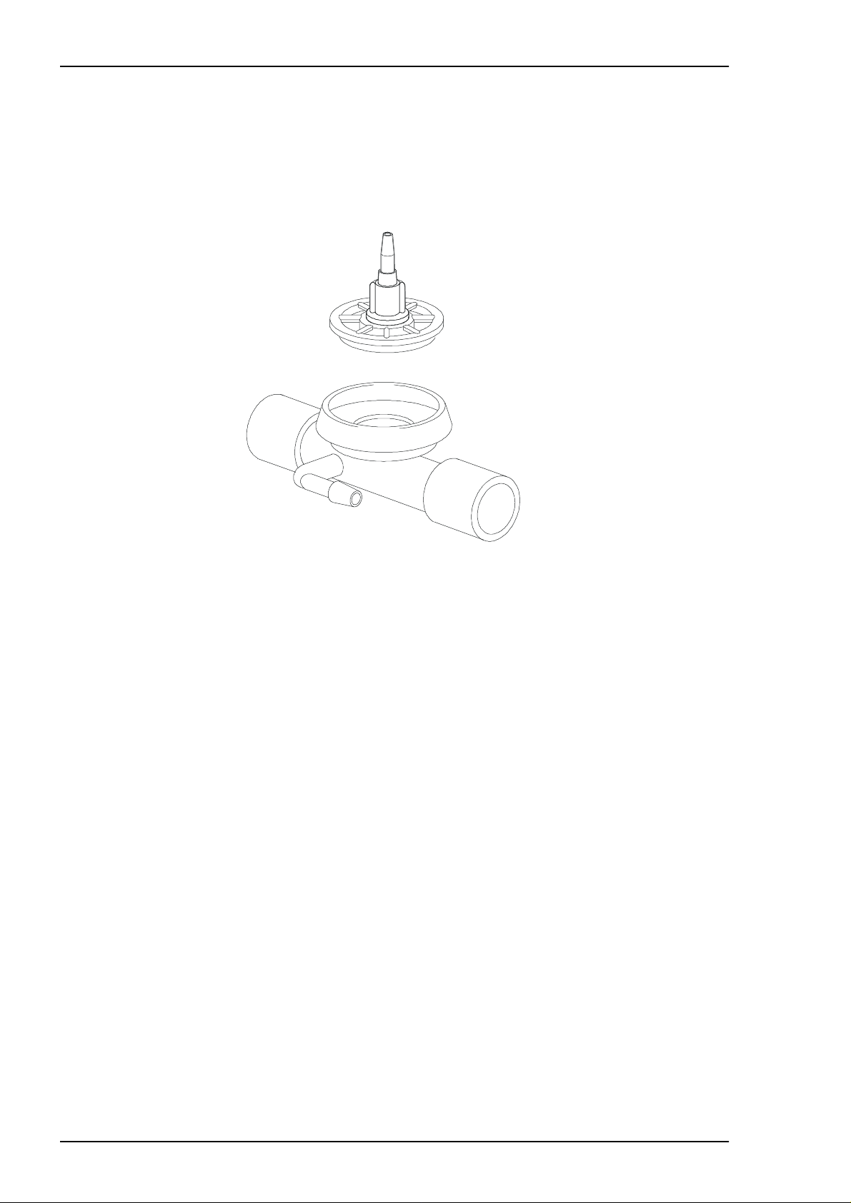
3.9.10 Checking accessories
Patient circ uit
• Inspect th e patient circu it and change if ne c es s ary.
Changing the membrane in the exhalation valve
This instru c tio n applies to BREAS exhalat ion valves (s ee f igure below).
Fig. 3-3 Breas ex halation val ve
• Remove the PEEP adapter, if fitted, see Cleaning the PEEP adapter.
• Unscrew the complete membrane assembly, see fig.3-3.
• If a PEEP adapter is installed, take care of the O-ring seal.
• Clean th e ins ide of the exhalation valve using a moist rag (Clean according to loc al
regulations).
• Screw o n th e new membrane assembly.
• If a PEEP valve is to be used, fit the O-ring seal for the PEEP valve, as shown in the
bottom f igure on the nex t page.
• Connec t the exhalation valve to a test lung. Ch ec k tha t no leak age occurs during the
exhalat ion phase.
3 – 8 BREAS MEDICAL D oc. No. 1527En Issue: M-2
Service Manual PV 401-2 MAINTENANCE SERVICE INSTRUCTIONS
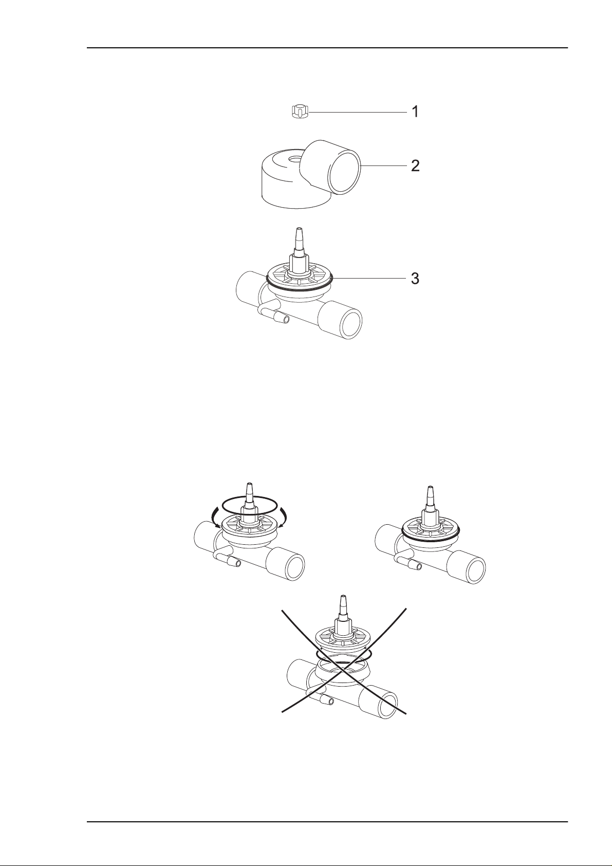
Cleaning the PEEP adapter
Fig. 3-4 Peep a dapter
• Remove the plastic nut (1) holding the PEEP adap te r.
• Pull the adapter (2) up f rom the exhalat ion valve. Do not remove the O-ring (3).
• Clean us ing a moist rag (C lean accord ing to local reg ulations).
• Check t hat t he O-ring seal is still properly in place. If not, fit it to t he exhalation va lv e
as shown in figure 3-5. D o
screwing it on.
not
fit the O-ring to the exhalat ion valve cov er before
Fig. 3-5 Fitting O-ring to exha lation valve
• Fit the PEEP adapter t o t he exhalatio n v alv e and screw on the plastic n ut .
Check any other accessories.
Doc. No. 1527En Issue: M-2 BREAS MEDICAL 3 – 9

MAINTENANCE SERVICE INSTRUCTIONS Se rvice Manual PV 401-2
3.9.11 Change/wash patient filters
• Change t he white air filte r. Make sure that the pat ient has a supply of fi lt ers t o las t to
the next service point.
• Wash or change the grey filte r if nec essary.
3.9.12 Adjust the settings for the patient
• Adjust the settings as prescribed fo r th e patient.
3 – 10 BREAS MEDICAL Doc. No. 1527En Issue: M-2
Service Manual PV 401-2 REPLACEMENT PARTS
4 REPLACEMENT PARTS
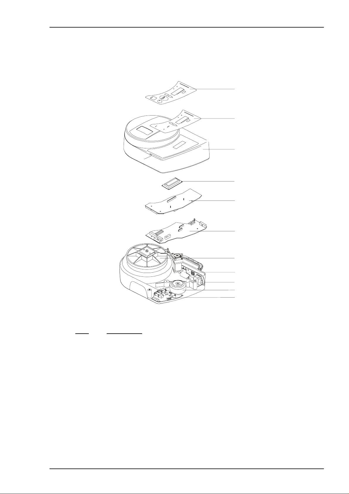
4.1 General view
1
2
3
4
5
6
7
8
9
10
11
Fig. 4-1 PV401 -2, M ain compone nt s
Pos. Description
1 Panel decal
2 Memb rane pushbut t on pad
3 Upper c as ing
4 LCD display
5 CPU bo ard
6 MDA bo ard
7 Motor unit , co m plete (also available as ex c hange unit, pa rt No . 205680)
8 I/O bo ard
9 MFC board
10 Transformer
11 PGC board
Doc. No. 1527En Issue: M-2 BREAS MEDICAL 4 – 1
REPLACEMENT PARTS Service Manual PV 401-2
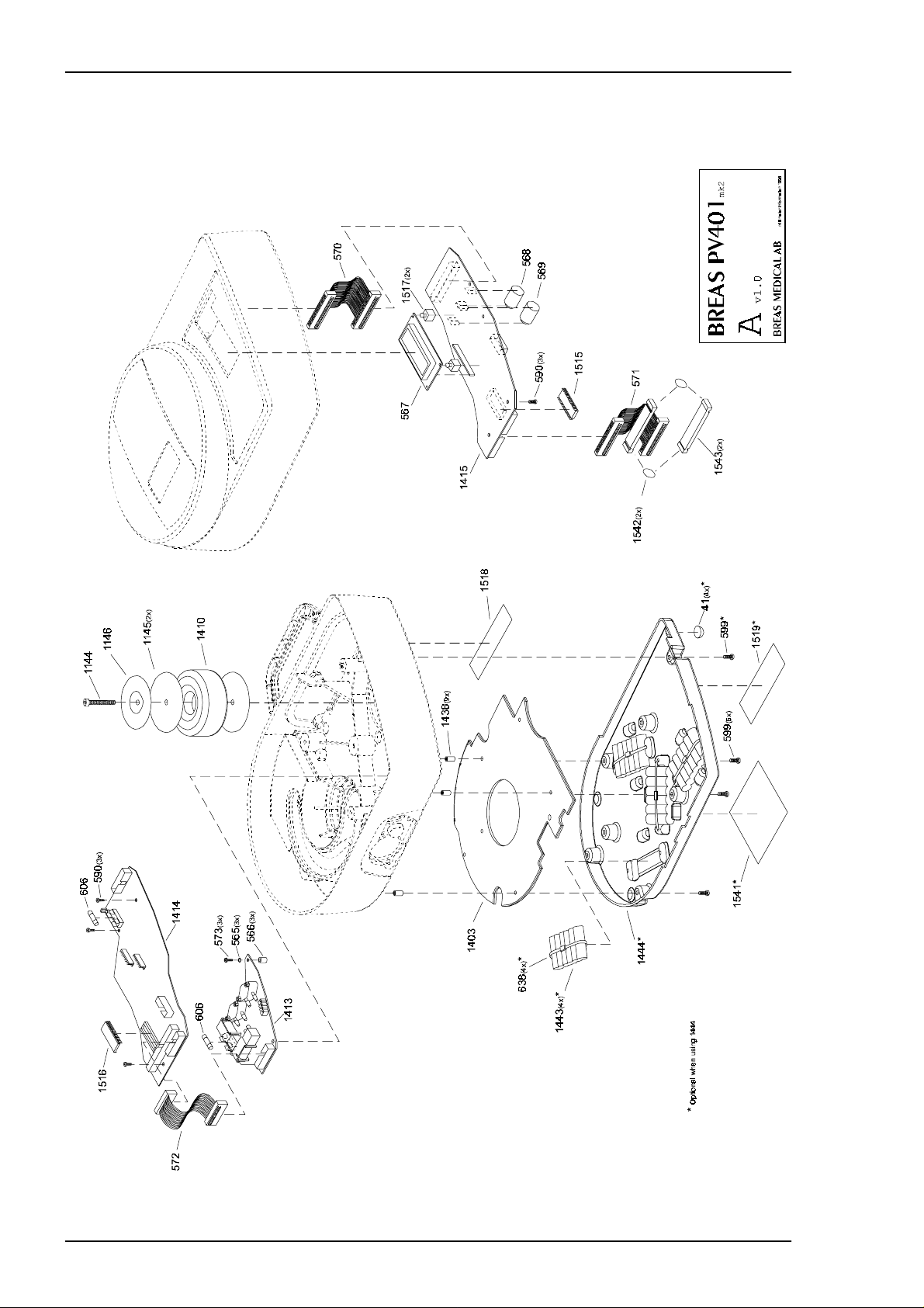
4.2 Parts drawing - Motor, Circuit Boards and Transformer
4 – 2 BREAS MEDICAL Doc. No. 1527En Issue: M-2
Service Manual PV 401-2 REPLACEMENT PARTS
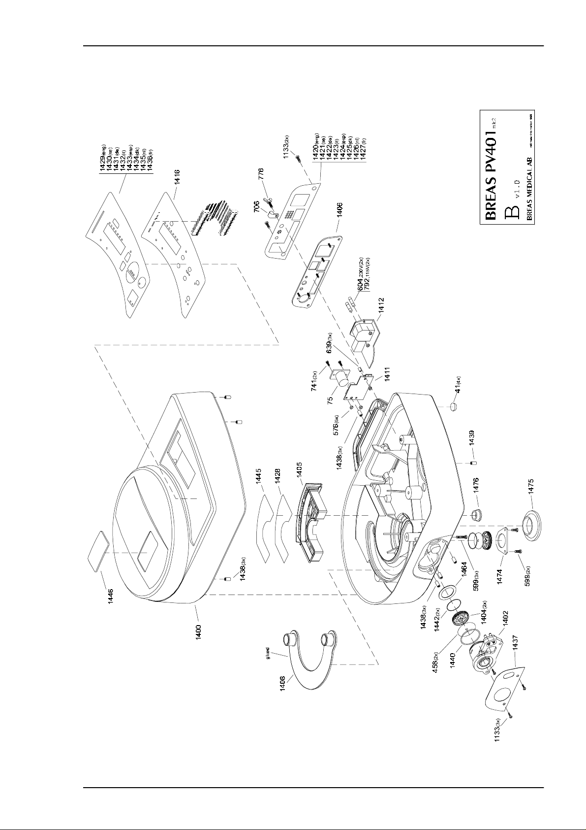
4.3 Parts drawing - Casings, Panels, Decals, Valves and Filters
Doc. No. 1527En Issue: M-2 BREAS MEDICAL 4 – 3
REPLACEMENT PARTS Service Manual PV 401-2
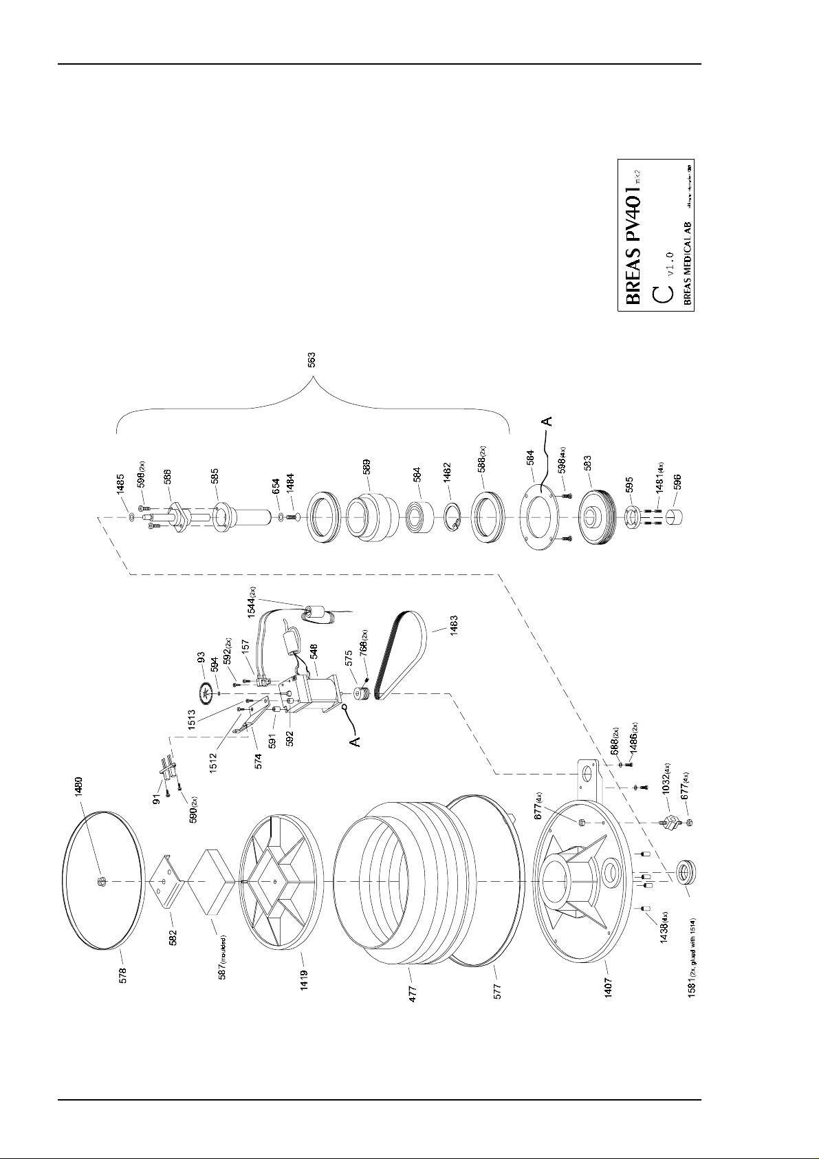
4.4 Parts drawing - Motor Unit
4 – 4 BREAS MEDICAL Doc. No. 1527En Issue: M-2

Service Manual PV 401-2 REPLACEMENT PARTS
4.5 Tubes and connections
Gray
Blue
Green
Transparent
Red
Doc. No. 1527En Issue: M-2 BREAS MEDICAL 4 – 5

REPLACEMENT PARTS Service Manual PV 401-2
4.6 List of replacement parts
Part No. Description
32 Pressu re s ensor
41 Rubber m ount - vibration absorbent (motor)
75 Chassis pin device
109 Magnet ic v alv e
458 Membrane, check valve PV 401
477 Bellows (mkII) PV 401-2
548 Motor (P V401-2)
549 Motor Unit PV401-2 c om plete
563 Motor Unit PV 401-2 Ex c hange unit
565 O-ring 3 x 3 nbr70 (fastening of tg-boa rd)
566 Tube2,5x6 blue 6 mm leng th (c ut fr om part No. 1054)
567 Display LCD (powert ip) for 401-2 w ith s oldered-on p in s tr ip
568 Alarm bat t ery 4,8 V Ni-MH 70 mAh l=25mm dia=17m m
569 Battery f or internal me m ory 3 V Lithium mAh l=25mm dia=17mm
570 Ribbon cable 40 pole with IDC l=100mm (CPU-Overlay)
571 Ribbon cable 50 pole with IDC connector l=100mm (CPU-MDA)
572 Ribbon cable 20 pole with IDC connector l=60mm (CPU-TG)
573 Screw RTX FXST 2,9 x 16 Fzb
574 Fastening bracket f or opto-switch (Scanac no 1654)
575 Pulley w heel motor po ly -V PV401-2 (S c anac no.165 3)
576 Nut M3 ny loc
577 Bellows c lam p, steel 325 m m 401-2 lower
578 Bellows c lam p, steel 215 m m 401-2 upper
581 Sealin g ring, air tube, w hit e s ilicon (Scan ac no. 1656)
582 Fastening plate for moving bellow s end cover PV 401-2
583 Pulley w heel large pol y- V PV401-2 (S ca nac no.1674 )
584 Flange
585 Shaft
586 Ballscrew with nut
587 Polyurethane elas to m er (Swedac U- 16 s oft end cover PV401-2)
588 Sealin g ring, bearing, w hit e s ilicon (Scan ac N o. 1657)
589 Bearin g s leeve
590 Screw RTK 2, 9x 9,5 fzb
591 Spacer piece DRM 4380x12
592 Spacer piece DRM 4380x10
593 Screw MRT 3x8 fzb
594 Washer 2,7x6x0,5 DIN 125
595 Cover n ut
596 Threaded cover
597 Ball bea ring, twin race angled contact bearing
598 Screw MRT 4x10 fzb
4 – 6 BREAS MEDICAL Doc. No. 1527En Issue: M-2

Service Manual PV 401-2 REPLACEMENT PARTS
599 Screw MRT 4x10 black-chromate
604 Fuse - T 315mA
606 Fuse - F 3, 15A
641 Blue Festotube
654 Washer - M6 - flat washer BRB 6,4fzb
677 Nut - M6M steel M4 NV7*3,2 FZB
706 Strain relief for cable, m ains
776 Screw- VS steel M4*12 FZB
792 Fuse, 630mA
1032 LF-iso lat or
1133 Screw MRT 4x14 black-chromate
1144 Screw MRX-Z 5x35 fzb
1 145 Washer rubber for transformer
1146 Washer, metal for transformer
1 148 Screw Phillips UNC thread for motor "Pittman 401-2" approx. 20mm
1 149 Screw Phillips UNC thread for motor "Pittman 401-2" approx. 15mm
1400 Casin g upper
1401 Casin g low er
1402 Outlet pat ient air
1403 Cover (over filter cassette)
1404 Valve - back seat
1405 Filter cas s ette
1406 Fastening plate rear panel
1407 Fixed end 401-2
1408 Cover (air channel
1409 Bellows 401-2
1410 Transforme r
1411 Circuit board D-sub
1412 Circuit board Power inlet
1413 Circuit board Magnetic valves
1414 Circuit board MDA
1415 Circuit board CPU
1416 Memb rane pushbut t on panel
1417 Drawin g decal outlet
1418 Drawin g decal fasten ing plate rear panel
1419 Movin g bellows end cover mold-in jected (Scanac no. 5014 5)
1420 Decal Re ar panel ENG
1421 Decal Re ar panel SE
1422 Decal Re ar panel DE
1423 Decal Re ar panel IT
1424 Decal Re ar panel ESP
1425 Decal Re ar panel DK
1426 Decal Re ar panel NL
1427 Decal Re ar panel FR
Doc. No. 1527En Issue: M-2 BREAS MEDICAL 4 – 7

REPLACEMENT PARTS Service Manual PV 401-2
1428 Filter PV 401-2 mk2
1429 Decal - pu s hbutton pan el/ LC D SE
1430 Decal - pu s hbutton pan el/ LC D ENG
1431 Decal - pu s hbutton pan el/ LC D DE
1432 Decal - pu s hbutton pan el/ LC D IT
1433 Decal - pu s hbutton pan el/ LC D ESP
1434 Decal - pu s hbutton pan el/ LC D DK
1435 Decal - pu s hbutton pan el/ LC D NL
1436 Decal - pu s hbutton pan el/ LC D FR
1437 Decal - pa t ient air outlet
1438 Screw- M 4 ins ert threade d Spreadsert 1
1439 Screw- M 5 ins ert threade d Spreadsert 1
1440 O-ring 3 7, 0* 2, 0 EPDM
1441 O-ring 3 5, 0* 1, 2 nitrile
1442 O-ring 2 8, 0* 1,3 EPDM
1443 Int.bat te ry pack 20 pcs nimh with cable
1444 Casing fo r battery pack 401-2
1445 Filter - coarse (PPI 45 )
1446 Logoty pe - polygloss panel
1447 Opera tin g m anual 401-2 SV
1448 Opera tin g m anual 401-2 EN G
1449 Opera tin g m anual 401-2 T Y
1450 Opera tin g m anual 401-2 IT
1451 Opera tin g m anual 401-2 ESP
1452 Opera tin g m anual 401-2 D K
1453 Opera tin g m anual 401-2 N L
1454 Opera tin g m anual 401-2 F R
1455 Opera tin g m anual 401-2 N OR SK
1456 Opera tin g m anual 401-2 F I
1457 Tube blue 2,5 *6 190mm silico n
1458 Tube blue 2,5 *6 125mm silico n
1459 Tube green 2, 5* 6 45mm silico n
1460 Tube green 2, 5* 6 45mm silico n
1461 Tube red 2,5*6 100mm silic on
1462 Tube neutral 2, 5* 6 65mm silico n
1463 Tube black 2,5 * 6 230mm silico n
1464 Seal silic on 35,5x25x1,0
1465 Circuit board - compl et e k it
1474 Lock was her for check va lv e PV402 (I-repro no. 6650)
1475 Bottom plug (Ulinco SR 1765 part no. 10517) for PV402
1476 Protec ti ve plug for interna l battery conn ec t or
1477 D-sub p rot ec t ion for female25 pole
1480 Nut flange nut DIN 6923 M5
1481 Stop screw P655 4x5 fzb
4 – 8 BREAS MEDICAL Doc. No. 1527En Issue: M-2

Service Manual PV 401-2 REPLACEMENT PARTS
1482 Groove ring SgH 47 s eeger Fuse "d p 401-2"
1483 Poly V-belt 4-170H
1484 Screw M F6 S 4x8 fzb
1485 Washer (alu m inium from Warner e lec t ric , 1675)
1486 Screw MRT 3x10 fzb
1510 Intern al battery kit PV 401-2 (1443 +1 444)
1511 Screw M 4 I ns ert thread Non-locking for wing bolt in re ar panel
1512 Screw 30 m m 5/ 32" (t mot. 548 fo r fa s t ening of bracket 574)
1513 Screw 15 m m 5/ 32" (t mot. 548 fo r fa s t ening of bracket 574)
1514 Glue silic on glue from Leewood for gl uing 581
1515 Software CPU PV401-2 EPROM (27C256 programmed)
1516 Software MDA PV401-2 EPROM (27C256 programmed)
1517 Spacer 9,93mm Mi niature distanc e bushing C BSTE-6-01A-RT
1518 Decal serial number (polyester 99x25mm)
1519 Decal ce ma rk ing mm (polyes t er 99x34mm)
1520 Casin g upper compl et e (413,454,6 3, 409-412)
1522 Rear panel comple te w it h c irc uit boards and tr ansformer
includes (1406+14 12+1411+75+1410)
1541 Decal with instructions för int. batt pack 401-2 (stuck on 515)
1542 O-ring 15x 1,5 mm Hold s tog et her ferrite clam p 1543 in PV4 01-2
1543 Ferrite cl am p on ribbon cable PV401- 2
1544 Ferrite cl am p on motor an d s ensor cables PV401-2
Doc. No. 1527En Issue: M-2 BREAS MEDICAL 4 – 9

REPLACEMENT PARTS Service Manual PV 401-2
4 – 10 BREAS MEDICAL Doc. No. 1527En Issue: M-2
Service Manual PV 401-2 FUNCTIONAL DIAGRAMS
5 FUNCTIONAL DIAGRAMS
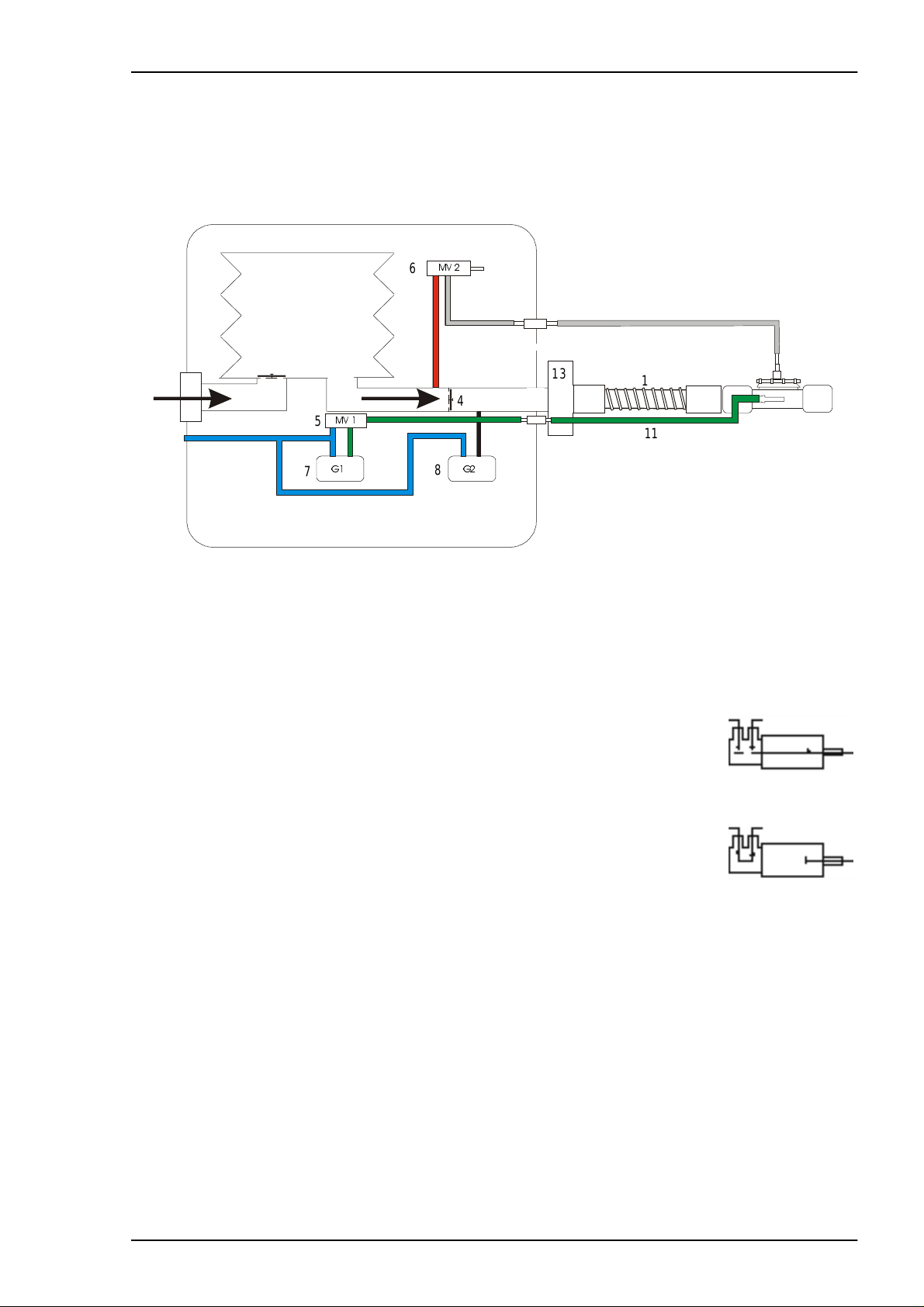
5.1 Pneumatic diag ram
PV 401 -2
6
2
3
1
5
Blue
Blue
7
Green
Blue
Grey/Tra nsparent
Red
4
Black
8
13
Green
9
10
11
12
Fig. 5-1 Pneumatic drawing
1. Patient air in let (t hrough air filte r)
2. Bellows
3. C heck valve (c los ed during inspiration)
4. C heck valve (c los ed during expiration)
5. Magnetic v alv e MV 1 (Normally set as in (1) .
Switches during autocalibration off G1 according to (2).)
6. Magnetic v alv e MV 2 (Normally set as in (2) .
Safety v alv e that switch es at to o high pressu re according
to (2).)
7. Pressure senso r G1
8. Pressure senso r G2
9. Control pressure tube for the expiration valve
10. Patient air t ube
11. Tube for meas uring the pres s ure
12. Expirat ion valve
13. Bacter ia f ilt er (if used)
1
2
Doc. No. 1527En Issue: M-2 BREAS MEDICAL 5 – 1
FUNCTIONAL DIAGRAMS Service Manual PV 401-2
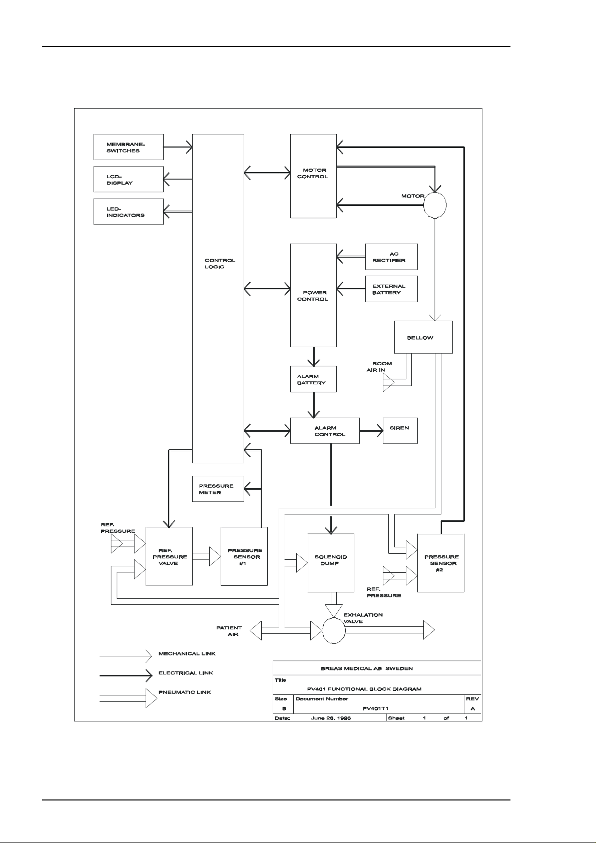
5.2 Functional block diagram
Fig. 8-2 Functional block dia gram
5 – 2 BREAS MEDICAL Doc. No. 1527En Issue: M-2
Service Manual PV 401-2 REMOVING/ REPLACI NG THE M AIN COM PO NE NTS
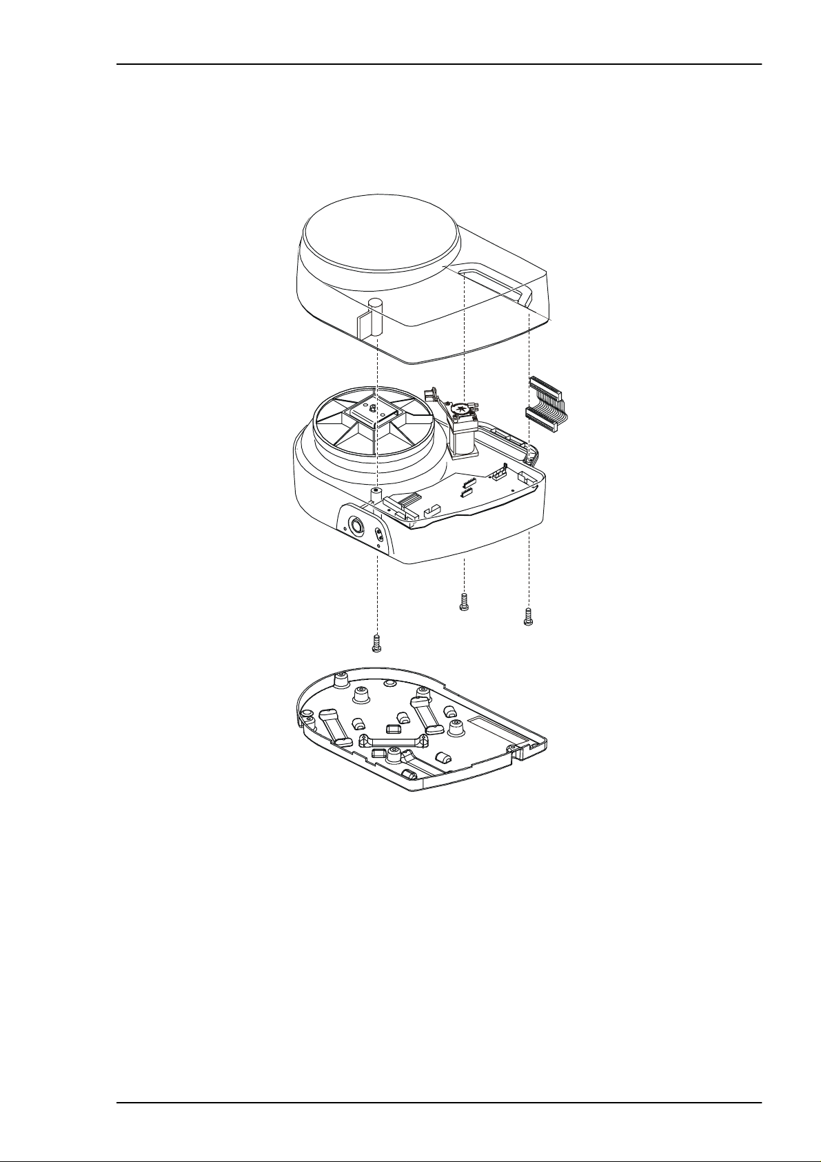
6 REMOVING/REPLACING THE MAIN COMPONENTS
6.1 Removing the upper casing
Fig. 6-1 Removing the upper casing
• Remove the power cord.
• Remove the two M4 sc rews (TX20 head) from un der the carrying handle and th e
screw fr om underneath t he ventilator at t he front.
• Lift up the upper casing and disconnect the ribbon cable from the CPU board. Put the
casing to one side.
Doc. No. 1527En Issue: M-2 BREAS MEDICAL 6 – 1
REMOVING/REPLACIN G THE MAIN CO MPONEN T S Service Manual PV 401-2
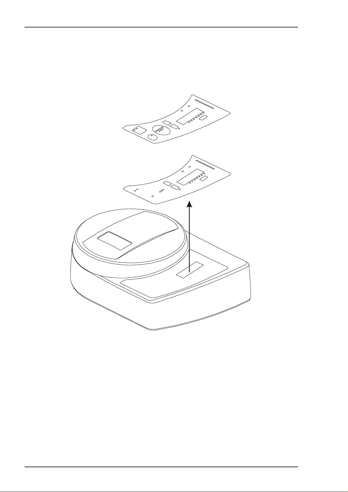
6.2 Removing/replacing the pushbutton membrane panel
• Remove the upper ca s ing (see Section 6.1).
• Remove the CPU board (see Section 6.3).
• If still connected, disconnect the ribbon cable f rom t he CPU board .
Fig. 6-2 Removing the deca l and pushbut to n board
• Start to loosen the pushbutton pa nel and decal as one unit by caref ully prising it up
from und erneath the o pening in the ca s ing for the LCD dis play. Continue to carefully
work the panel up until it ca n be removed .
• Reassem ble in the rev ers e order.
6 – 2 BREAS MEDICAL Doc. No. 1527En Issue: M-2
Service Manual PV 401-2 REMOVING/ REPLACI NG THE M AIN COM PO NE NTS
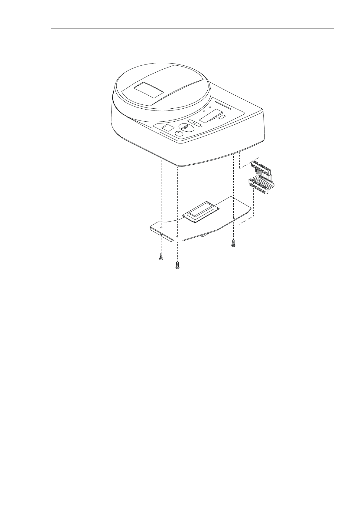
6.3 Removing/replacing the CPU board
Fig. 6-3 Remo vi ng the CPU board from the upper casing
• Remove the upper c as ing (see Section 6.1).
• Disconnect the ribbon cable from t he pushbutton membra ne board.
• Remove the three sc rew s holding the C PU board and re m ov e the board.
• Loosen the LCD board from its strip connector and the two plastic supports.
• Reassemble the ne w board in the rev ers e order.
Important! When replacing the CPU board, th e so ftwa re mu st be programmed for
if an inte rnal battery is in s ta lled or not, and if the battery relay K2 is
fitted on the MDA board or not. See “Programming the software” for
more inf ormation.
Doc. No. 1527En Issue: M-2 BREAS MEDICAL 6 – 3
REMOVING/REPLACIN G THE MAIN CO MPONEN T S Service Manual PV 401-2
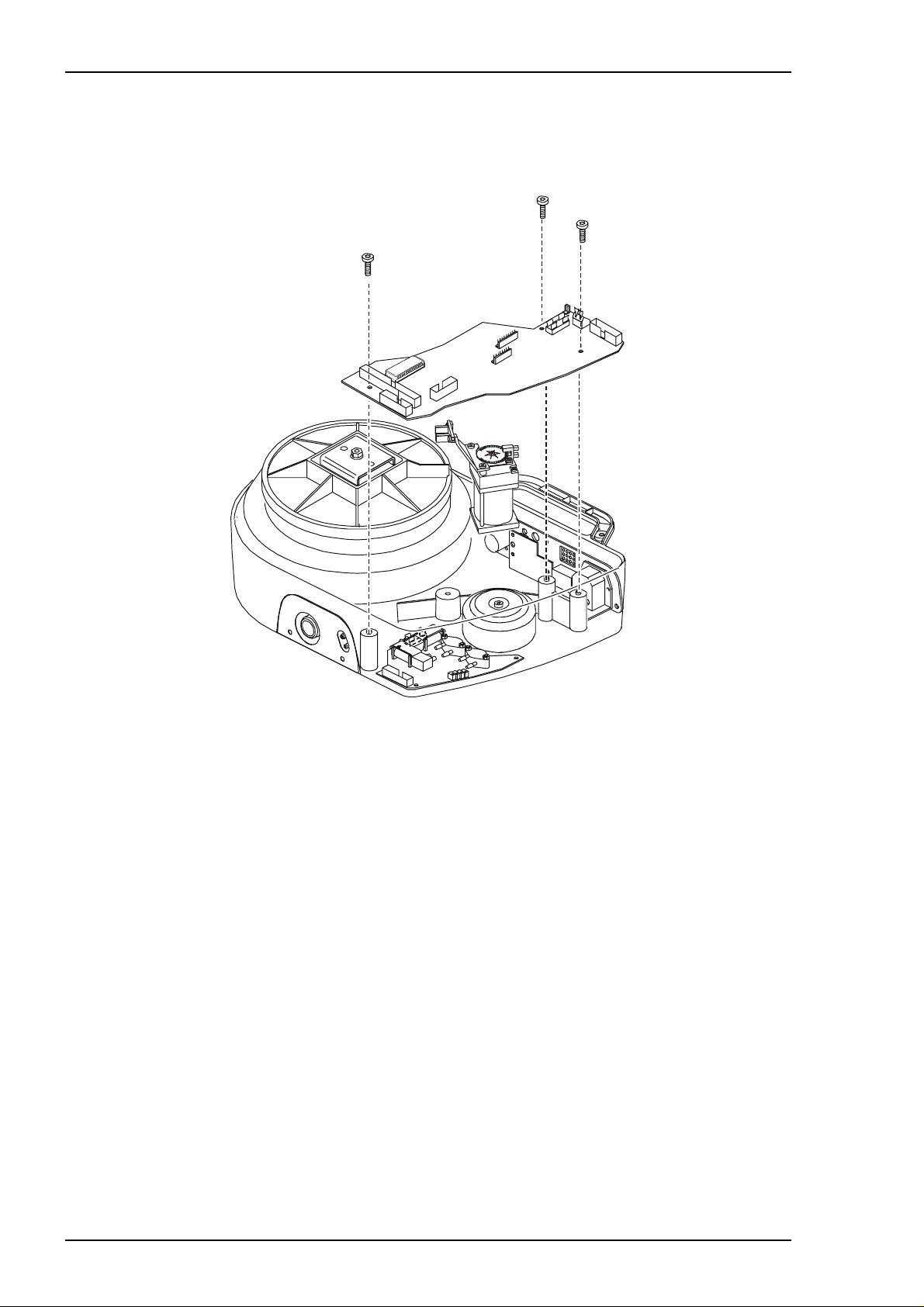
6.4 Removing/replacing the MDA board
• Remove the upper ca s ing (see Section 6.1).
Fig. 6-4 Removing the MDA Board
• Disconnect all the ribbon cable connectors, the external battery connector from CN4,
and the wires to the transformer.
• Remove the three sc rew s t hat hold the MDA board.
• Lift out the MDA board.
• Reassem ble the new board in the reve rs e order.
Important! When replacing the CPU board, the software must be programmed for
if an inter nal battery is inst alled or not, an d if th e battery relay K2 is
fitted o n the M DA bo ard or n ot. See “Programm ing the software ” for
more information.
6 – 4 BREAS MEDICAL Doc. No. 1527En Issue: M-2