

Breas Medical PV401 Service manual

TABLE OF CONTENTS Service Manual PV401
TABLE OF CONTENTS
1. INTRODUCTION.....................................................................................................1
1.1 Intended use of t he ventilator................................................................................ 1
1.2 Design and funct ion of the ventilator..................................................................... 1
1.3 The scope of this manual...................................................................................... 1
1.4 Intended audience ................................................................................................1
1.5 Serv ice personnel's trai ning requirements............................................................. 1
2. OPERATING MANUAL (Reference copy)
3. MAINTENANCE SERVICE INSTRUCTIONS..........................................................1
3.1 Verifying the components and software installed................................................... 1
3.2 Special safety precautions.................................................................................... 1
3.3 Equipment and tools required ...............................................................................1
3.4 Replacement parts required.................................................................................. 1
3.5 Servicing instructions............................................................................................2
3.6 Serv ice schedule..................................................................................................2
3.7 External checks .................................................................................................... 3
3.8 Internal checks..................................................................................................... 4
3.9 Final c hec k s before handing over......................................................................... 6
4. REPLACEMENT PARTS.........................................................................................1
4.1 General view ........................................................................................................1
4.2 Casings and decals............................................................................................... 2
4.3 Drive unit.............................................................................................................. 3
4.4 Exploded view A, M otor and Transformer............................................................. 4
4.5 Exploded view B, Casi ng and B ase Plate ............................................................. 5
4.6 Exploded view C, Circuit B oar ds and Connect or s .................................................6
4.7 Exploded view D,.B ellows and Driv e Screw.......................................................... 7
4.8 Part No. list...........................................................................................................8
5. FUNCTIONAL DIAGRAMS
5.1 Pneumatic Diagram.............................................................................................. 1
5.2 Functional Block Diagram..................................................................................... 2
6. DISMANTLING AND ASSEMBLING THE PV 401 ..................................................1
6.1 Tools required....................................................................................................... 1
6.2 Removing the upper casi ng ..................................................................................1
6.3 Replacing t he LCD boar d...................................................................................... 2
6.4 Removing the motor unit from the lower casing.................................................... 3
6.5 Replacing t he c omplete motor unit ........................................................................ 4
6.6 Assembling the motor unit in the casing................................................................ 6
7. MOTOR UNIT..........................................................................................................1
7.1 Construction ......................................................................................................... 1
7.2 Inspecting/Replacing the drive belts...................................................................... 2
7.3 Lubricating the drive screw................................................................................... 2
7.4 Replacing t he membranes in the check valves..................................................... 3
7.5 Tubes and bellows, leakage chec k........................................................................ 6
7.6 Replacing t he dr ive screw assembl y .....................................................................7
Doc. No.1525En Issue: K-2 BREAS MEDICAL Page 1

Service Manual PV401
8. ELECTRONICS ......................................................................................................1
8.1 Function and c onstr uc tion......................................................................................1
8.2 Wiring diagram, test points....................................................................................6
8.3 Main cabling diagram............................................................................................7
8.4 Test points.............................................................................................................8
8.5 Calibration of pressure sensors..............................................................................9
8.6 Check of bat tery operation................................................................................... 11
8.7 Replacing t he alarm batteries..............................................................................12
8.8 Electrical safety precautions................................................................................14
8.9 Upgrading the sof tware........................................................................................15
8.10 Upgrading the sof tware to revision MXG.............................................................. 16
8.10 Circuit diagrams..................................................................................................18
8.11 Component posit ions...........................................................................................28
8.12 Component l ist....................................................................................................33
9. FAULT TRACING ...................................................................................................1
9.1 Fault tracing..........................................................................................................1
9.2 Error codes............................................................................................................3
10. APPENDICES
10.1 Engineering Change History PV 401......................................................................1
10.2 Service Record For PV 401...................................................................................1
10.3 Returning Produc ts To Breas.................................................................................1
10.4 Breas Addresses...................................................................................................1
Page 2 BREAS MEDICAL Doc. No. 1525En Issue: K-2

Service Manual PV 401 INTRODUCTION
1 INTRODUCTION
1.1 Intended use of the ventilator
The PV 401 is a pressure-controlled, pressure-monitored ventilator, especially developed
for treatment in the home of patients with chronic breathing difficulties.
The PV 401 is designed to give many years of trouble-free breathing assistance to the
user provided that preventive maintenance is done at the specified intervals described in
this manual.
Well-performed maintenance will increase the service life of t he ventila tor conside rably. It
is also important that any peripheral equipment and accessories are checked at the time
the service is carried out.
1.2 Design and function of the ventilator
The PV 401 is constructed around a bellows and a drive screw assembly driven
by an electronically-controlled servo-motor. A microprocessor controls the correct
speed of the motor and its power supply by means of calculations based on the
settings for pressure, rate, inspiration time etc. The set pressure and the trigger
level are monitored at the same time.
In the event of a mains power supply fail, the ventilator will automatica lly swit ch to
the external battery supply. This is indicated by the LED in the On/Off button
flashing. If the external battery voltage drops too low, an audible alarm is given.
1.3 The scope of this manual
The manual contains all the points to be checked during the maintenance service
and other service instructions for the PV 401. Also included are reference copies
of the Operating Manual and the Patient Data Analysis Manual.
1.4 Intended audience
This Service Manual is intended for technicians who have medical/technical training and
knowledge of the construction and function of the ventilator.
It is not intended for clinic personnel or patients.
Breas Medical reserves the right to make changes to the product and the contents of this
manual without prior notice.
1.5 Service personnel's training requirements
Thanks to the simple construction of the PV 401, no special competence is
required other than general medical technical training on ventilators.
Always contact Breas Medical if there are any questions or if training is required.
All service must, however, be performed as described in this manual.
Doc. No. 1525En Issue: K-2
BREAS MEDICAL Page 1

INTRODUCTION Service Manual PV 401
Page 2 BREAS MEDICAL
Doc. No. 1525En Issue: K-2

Operating Manual
PV 401


Operating Manual PV 401
CONTENTS
1 INTRODUCTION.......................................................................................................1
2 IMPORTANT SAFETY NOTICES.............................................................................2
3 INSTALLATION........................................................................................................3
3.1 Unpacking.....................................................................................................................3
3.2 Placement.....................................................................................................................3
3.3 Connecting the tubes...................................................................................................3
3.4 Mains power supply.....................................................................................................3
3.5 Replacing the fuse........................................................................................................4
3.6 Power cord....................................................................................................................4
3.7 External battery power.................................................................................................4
4 PANEL DESCRIPTIONS...........................................................................................5
4.1 Front panel....................................................................................................................5
4.2 Setting panel description.............................................................................................6
4.3 Rear panel description.................................................................................................7
4.4 Underside description..................................................................................................8
5 DETAILED FUNCTION DESCRIPTION....................................................................9
5.1 On/Off button and External battery operation............................................................9
5.2 Checking the software version....................................................................................9
5.3 Function button............................................................................................................9
5.4 Decrease/Increase and Selection buttons.................................................................10
5.5 Lock function..............................................................................................................10
5.6 Setting Date and Time................................................................................................10
5.7 Alarms.........................................................................................................................11
5.8 PCV & PSV Modes......................................................................................................12
5.8.1 PCV (Pressure Control Ventilation) Mode...................................................................12
5.8.2 PSV (Pressure Support Ventilation) Mode...................................................................13
5.8.3 Comparing PCV and PSV.............................................................................................14
5.9 Settings.......................................................................................................................15
5.9.1 Setting a parameter value............................................................................................15
5.9.2 Pressure........................................................................................................................15
5.9.3 Alarm for low Pressure.................................................................................................15
5.9.3.1 Setting the alarm level for Pressure................................................................16
5.9.4 Rate...............................................................................................................................16
5.9.5Inspiration time.............................................................................................................17
5.9.6 Trigger...........................................................................................................................17
5.9.7 Plateau..........................................................................................................................18
5.9.8 Expiratory sense (EXP. SENSE)...................................................................................18
5.9.9Tidal volume (Est. Vol.)................................................................................................19
5.9.10Alarm for low Tidal Volume..........................................................................................19
5.9.10.1 Setting the alarm level for low Tidal Volume................................................19
5.10 Incorrect settings.......................................................................................................20
5.11 Digital Output (D-sub, female)...................................................................................20
5.12 Analog Output (D-sub, male).....................................................................................21
BREAS MEDICAL
Doc. No. 1602EN Issue: M-1

Operating Manual PV 401
6 FUNCTION CHECKS.............................................................................................22
6.1 Function check in PSV (Pressure Support Ventilation) mode..................................22
6.1.1 Alarm check “PATIENT” – low Pressure......................................................................22
6.1.2 Inspiration.....................................................................................................................23
6.1.3 Exhalation.....................................................................................................................23
6.1.4 Trigger...........................................................................................................................23
6.1.5 Expiratory sense (EXP. SENSE)...................................................................................23
6.1.6 Tidal volume (EST. VOL.).............................................................................................23
6.1.7 Alarm check for low Tidal Volume...............................................................................24
6.1.8 Alarm check for Power failure......................................................................................24
6.1.9 Completing the function check....................................................................................24
6.2 Function check in PCV (Pressure Control Ventilation) mode..................................24
6.2.1 Alarm check PATIENT – low pressure.........................................................................25
6.2.2 Inspiration.....................................................................................................................26
6.2.3 Exhalation.....................................................................................................................26
6.2.4 Trigger...........................................................................................................................26
6.2.5 Tidal volume (EST. VOL.).............................................................................................26
6.2.6 Alarm check for low Tidal volume...............................................................................26
6.2.7 Alarm check POWER....................................................................................................27
6.2.8 Completing the function check....................................................................................27
7 USAGE...................................................................................................................28
7.1 Adjustment of the mask and patient circuit...............................................................28
7.2 Settings in PSV mode.................................................................................................28
7.3 Settings in PCV mode.................................................................................................28
8 BATTERY OPERATION.........................................................................................29
8.1 External Battery...........................................................................................................29
8.2 Low battery voltage alarm..........................................................................................29
9 OXYGEN CONNECTOR.........................................................................................30
10 CLEANING, FILTER REPLACEMENT AND SERVICE..........................................31
10.1 Cleaning/replacing the air filter..................................................................................31
10.2 Yearly service..............................................................................................................31
11 FAULT TRACING...................................................................................................32
11.1 Fault tracing chart.......................................................................................................32
12 ACCESSORIES......................................................................................................33
13 TECHNICAL SPECIFICATIONS PV 401................................................................34
14 PNEUMATIC DIAGRAM.........................................................................................35
15 PATIENT INSTRUCTIONS FOR BREAS PERSONAL VENTILATOR PV 401......36
PATIENT SETTINGS....................................................................................................37
Doc. No. 1602EN Issue: M-1
BREAS MEDICAL
Operating manual PV 401 INTRODUCTION
1 INTRODUCTION
The PV 401 is a pressure controlled and pressure support ventilator.
It has two modes of operation; PSV and PCV. Both modes have an adjustable trigger
sensitivity setting which allows the patient to initiate ventilator-assisted breaths.
In PSV mode (Pressure Support Ventilation), the ventilator’s expiratory sense can also be
adjusted allowing the ventilator to more easily match each patient's needs.
In PCV mode (Pressure Controlled Ventilation) the ventilator provides assisted/controlled
breathing.
Explanation of label symbols under the ventilator:
Read the Operating Manual thoroughly before connection to the patient.
0 1 2 3
Body floating.
Class II equipment; dual isolation.
CE marking applies according to the directive MDD 93/42/EEC.
TÜV approved according to IEC 601-1, EN 794-2.
Doc. No. 1602EN Issue: M-1
BREAS MEDICAL Page 1

IMPORTANT SAFETY NOTICES Operating manual PV 401
2 IMPORTANT SAFETY NOTICES
The PV 401 should not be used for total life support. Use BREAS PV 501 instead.
•
Clinic personnel and patients must read this operating manual and understand how the
•
PV 401 works before setting up and using the ventilator.
Adjustments to settings may only be carried out by authorised clinic personnel.
•
Before use, a function check must be performed.
•
To ensure maximum operational reliability, the PV 401 must be serviced at the specified
•
intervals by authorised service personnel.
Oxygen may only be supplied through the patient hose, use BREAS oxygen adapter.
•
Do not use the PV 401 in environments where there are explosive gases or other
•
inflammable anaesthetic agents present.
Do not use patient hoses or tubes made of static or electrically conducting material.
•
Electromagnetic fields greater than 10 V/m can affect operation. Examples of equipment
•
that produce electromagnetic fields are defibrillators, diathermia equipment, cellular
telephones, etc.
Do not use a steam autoc lave to sterilise the vent ilat or.
•
The ventilator’s performance may deteriorate at temperatures below 5°C and above
•
50°C.
Do not place the PV 401 on soft surfaces so that the air inlet on the underside can be
•
blocked.
Always clean all parts that come in contact with the exhalation air before use on a new
•
patient.
If an air humidifier is used, always place it
•
lower
than the PV401 to prevent water from
running into the ventilator if the humidifier tips over.
Page 2 BREAS MEDICAL
Doc. No. 1602EN Issue: M-1
Operating manual PV 401 INSTALLATION
3 INSTALLATION
3.1 Unpacking
Check the ventilator for any damage and that all ordered accessories are included.
•
3.2 Placement
Place the PV 401 on its feet, on a hard, flat surface. Make sure that nothing can block
•
the patient air inlet under the ventilator.
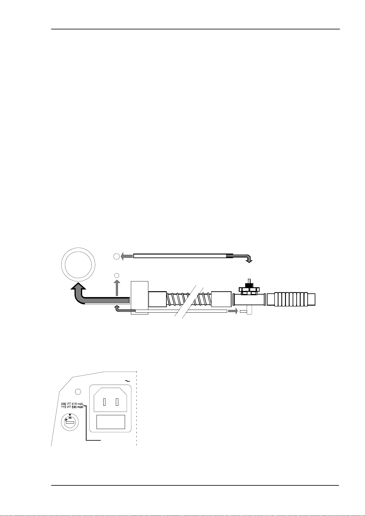
3.3 Connecting the tubes
Connect the patient circuit (A) to the “PATIENT AIR” outlet on the front panel.
•
Connect the thin tube (B) for the exhalation valve to the “EXH. VALVE” nipple.
•
Connect the pressure measuring tube (green) (C) to the “PRESSURE” connector.
•
If a bacteria filter/oxygen adapter (D) is used, connect it between hose (A) and the
•
patient air outlet.
PATIENT AIR
Exh. Valve
Pressure
D
B
A
C
3.4 Mains power supply
IMPORTANT! Make sure that the power cord is undamaged before it is connected to the
•
ventilator.
Check that the voltage selector is set for the voltage the
POWER SUPPLY
POWER
•
ventilator is to be connected to. Different countries have
different power supplies, the USA has, for example 115 V.
All European countries have 230 V.
Voltage range 115 V covers 110 – 120 V
Voltage range 230 V covers 220 – 240 V
To change the voltage setting
Make sure the power cord is
POWER
Doc. No. 1602EN Issue: M-1
•
Change by turning with a screwdriver.
•
Change to the correct fuse rating.
•
connected.
not
BREAS MEDICAL Page 3
INSTALLATION Operating manual PV 401
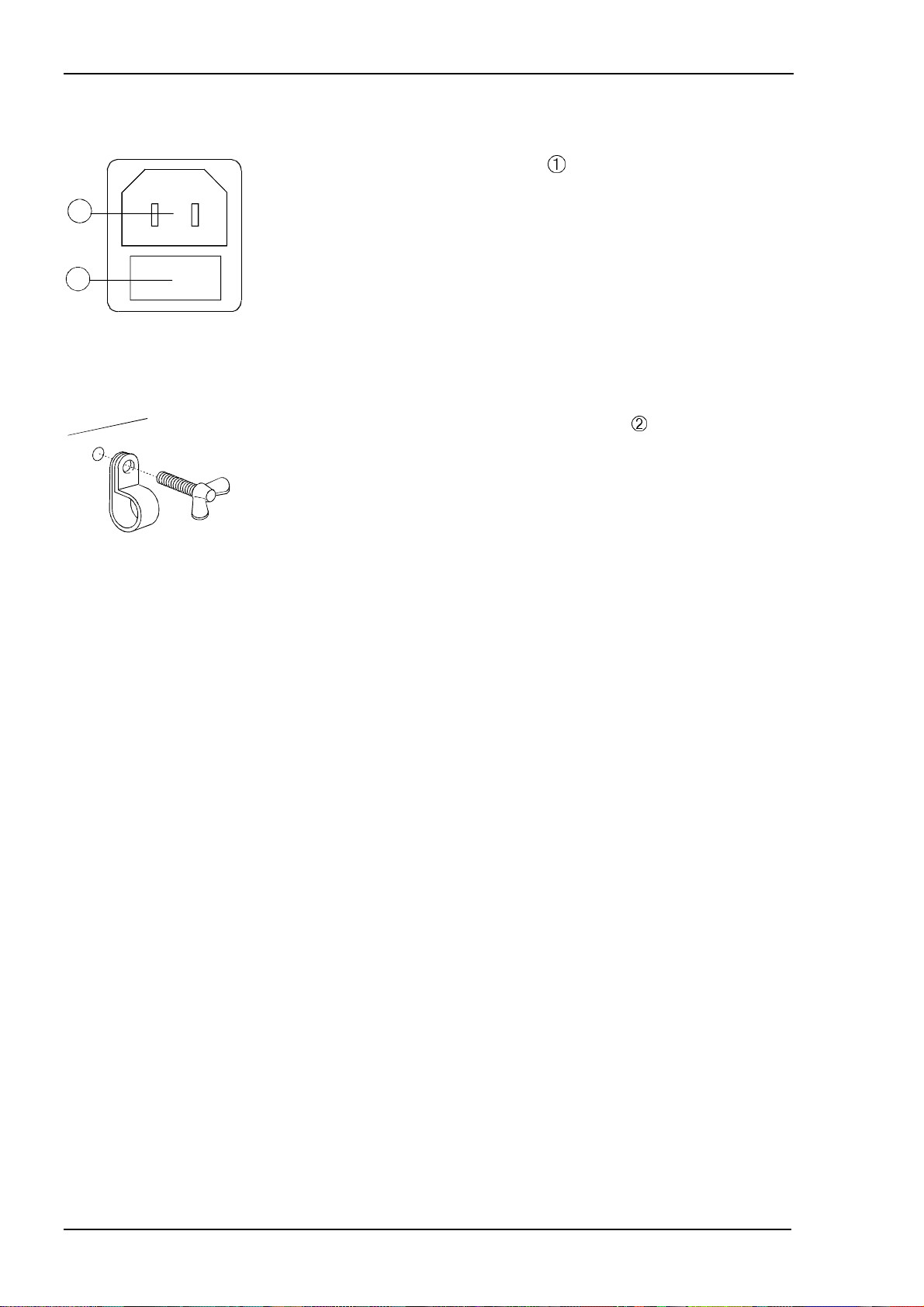
3.5 Replacing the fuse
Check that the power supply fuse
•
the set voltage.
2
For 230 V, use a glass fuse F 315 mAL
For 115 V, use a glass fuse F 630 mAL
1
3.6 Power cord
3.7 External battery power
Change the fuse by pulling the fuse holder straight out.
•
There is a spare fuse in the holder.
Connect the power cord to the power socket
•
BREAS power cord.
Secure the power cord in the clip to prevent accidental
•
disconnection.
has the correct rating for
. Only use a
See Chapter 8 for complete information.
Page 4 BREAS MEDICAL
Doc. No. 1602EN Issue: M-1

Operating manual PV 401 PANEL DESCRIPTIONS
4 PANEL DESCRIPTIONS
4.1 Front panel
PATIENT AIR
EXH.
VALVE
PRESSURE
1
(1) Patient air outlet, ∅ 22 mm ISO cone, male.
(2) Exhalation valve connector, ∅ 4 mm tube.
(3) Connector for pressure measuring at the exhalation valve, ∅ 3 mm tube (green).
2 3
Doc. No. 1602EN Issue: M-1
BREAS MEDICAL Page 5
PANEL DESCRIPTIONS Operating manual PV 401
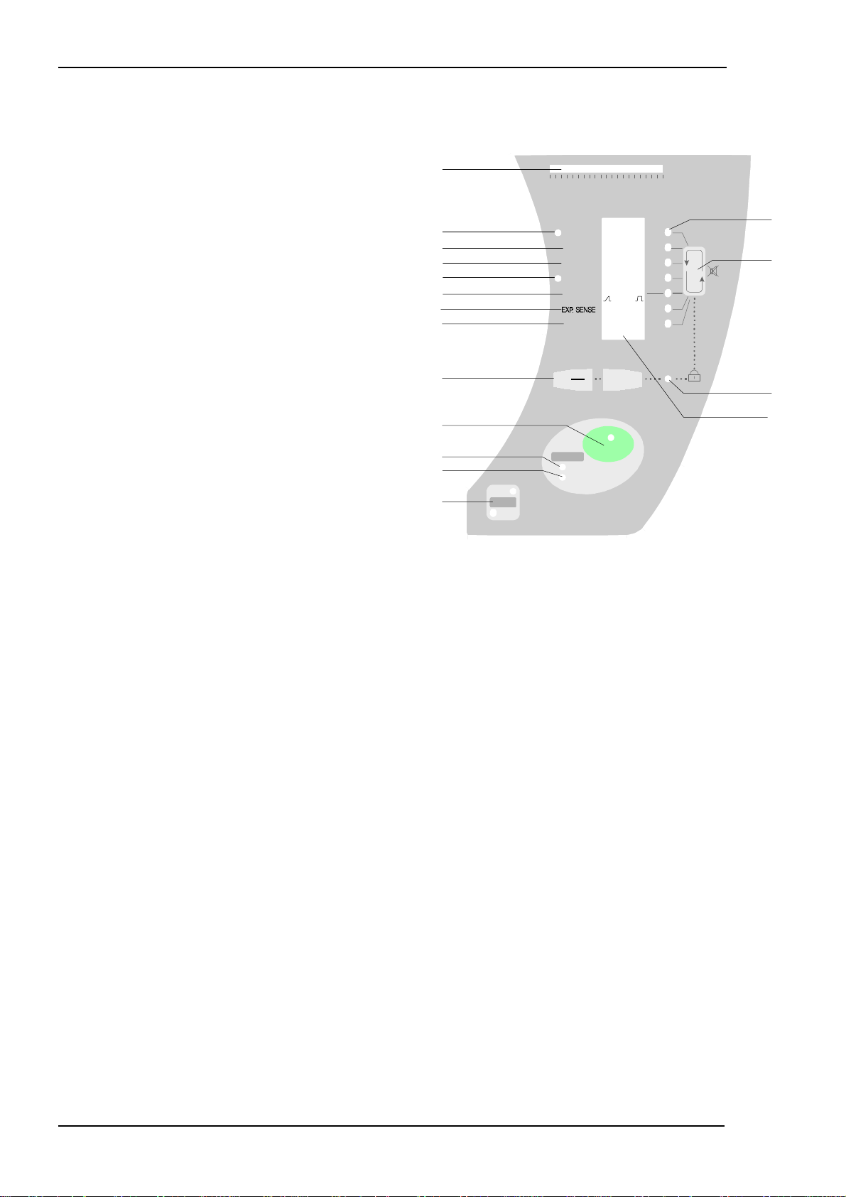
4.2 Setting panel description
(1) Patient pressure meter;
0 to 40 mbar/cm H
O.
2
(2) Patient pressure setting;
Green LED is lit during inspiration.
(3) Rate setting;
Breaths per minute (BPM).
(4) Inspiration time setting; in seconds
(only active in PCV mode.)
(5) Trigger setting; green LED is lit during a
patient triggered inspiration.
(6) Plateau setting; the time to reach
the set pressure.
(7) Expiratory sense setting; percentage of
maximum flow. (Only active in PSV mode.)
(8) Est. Vol. The tidal volume delivered is
displayed here after each breath.
The alarm level setting function for Pressure
and low Tidal Volume is also accessed here.
10
11
12
13
1
2
3
4
5
6
7
8
9
PRESSURE
010203040
mbar / cm HO
2
PRESSURE
RATE.
.INSP. TIME
TRIGGER
PLATEAU
EST. VOL.
6
6
0.5
OFF,-2
10
0
mbar
40
BPM
40
Sec
5
mbar
8
%
80
Liter
1.8
+
14
15
16
17
PSV
MODE
PCV
ALARM
POWER
PATIENT
ON/OFF
(9) - and + buttons to increase or decrease the selected parameter. The buttons are also
used to set the date and time and to make selections in different displays.
(10) ON / OFF switch; Keep pressed for 2 seconds to start or stop the ventilator.
(11) Alarm for power failure; red LED lights if the mains or external battery supply fails.
An audible alarm is also given.
(12) Patient alarm. The red LED flashes if the set percentage of the set pressure is not
reached within 15 seconds, e.g. due to leakage from the mask and/or the tidal
volume is low. An audible alarm is also given together with a flashing arrow
indication against the function in question (Pressure and/or Est. Vol) in the display.
(13) Button for changing between PSV (Pressure Support Ventilation) and
PCV (Pressure Control Ventilation) mode. Keep pressed for 1 second to change
mode.
(14) Seven LED indicators showing which function is selected. The selection function's
parameter can be adjusted using the –/+ buttons (9).
(15) Function button. Used to select required parameter or to mute audible alarms for
2 minutes.
(16) Green LED, when lit, indicates that the setting panel is locked.
(17) LCD Display. Shows the current settings. It is also used when setting the Date & Time.
The background lights when button (15) is pressed and stays on for 2 minutes after the
last press on a setting button.
Page 6 BREAS MEDICAL
Doc. No. 1602EN Issue: M-1
Operating manual PV 401 PANEL DESCRIPTIONS
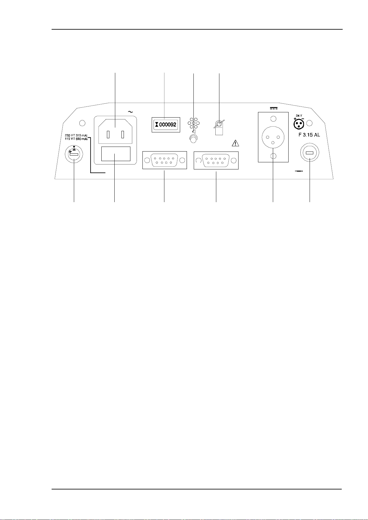
4.3 Rear panel description
1
POWER SUPPLY
POWER
ANALOG OUTPUT
FUSE
5 6 7
(1) Connection for power cord.
2 3
OPERATION HOURS
4
DIGITAL OUTPUT
EXT. BATTERY FUSE
8 9
10
(2) Hour meter, shows the ventilator's total operation time.
(3) Buzzer for alarm. Adjust the sound level using a small screwdriver.
(4) Fastening clamp for power cord.
(5) Voltage selector switch; 115 V or 230 V AC.
(6) Fuse holder with fuse, T 630 mA for 115 V, T 315 mA for 230 V.
(7) Analog signal output for registering patient pressure and tidal volume, male.
(8) Digital communication connector, female.
(9) Socket for external battery, 24V DC.
(10) Fuse holder with fuse for external battery supply. F 3.15 A.
Doc. No. 1602EN Issue: M-1
BREAS MEDICAL Page 7

PANEL DESCRIPTIONS Operating manual PV 401
4.4 Underside description
2
1
(1) Air inlet and filter for patient air. See Chapter 10 for replacing/cleaning the filter.
(2) Model and serial number label.
Explanation of symbols on label:
1
2
3
4
5
67
(1) Model number.
(2) Serial number.
(3) Class II equipment; dual isolation.
(4) Body floating.
(5) Read the Operating Manual thoroughly before using with the patient.
(6) CE marking applies according to the directive MDD 93/42/EEC.
(7) TÜV approved according to IEC 601-1, EN 794-2.
Page 8 BREAS MEDICAL
Doc. No. 1602EN Issue: M-1

Operating manual PV 401 DETAILED FUNCTION DESCRIPTION
5 DETAILED FUNCTION DESCRIPTION
5.1 On/Off button and External battery operation
The green LED shows a steady light when the ventilator is operating from
ON/OFF
The ventilator should be kept connected to the mains supply, even when not in use, to
maintain charging of the alarm batteries.
5.2 Checking the software version
PRESSURE
RATE
INSP. TIME
TRIGGER
PLATEAU:
EST. VOL.
REV
401
MXG
the mains supply. The LED flashes when operating from an external battery.
Press and hold the button for 2 seconds to switch on or off.
When switching on the ventilator, the software version installed
mbar
BPM
sec
mbar
SGP
%
Liter
is shown for approx. 1 second before the ventilator starts
working.
The illustration shows an example of how the software version
designation can appear.
5.3 Function button
This button is used to:
Select the parameter to be adjusted
This button is used to select the required parameter to be
set. A lit green LED indicates which parameter is active. If no
setting is done within 5 seconds, the selected parameter LED
will go off.
Mute the acoustic alarm
This button is also used to mute acoustic alarms for two minutes.
PRESSURE
RATE
INSP. TIME
TRIGGER
PLATEAU:
EST. VOL.
Y 97
M 12
D 07
H 13
M 34
mbar
BPM
sec
mbar
%
Liter
Pressing the function button will light the background illumination of the display.
Select Date & Time
If this button is held while switching on the ventilator, the current
date & time is shown in the display. See section 5.6, Setting
Date and Time, for more information
Doc. No. 1602EN Issue: M-1
BREAS MEDICAL Page 9

DETAILED FUNCTION DESCRIPTION Operating manual PV 401
5.4 Decrease/Increase and Selection buttons
These buttons have two functions.
+
They are used to adjust a parameter setting, press
to
–
decrease or + to increase the value of the selected
parameter. The new setting is saved in the ventilator’s
memory at the first breath after the value has been set.
The buttons are also used to set the date and time and as
Yes/No selection buttons when setting the alarm levels for
pressure and tidal volume, where
+ = Yes and - = No.
5.5 Lock function
1
The lock function is used to lock the setting panel to prevent
accidental changes to the settings.
+
When the LED
is on, the lock is active. It is now only
possible to switch the ventilator On or Off.
Press and hold both the
and
–
buttons for 5 seconds to
+
lock or unlock.
5.6 Setting Date and Time
As part of the data storage function, the date and time is recorded to allow analysis of the
patient data in the different printouts available.
Note! The clock function uses the 24-hour clock standard.
To check or set the date and time:
Press and hold the Function button while pressing the
•
PRESSURE
RATE
INSP. TIME
TRIGGER
PLATEAU:
EST. VOL.
Y 97
M 12
D 07
H 13
M 34
mbar
BPM
sec
mbar
%
Liter
On/Off button.
The display will now show the current settings for date and
time.
To change a setting:
Press the Function button until the LED for the
•
required setting is lit.
Press + to increase the setting or - to decrease it.
•
Continue by moving down through the menu to the
•
M setting.
To exit this display, press the Function key after
•
the M setting has been selected.
Page 10 BREAS MEDICAL
Doc. No. 1602EN Issue: M-1

Operating manual PV 401 DETAILED FUNCTION DESCRIPTION
The display will now show the following text.
Switch off the ventilator.
PRESSURE
RATE
INSP. TIME
TRIGGER
PLATEAU:
EST. VOL.
TURN
OFF
POWER
mbar
BPM
sec
mbar
%
Liter
•
The new date and/or time will be saved.
5.7
Alarms
Power (red LED)
Should the power supply fail during operation, the ventilator will
ALARM
POWER
PATIENT
alarm by the red LED for “POWER” being lit and an audible alarm.
Attempts to start the ventilator without any power source
connected will also cause this alarm.
Patient (red LED)
The patient alarm (red LED) flashes if the set percentage of the
ALARM
POWER
PATIENT
set pressure is not reached within 15 seconds, e.g. due to leakage
from the mask and/or the tidal volume is low. An audible alarm is
also given together with a flashing arrow indication against the
function (Pressure and/or Est. Vol) in the display.
The alarm is reset once the pressure and/or the tidal volume reaches
the set value.
Alarm for low Pressure
The alarm for low pressure can be set as required. Refer to section 5.9.3, Alarm for low
Pressure, for information.
Alarm for low Tidal Volume
The alarm for low Tidal Volume can be set as required. Refer to section 5.9.10, Alarm
for low Tidal Volume, for information.
Alarm mute
The alarm can be muted for 2 minutes by pressing the Function
(alarm mute) button.
The alarm for low tidal volume can also be adjusted, see 5.7.7.
Alarm sound level
Adjust the sound level of the alarm to a suitable level. Adjust the screw
(
in figure) on the ventilator’s rear panel using a small screwdriver.
1
Doc. No. 1602EN Issue: M-1
BREAS MEDICAL Page 11

DETAILED FUNCTION DESCRIPTION Operating manual PV 401
5.8 PCV & PSV Modes
This section describes the PCV and PSV modes. The ventilator always starts in the mode
which was active when it was switched off.
To change between PSV and PCV mode, press the MODE button for one
PSV
MODE
PCV
5.8.1 PCV (Pressure Control Ventilation) Mode
•
second.
In
mode, the ventilation is controlled by the ventilator. The RATE setting corresponds to
PCV
the patient’s breathing rate expressed as the number of breaths per minute (BPM). The length
of each inspiration is controlled by the INSPIRATION TIME setting. The PLATEAU parameter
sets the speed at which the pressure increases to the set value. The lower the setting, the
slower the pressure increase will be, a higher setting will give a faster pressure increase and
therefore a longer plateau.The setting has 9 steps where 1 is the lowest and 9 is the highest.
The figure below shows how the Pressure and Flow settings control the ventilator's
function in PCV mode, where the Pressure setting is 20 cm H
O, the Inspiration Time is
2
1.8 seconds and the Plateau setting is 5.
A breath is started when either the set rate starts a breath or the patient triggers a breath
(if trigger is activated). The ventilator tries to reach and maintain the set pressure until
either the inspiration time setting expires or the bellows reaches its end position.
Pressure
cm HO
2
20
Pressure setting
Plateau setting
Patient exhales
Start of breath
Flow
%
100%
Insp.time PCV
Max flow and set pressure is reached
Patient exhales
Page 12 BREAS MEDICAL
seconds
seconds
Doc. No. 1602EN Issue: M-1

Operating manual PV 401 DETAILED FUNCTION DESCRIPTION
5.8.2 PSV (Pressure Support Ventilation) Mode
In
PSV mode
and exhalation by the
ventilator’s
, the
patient
setting will take over where the RATE setting corresponds to the patient’s
rate
normally controls both inspiration through the
expiratory sense.
If the patient’s own “triggering” ceases, the
trigger function
,
breathing rate expressed as the number of breaths per minute (BPM).
The PLATEAU parameter sets the speed at which the pressure increases to the set
value. The lower the sett ing, the slower the pressure increase will be, a higher setting will
give a faster pressure increase. The setting has 9 steps where 1 is the lowest and 9 is
the highest.
The figure below shows how the Pressure and Plateau (Flow) settings control the
ventilator's function in PSV mode, where the Pressure setting is 20 cm H
O, the
2
Expiration Sense is 25% and the Plateau setting is 5.
A breath is started when either the patient triggers a breath (if trigger is activated) or the set
back-up Rate takes over. The ventilator tries to reach and maintain the set pressure until
either the flow drops to the “EXP.SENSE” setting (percentage of maximum insp. flow), the
bellows reaches its end position or Inspiration is longer than 3 seconds.
Pressure
cm HO
2
Pressure setting
20
Max. delivered pressure
Start of breath
EXP. Sense
setting
Flow
%
100%
25%
Patient exhales
Insp.time PSV
Max. flow
Flow has dropped to set EXP. Sense.
New breath is triggered
seconds
seconds
Doc. No. 1602EN Issue: M-1
BREAS MEDICAL Page 13

DETAILED FUNCTION DESCRIPTION Operating manual PV 401
5.8.3 Comparing PCV and PSV
The figure below shows the previous two examples superimposed to illustrate how the PCV
and PSV modes differ.
Pressure
cm HO
2
20
Flow
%
100%
25%
Insp.time PSV
Insp.time PCV
PSV
PCV
seconds
seconds
Page 14 BREAS MEDICAL
Doc. No. 1602EN Issue: M-1

Operating manual PV 401 DETAILED FUNCTION DESCRIPTION
5.9 Settings
This section describes the different parameters and how they are set, both in PSV and PCV
modes. Note! Certain parameters are not accessible in the PSV or PCV modes repectively.
5.9.1 Setting a parameter value
PRESSURE
RATE
INSP. TIME
TRIGGER
PLATEAU:
EST. VOL.
5.9.2 Pressure
PRESSURE
RATE
INSP.TIME
TRIGGER
PLATEAU
10
6
0.5
OFF,-2
15
10
1.8
-0.5
1. Press the Function button until the
required parameter is active.
The parameter is active for 5 seconds
after the last button has been pressed,
thereafter the parameter must be reselected in order to be adjusted.
2. Lit LED shows which parameter is active.
3. Adjust to the required setting with the
or + button.
–
The settings are saved at the next breath.
6
6
0.5
OFF,-2
10
0
+
15
10
1.8
-0.5
- X.X
40
40
80
1.8
mbar
BPM
5
mbar
8
sec
%
Liter
2
1
3
Lit LED indicates the selected parameter.
mbar
40
40
5
8
BPM
sec
mbar
Setting range: 6 to 40 mbar
Press
to decrease or + to increase the value of the
–
selected setting .
Pressure meter
PRESSURE
010203040
mbar / cm HO
2
Displays the pressure measured at the exhalation valve.
Range 0 to 40 mbar (cm H
2
O).
5.9.3 Alarm for low Pressure
The ventilator has a Pressure alarm function which is activated if the set percentage of the
pressure setting is not reached within 15 seconds, e.g. due to leakage from the mask.
Doc. No. 1602EN Issue: M-1
BREAS MEDICAL Page 15

DETAILED FUNCTION DESCRIPTION Operating manual PV 401
The alarm is given as:
ALARM
POWER
PATIENT
the red Patient LED flashing
•
an audible alarm
•
a flashing arrow indication shown against the Pressure field
•
in the display.
15
10
1.8
-0.5
40
40
5
8
mbar
BPM
sec
mbar
PRESSURE
RATE
INSP.TIME
TRIGGER
10
6
0.5
OFF,-2
The alarm is reset once the pressure reaches its set value again.
5.9.3.1 Setting the alarm level for Pressure
Make sure the setting panel is not locked.
PRESSURE
RATE
INSP. TIME
TRIGGER
PLATEAU:
EST. VOL.
A L A R M
S E T
NO YES
+
-
mbar
BPM
sec
mbar
%
Liter
•
Press the Function button until Est. Vol. is selected.
•
The display will change as shown in the figure.
Note! The alarm sett ing display will only be active for 5 seconds. If
no other button is pressed during this time the display will return
to standard display. Press the Function button once more to
return to the Alarm Setting function.
Select Yes by pressing the + button.
•
The display will now change as shown below.
Press the Function button to select the Pressure parameter.
•
65%
QUIT
+
1.40
mbar
BPM
sec
mbar
%
Liter
Adjust the setting using the - or + button as required (within
•
5 seconds).
To exit the alarm settings display, select the Trigger function
•
by pressing the Function button and then press the + button
(Quit). (Note! If required, the Tidal Volume alarm can also be
set before quitting).
The value is automatically saved when Quit is selected or the
PRESSURE
RATE
INSP. TIME
TRIGGER
PLATEAU:
EST. VOL.
display switches back to the standard setting display.
Note! If no other button is pressed within 5 seconds the display will return to standard display.
In this case, the entire alarm setting procedure must be repeated.
5.9.4 Rate
PRESSURE
RATE
INSP.TIME
TRIGGER
PLATEAU
10
6
0.5
OFF,-2
15
10
1.8
-0.5
40
40
5
8
mbar
BPM
sec
mbar
Lit LED indicates the selected parameter.
Setting range: 6 to 40 breaths per minute (BPM).
Press
to decrease, or + to increase the value of the
–
selected setting. The ventilator always gives the set number of
breaths, plus any triggered breaths.
Page 16 BREAS MEDICAL
Doc. No. 1602EN Issue: M-1

Operating manual PV 401 DETAILED FUNCTION DESCRIPTION
5.9.5 Inspiration time
PRESSURE
RATE
INSP.TIME
TRIGGER
PLATEAU
10
6
0.5
OFF,-2
15
10
1.8
-0.5
40
40
5
8
mbar
BPM
sec
mbar
Can only be selected in PCV mode.
Lit LED shows parameter selected.
Setting range: 0.5 – 5 seconds
Press
to decrease or + to increase the value of the selected
–
setting.
I/E Table
I/E Table
Table for calculating the I/E ratio based on inspirations time and rate
Breaths per minute (BPM)
6789101112 13 14 15 16 17 18 19 20 22 24 26 28 30 32 34 36 38
0.5 1:191:161:141:121:111:101:9 1:8 1:8 1:7 1:7 1:6 1:6 1:5 1:5 1:4 1:4 1:4 1:3 1:3 1:3 1:3 1:2 1:2
0.6 1:161:131:121:101:9 1:8 1:7 1:7 1:6 1:6 1:5 1:5 1:5 1:4 1:4 1:4 1:3 1:3 1:3 1:2 1:2 1:1.91:1.81:1.6
0.7 1:131:111:101:9 1:8 1:7 1:6 1:6 1:5 1:5 1:4 1:4 1:4 1:4 1:3 1:3 1:3 1:2 1:2 1:1.91:1.71:1.51:1.41:1.3
0.8 1:121:101:8 1:7 1:7 1:6 1:5 1:5 1:4 1:4 1:4 1:3 1:3 1:3 1:3 1:2 1:2 1:1.91:1.71:1.51:1.31:1.21:1.1
0.9 1:101:9 1:7 1:6 1:6 1:5 1:5 1:4 1:4 1:3 1:3 1:3 1:3 1:3 1:2 1:2 1:1.81:1.61:1.41:1.21:1.1
1.0 1:9 1:8 1:7 1:6 1:5 1:4 1:4 1:4 1:3 1:3 1:3 1:3 1:2 1:2.21:2 1:1.71:1.51:1.31:1.11:1.0
1.2 1:7 1:6 1:5 1:5 1:4 1:4 1:3 1:3 1:3 1:2 1:2 1:1.91:1.81:1.61:1.51:1.31:1.1
1.5 1:6 1:5 1:4 1:3 1:3 1:3 1:2 1:2 1:1.91:1.71:1.51:1.41:1.21:1.11:1.0
2.0 1:4 1:3 1:3 1:2 1:2 1:1.71:1.51:1.31:1.11:1.0
2.5 1:3 1:2 1:2 1:1.71:1.41:1.21:1.0
3.0 1:2 1:1.91:1.51:1.21:1.0
4.0 1:1.51:1.41:1.1
4.5 1:1.21:1.1
5.0 1:1.0
Example:Inspiration time is set to 1.5 seconds and rate to 12 breaths/minute.
This gives an I/E ratio of 1:2 (See markings in the table).
5.9.6 Trigger
RATE
INSP.TIME
TRIGGER
PLATEAU
6
0.5
OFF,-2
10
- -
-0.5
- -
40
5
8
BPM
sec
mbar
%
Lit LED shows parameter selected.
Setting range: Off / -2 to +8 mbar.
Press
to decrease or + to increase the value of the selected
–
setting.
When the patient starts a breath, a negative pressure is
created in the patient circuit which the ventilator registers
and immediately starts an inspiration.
Doc. No. 1602EN Issue: M-1
BREAS MEDICAL Page 17

DETAILED FUNCTION DESCRIPTION Operating manual PV 401
Choose a setting comfortable for the patient; normally between -0.2 to -0.5 mbar.
•
If the patient cannot trigger a breath, the ventilator automatically takes over and delivers
breaths according to the set rate. For each breath the patient triggers, the green LED
“TRIGGER” in the setting panel lights.
When the trigger is set to
the patient cannot trigger any extra breaths.
OFF,
The trigger can be set to positive values if an external PEEP valve is used.
Note! In the range 0 to +8 mbar there is a risk of the ventilator “self triggering”
5.9.7 Plateau
INSP. TIME
TRIGGER
PLATEAU:
EST. VOL.
0.5
OFF,-2
10
0
1.8
-0.5
- -
sec
5
mbar
8
%
80
Liter
1.8
Lit LED shows parameter selected.
PLATEAU sets the speed at which the set pressure increase
is reached.
A lower setting will give a slower pressure increase
and therefore a shorter plateau.
A higher setting will give a faster pressure increase
and therefore a longer plateau.
Press
to decrease or + to increase the value of the setting. The setting has 9 steps
–
between the end positions where 1 is the lowest and 9 is the highest.
As the pressure increase is experienced differently by each patient, it should be adjusted to
give each patient the best possible breathing comfort.
5.9.8 Expiratory sense (EXP. SENSE)
PLATEAU
EST. VOL.
30
10
0
%
80
Liter
1.8
Can only be selected in PSV mode.
Lit LED shows parameter selected.
Setting range: 10 to 80 % of max. flow.
10 % gives the largest tidal volume.
80 % gives the lowest tidal volume.
Normal setting is 25 to 30%
Press
to decrease or + to increase the value of the setting.
–
The ventilator measures the internal maximum flow during inspiration. When the flow drops
below the set percentage of the maximum flow, the inspiration phase stops and an exhalation
phase starts.
This setting allows the tidal volume to be matched to different types of diagnosis/compliance.
Page 18 BREAS MEDICAL
Doc. No. 1602EN Issue: M-1

Operating manual PV 401 DETAILED FUNCTION DESCRIPTION
5.9.9 Tidal volume (Est. Vol.)
PLATEAU:
EST. VOL.
10
0
1.1
80
Liter
1.8
%
30
Shows the estimated tidal volume the ventilator delivered at
the latest breath.
5.9.10 Alarm for low Tidal Volume
The ventilator has a low tidal volume alarm function which is activated if the delivered tidal
volume does not reach the set value.
The alarm is given as:
ALARM
POWER
PATIENT
PLATEAU
EST. VOL.
30
0.00
%
80
Liter
1.8
10
0
the red Patient LED flashing
•
an audible alarm
•
a flashing arrow indication is shown against
•
the Est. Vol. field in the display.
The alarm is reset once the tidal volume reaches its set value.
5.9.10.1 Setting the alarm level for low Tidal Volume
Alarm setting range 0.05 – 1.4 litre.
PRESSURE
RATE
INSP. TIME
TRIGGER
PLATEAU:
EST. VOL.
A L A R M
S E T
NO YES
+
-
mbar
BPM
sec
mbar
%
Liter
Make sure the setting panel is not locked.
•
Press the Function button until Est. Vol. is selected.
•
The display will change as shown in the figure.
Note! The alarm sett ing display will only be active for 5
seconds. If no other button is pressed during this time the
display will return to standard display. Press the Function
button once more to return to the Alarm Setting function.
Select Yes by pressing the + button.
•
Doc. No. 1602EN Issue: M-1
BREAS MEDICAL Page 19

DETAILED FUNCTION DESCRIPTION Operating manual PV 401
The display will now change as shown below.
Use the Function button to select the Est. Vol. parameter.
•
Adjust the setting as required (within 5 seconds).
•
To exit the alarm settings display, select the Trigger function by
•
pressing the Function button and then press the + button (Quit).
(Note! If required, the Pressure alarm can also be set before
quitting).
PRESSURE
RATE
INSP. TIME
TRIGGER
PLATEAU:
EST. VOL.
QUIT
65%
+
1.40
mbar
BPM
sec
mbar
%
Liter
The value is automatically saved when Quit is selected or the display
switches back to the standard setting display.
Note! If no other button is pressed within 5 seconds the display will return to standard display.
In this case, the entire alarm setting procedure must be repeated.
5.10 Incorrect settings
If the set values for Rate and
Insp. time are outside the ventilator’s
working range and cannot be achieved,
the LEDs for Rate and Insp. time will
flash.
In PSV mode, only the Rate LED
flashes.
Note! In PSV mode this depends on
how the patient controls the ventilator.
Adjust the settings so that the alarm
indication ceases.
5.11 Digital Output (D-sub, female)
Connection for digital communication.
Only use BREAS cables.
Only connect equipment approved according to the
relevant IEC standard.
RATE
INSP.TIME
TRIGGER
PLATEAU
EST. VOL.
10
4
0.5
OFF,-2
10
0
20
20
3.3
-0.5
- -
0.75
mbarPRESSURE
40
BPM
40
sec
5
mbar
8
%
80
Liter
1.6
Digital connector
Pin 2 = RX
Pin 3 = TX
Pin 5 = Ground
Page 20 BREAS MEDICAL
Doc. No. 1602EN Issue: M-1

Operating manual PV 401 DETAILED FUNCTION DESCRIPTION
5.12 Analog Output (D-sub, male)
Analog connection to record patient pressure and tidal volume.
Analog connector
Used to register the patient pressure and estimated tidal volume
curve during, for example, operation during the night.
Normally connected to an analog printer or sleep registering
equipment.
Only use BREAS cables.
Only connect approved equipment according to the relevant IEC standard.
Pin 1 = Pressure 0 mbar = 1 V; 10 mbar = 2 V etc.
Pin 2 = Ground
Pin 3 = Volume 0.5 litre = 0.5 V; 1 litre = 1 V etc.
Pin 4 = Reference
Doc. No. 1602EN Issue: M-1
BREAS MEDICAL Page 21

FUNCTION CHECKS Operating manual PV 401
6 FUNCTION CHECKS
6.1 Function check in PSV (Pressure Support Ventilation) mode
PSV
MODE
In the
by the
PSV mode,
trigger function
If the patient’s own “triggering” ceases, the set
the ventilator is normally controlled by the patient; inspiration
and exhalation by the
PCV
Connect the ventilator to the mains
•
supply.
Make sure the patient circuit is correctly
•
connected (see section 3.3).
Start the ventilator by pressing the
•
On/Off button for 2 seconds. The green
LED comes on and the ventilator starts.
If the Lock LED is lit, the setting panel is
•
locked. Press and hold both the
buttons for 5 seconds to unlock.
If necessary, change to PSV mode by
•
pressing the MODE button for 1 second.
Adjust the ventilator settings as follows:
•
PRESSURE 15 mbar
RATE 10 breaths/min
INSP. TIME --(only PCV mode)
TRIGGER -0.5 mbar
PLATEAU
EXP. SENSE 30 %
–
and
+
PSV
expiratory sense.
takes over the ventilation.
rate
010203040
RATE
INSP.TIME
TRIGGER
PLATEAU
EST. VOL.
ALARM
POWER
PATIENT
PSV
MODE
PCV
PRESSURE
mbar / cm HO
10
4
0.5
OFF,-2
10
0
ON / OFF
+
2
15
10
- -
-0.5
30
mbarPRESSURE
40
BPM
40
sec
5
mbar
8
%
80
Liter
1.6
6.1.1 Alarm check “PATIENT” – low Pressure
Make sure that the red LED “PATIENT” starts
ALARM
POWER
PATIENT
PRESSURE
RATE
INSP.TIME
TRIGGER
PLATEAU
10
6
0.5
OFF,-2
15
10
1.8
-0.5
40
40
5
8
mbar
BPM
sec
mbar
•
to flash after 15 seconds, the flashing arrow
alarm indicator is shown against the Pressure
field in the display and an audible alarm is
heard.
Hold your hand over the exhalation valve to
•
create a pressure. Check that a pressure is
indicated on the pressure gauge.
The alarm should stop when the pressure exceeds the set percentage of the pressure
setting.
Page 22 BREAS MEDICAL
Doc. No. 1602EN Issue: M-1
 Loading...