

Page 1
PATENTED
25257 MOUND ROAD
WARREN, MICHIGAN 48091
(810) 758-7790
FAX(810) 758-6436
75
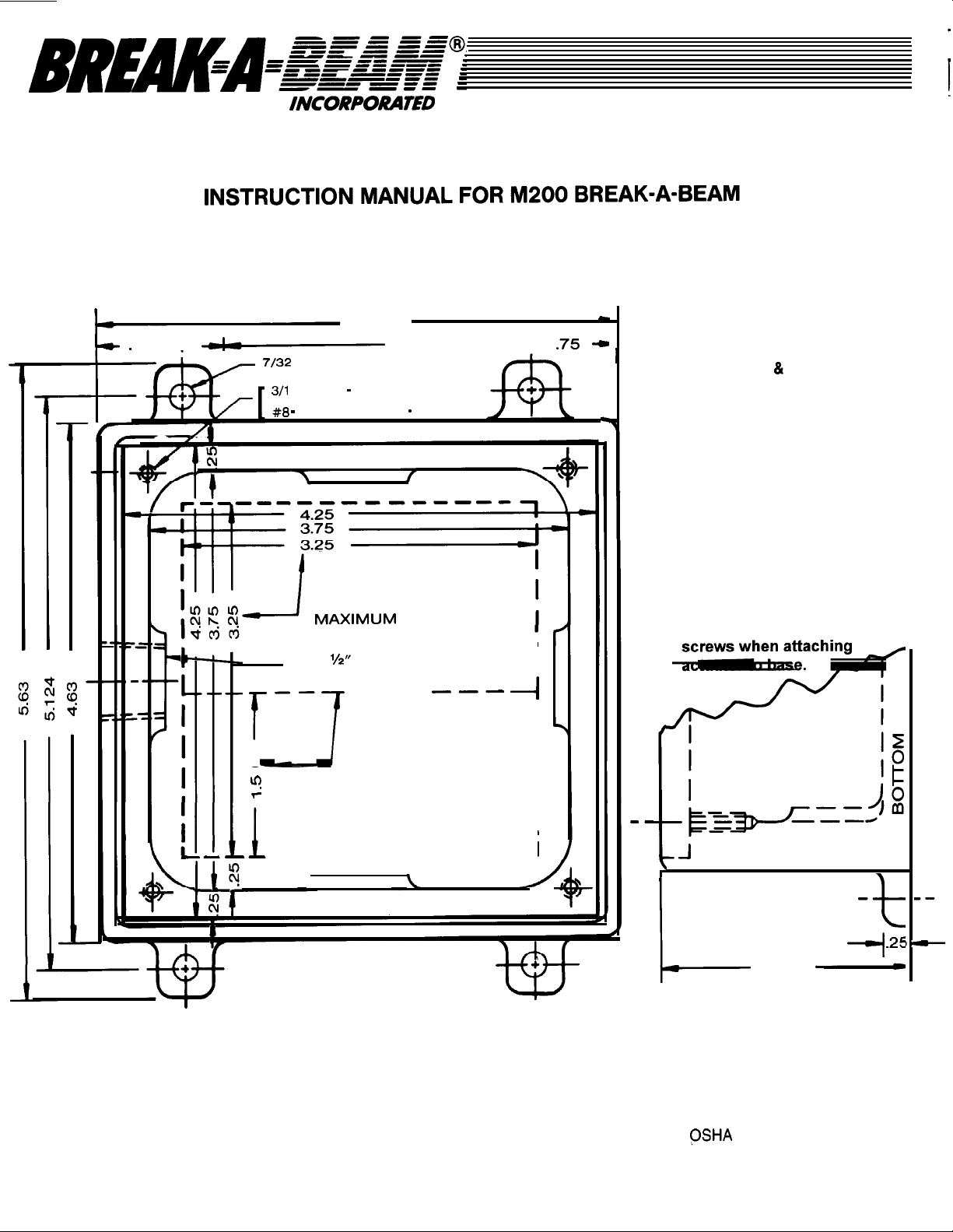
Mounting Specifications
For Actuator and Base
4.63
3.13 --
DIA. x 4
DIA. x 4
32 TAP x SO DEEP
ACTUATOR
BASE
Black lines indicate
Dimensions
for mounting M2 BASE.
Red lines indicate dimensions
&template for mounting the
M200 Actuator to customer
supplied Enclosure.
Location of minimum cut
out can be rotated in
90” increments to
satisfy your mounting
requirements.
Template
CAUTION:
Do not overtighten
0
OPENING
THREADED
CONDUIT OPENING
--
---
MINIMUM
OPENING
I
I
I
I
I
I
------I---
.
J
READ INSTRUCTION MANUAL BEFORE INSTALLING. CUSTOMER IS SOLELY RESPONSIBLE FOR
INSTALLATION.
d
SIDE VIEW
M2 BASE
2.00
OF
BREAK-A-BEAM@ SHOULD ONLY BE USED WHERE POINT OF OPERATION GUARDING DEVICES HAVE
BEEN PROPERLY INSTALLED AND MAINTAINED SO THAT ALL APPROPRIATE
REGULATIONS AND STANDARDS ARE MET MISAPPLICATION OF THESE PRODUCTS ON MACHINERY
LACKING EFFECTIVE POINT OF OPERATION SAFEGUARDS CAN CAUSE SERIOUS INJURY TO THE
OPERATOR.
AND ANSI B 11.1
 Loading...