

Breaching Technologies Hydraulic Breaching Door User Manual
BTI Hydraulic Tool Breaching Door Manual
Model Type: 09
BTI Part Number:
Door: HD / Stand: HDS
Revised: 01 January 2011

Breaching Door Installation
The installation of the BTI training door is straightforward and most likely selfexplanatory by visual examination.
Caution: Through our physical testing of actual doors during the development of
this product, forces in excess of 3000 lbs. have been seen during a breach. Therefore
it is advisable to anchor or mount your product accordingly. Typical house
construction methods are not adequate for the numerous breaches for which this
product has been designed. If you are unsure of your mounting methods, please
consult a professional about these loads.
Hydraulic Door Stand. The Optional BTI Hydraulic Door Stand may be installed to
allow the door to be utilized in a multitude of locations and scenarios. The stand includes
the base plate, door braces and the necessary assembly hardware. The accompanying
diagram shows the assembly.
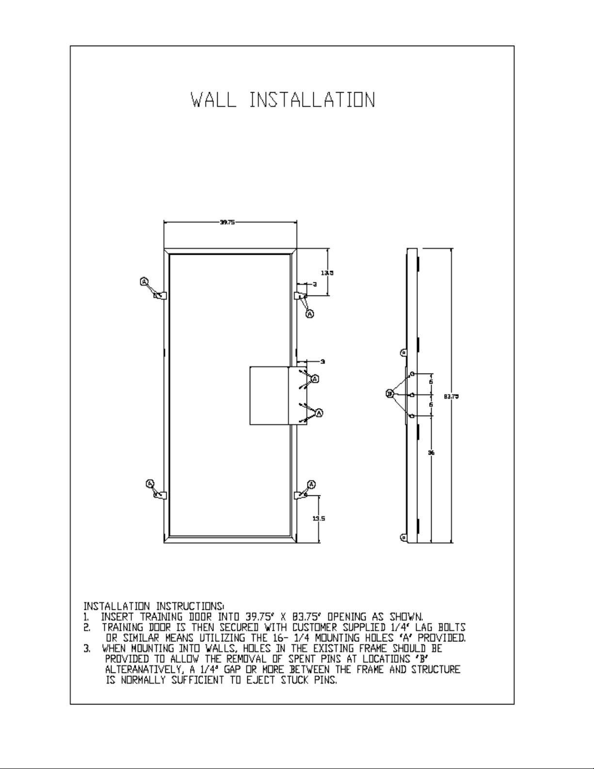
Wall Installation. Installation of the BTI training door into an existing or new frame
type structure is shown in the accompanying diagram. Provisions for mounting the
training door in a “pre-hung” fashion have been provided in the four metal mounting ears
and the frame guard as shown.
Alternate means of mounting such as face mounting or welding are up to the purchaser.
However, BTI Inc. cannot warrantee products, which are mounted in ways that weaken
the frame or structure, or are inconsistent with our design and testing.
Note: When installing the door into the opening of a structure, it is advised that a
provision be made to allow the ejection of stuck spent pins by poking from the backside
of the doorjamb.
One method of accomplishing this is to place 3 aligned holes into the structure
corresponding to the socket holes.
Another method is to shim the door in the opening and allow ½ to 1 inch of clearance in
the area of the sockets. This will allow enough access to the backside to eject the stuck
pins.
Although spent pins that occasionally stick into the socket after
breaching may be removed by pulling with a hook-type tool, it
is consistently easier to poke them out rather than pull them
out.
 Loading...