

Page 1
INSTALLATION INSTRUCTIONS
For LED Pendant
READ AND SAVE THESE INSTRUCTIONS
WARNING! SHUT POWER OFF AT FUSE OR CIRCUIT BREAKER
AVERTISSEMENT!COUPER LE COURANT AU NIVEAU DES FUSIBLES OU DO DISJONCTEU
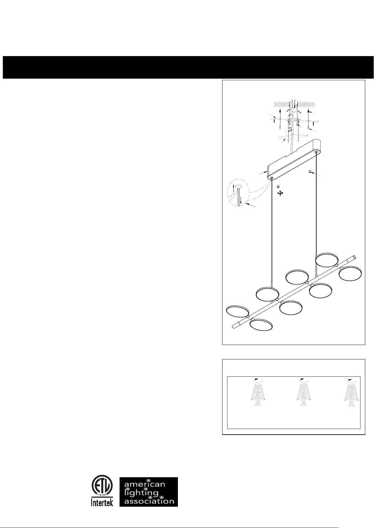
AS SEMBLING THE FIXTU RE (Fig.1)
1 Shut off power at the fuse box or circuit breaker. Remove the
old fixture including the mounting hardware.
2Carefully remove the fixture from the carton and check
that all parts areincluded as show in Figure 1. Unscrew
(G) to remove the mounting plate (A) from the canopy (F),
unscrew hex nut to take the square plate off.
3 Position mounting plate(A) on the ceiling ,and mark the
location of the dry wall anchors(W).Pre-drill the holes for
the dry wall anchors ,Insert the dry wall anchors(W) into
the ceiling ,Attach the mounting plate (A) to the junction
box using the mounting screws(B,size 8#-32N 1/2'’).The
side of the mounting plate marked “GND” must face out.
Place the wood screw (T) through the slot hole into the
dry wall anchor(W) to secure the mounting plate(A) as
shown in Fig. 1.
CONNECTING THE WIRES (Fig. 2)
4 Pass the black/white and bare copper wires from the
hole of the square plate (V), and let the square plate rest
on the canopy (F).Connect the electrical wire as shown
in figure 2,making sure that all wire connectors are
secured. If your junction box has a ground wire
(green or bare copper),connect the ground wire from the
fixture to it. Otherwise connect fixture ground wire (C)
directly to the mounting plate using the green screw (D)
provided. Tuck the wire connections neatly into the
ceiling junction box as you hold the canopy towards the
ceiling.
Fig.1
A
C
D
V
F
S
W
B
T
G
FINISHING THE INSTALLATION (Fig.1)
5 Rise the square plate (V) to the studs to fix with the hex
nuts. )Fix the canopy(F) into the mounting plate (A with
finial(G).Adjust the ength of the cable to pull or push l until the
desired length by pushing down the spring nut (S).
Your installation is now complete. Return power to the junction
box and test the fixture.
CAUTION/ATTENTION: When handling the fixture,do not
apply pressure to the LEDs. Hold the fixture by the frame only.
IMPORTANT: Fixture should be installed by a qualified
electrician to ensure proper wiring and installation.
Dimmable with ELV and/or LED compatible wall
dimmer switches.
C
Page 1/2
US
Fig.2
FIX TURE
WIR ES
BLA CKOR
SMO OTH
HOU SE
WIR ES
BLA CK
(HO T)
FIX TURE
WIR ES
WHI TEOR
RIB BED
HOU SE
WIR ES
WHI TE
(NE UTR AL)
FIX TURE
WIR ES
GRE ENOR
BAR E
COP PER
(GR OUN D)
HOU SE
WIR ES
GRE ENOR
BAR ECOPPE R
(GR OUN D)
Page 2
INSTALLATION INSTRCTIONS
READ AND SAVE THESE INSTRUCTIONS
WARNING! SHUT POWER OFF AT FUSE OR CIRCUIT BREAKER
AVERTISSEMENT!COUPER LE COURANT AU NIVEAU DES FUSIBLES OU DO DISJONCTEU
For LED Pendant
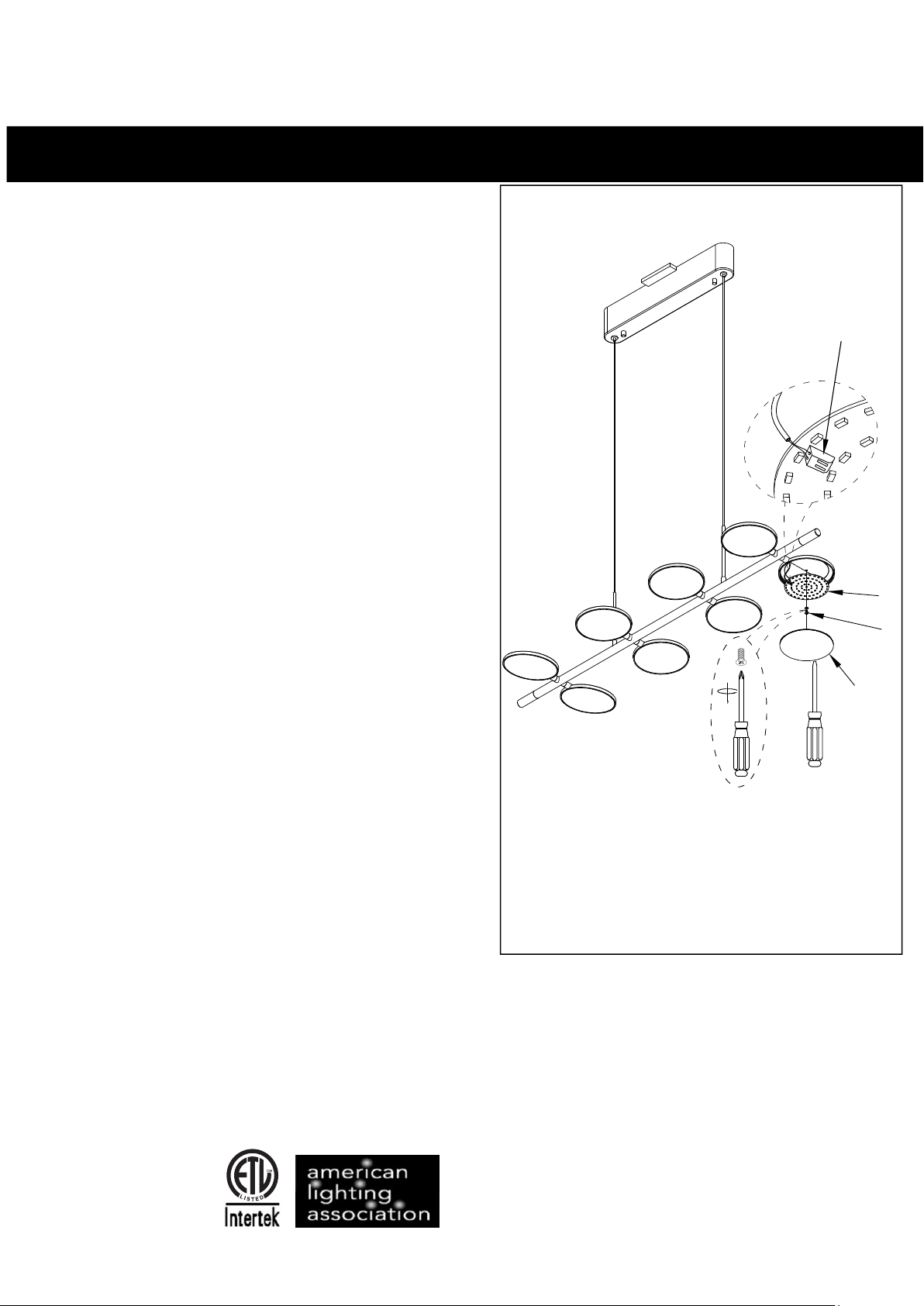
LED module replace(Fig.3)
Shut
1:There have 8 LED modules in each head with this
fixture ,if one of them do not work ,replace it as
shown in Fig. 3. Make sure the power is off before
you replace ;
2:Using a flat screw driver gently pry up the acrylic
shade (H),be careful not to damage the shade or
the finish of the metal head .If shade is broken ,
please ask a replacement from Minka;
3:Unscrew the screw (I) with screwdriver to take off
the LED module;
4:Use a pin press the quick connector (K) ,pull out the
wire ,replace a new module.
5:Repeat 4-1 to assembly the fixture.
Your replace is now complete , return power to the
junction box and text the fixture
off power before replacing
Fig.3
K
J
I
H
Page 2/2
C
US
 Loading...