

Page 1
Bray Controls Commercial Division
13788 West Road, Suite 200A
Houston, Texas 77041
[email protected]
Phone: 1-888-412-2729
Fax: 1-888-412-2720
www.braycommercialdivision.com
STM Series - Flanged Characterized Ball Valves — Installation Instructions
Applications
The STM Series Flanged Ball Valves are designed to
regulate hot and chilled water, 50/50 glycol solutions,
and 25 psig steam in Heating, Ventilating, and Air
Conditioning (HVAC) systems.
IMPORTANT: The STM Series Flanged Ball Valves are intended
to control saturated steam, hot water, and chilled water flow
under normal equipment operating conditions. Where failure or
malfunction of the valve could lead to personal injury or pro
perty damage to the controlled equipment or other property,
additional precautions must be designed into the system. Incorporate and maintain other devices, such as supervisory or
alarm systems or safety or limit controls, intended to warn of or
protect against failure or malfunction of the valve.
Installation
Install the STM Series Flanged Ball Valves with the actuator at or above the centerline of the horizontal piping, as
shown in Figure 1.
IMPORTANT: In steam applications, install the valve with the
stem horizontal to the piping. Failure to follow these guidelines
may shorten the life of the actuator.
01/30/19
When mounting the actuator in the field and before
installing the actuator, use an adjustable wrench to manually rotate the valve stem several times. This rotation
breaks the torque that may have built up during longterm storage.
IMPORTANT: Do not attempt to manually rotate the drive
shaft while the actuator is installed without first releasing the
actuator gears. Manually rotating the drive shaft without
releasing the actuator gears may result in permanent damage
to the actuator.
IMPORTANT: Take care to prevent foreign material such as weld
slag, thread burrs, metal chips, and scale from entering the
piping system. This debris can damage or severely impede the
operation of the valve by embedding itself in the seats, scoring the valve, and ultimately resulting in seat leakage. If the
debris becomes embedded in the seats, subsequent flushing and
filtering of the piping system with the valve installed does not
remedy the problem.
To minimize heat transfer in steam applications, wrap the
valve and piping with insulation.
Allow at least 4 in. (102 mm) of clearance from the top of
the shaft to remove the actuator (as noted in dimensions).
Figure 1: Recommended Mounting Positions for Non-Steam Applications
A AB
B
A
A
B
A
A
B
A
A
A
A
B
A
A
B
A
A
B
A
A
B
1
Page 2
STM Series - Flanged Characterized Ball Valves — Installation Instructions Continued
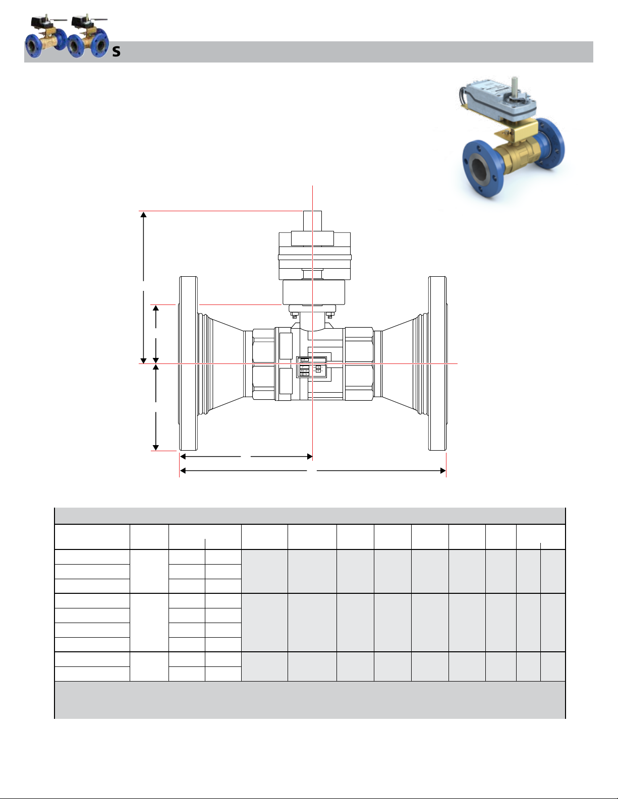
STM - 2-Way Dimensions
D
E
A
B
2-Way STM Dimensions
Flow Coefficient
Valve Models
STM 250-2-47
STM 250-2-74
STM 250-2-117
STM 3-2-74
STM 3-2-117
STM 3-2-176
STM 3-2-211
STM 4-2-117
STM 4-2-176
- Allow a minimum of 4 inches for actuator removal.
- Weights are for valve bodies only.
- Dimensions may vary depending on the actuator
- Dimensions Shown are based on largest actuator available for this series.
Size
in.(mm)
2 1/2
(65)
3
(80)
4
(100)
Cv Kv
47
74
117
74
117
176
211
117
176
101.2
101.2
152.2
182.5
101.2
152.2
40.7
64.0
64.0
Bolt Hole
Diameter
5.50
(139)
6.00
(152)
7.50
(191)
C
Number of
Bolt Holes
4
4
8
A B C D E Weight
3.50
(89)
3.75
(95)
4.50
(114)
5.71
(145)
6.10
(155)
6.89
(175)
11.42
(290)
12.20
(310)
13.77
(350)
10.25
(260)
10.25
(260)
10.25
(260)
2.05
(52.1)
2.49
(63.2)
3.09
(75.5)
lbs. kg.
34
36
44
15
16
20
2
Page 3
STM Series - Flanged Characterized Ball Valves — Installation Instructions Continued
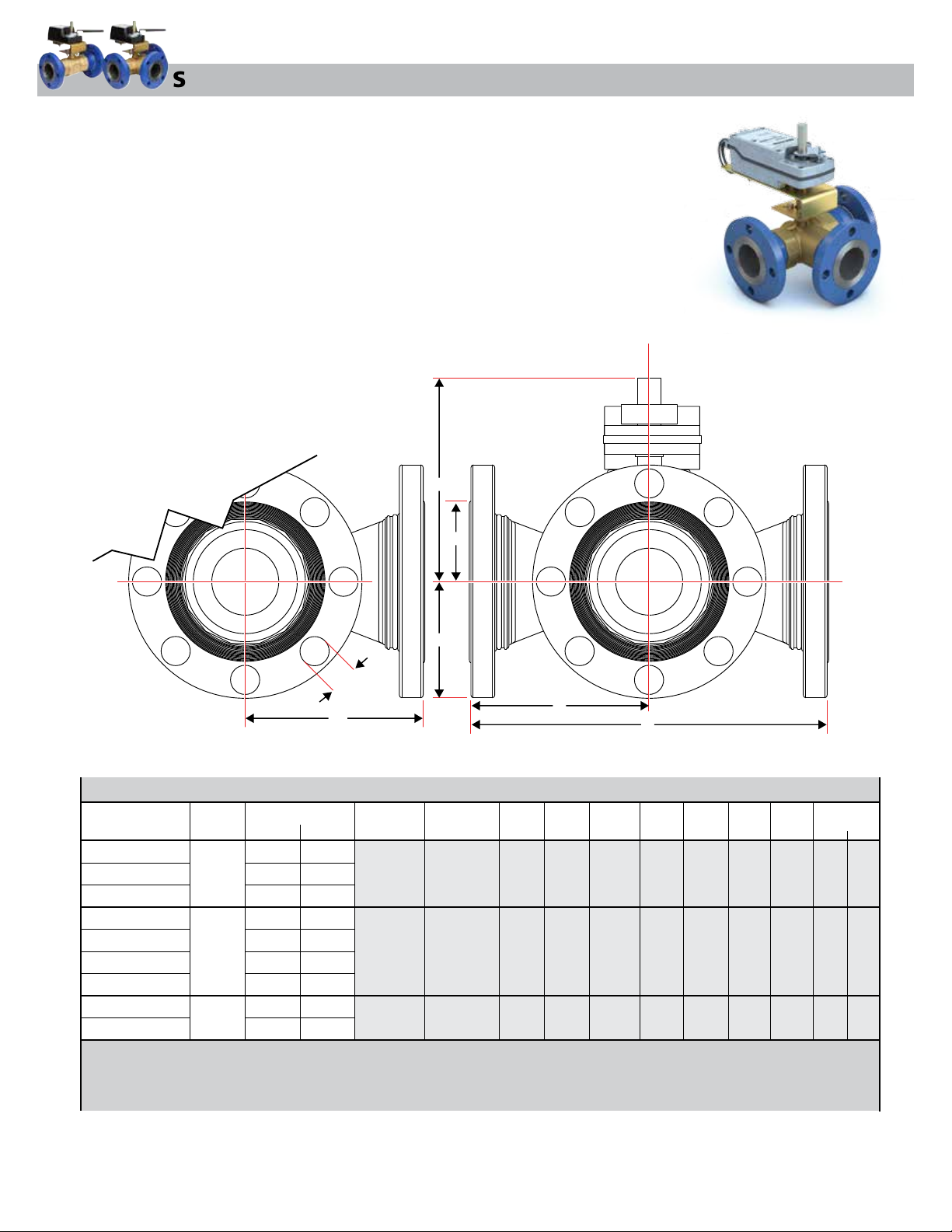
STM - 3-Way Dimensions
D
F
G
3-Way STM Dimensions
Size
Valve Models
in.(mm)
STM 250-3-47
STM 250-3-74
2 1/2
STM 250-3-117
STM 3-3-74
STM 3-3-117
STM 3-3-176
STM 3-3-211
STM 4-3-117
STM 4-3-176
- Allow a minimum of 4 inches for actuator removal.
- Weights are for valve bodies only.
- Dimensions may vary depending on the actuator
- Dimensions Shown are based on largest actuator available for this series.
- Bypass Cv/Kv is 50% of the nominal service Cv.
(100)
Flow Coefficient
(65)
3
(80)
4
Cv Kv
47
74
117
74
117
176
211
117
176
101.2
101.2
152.2
182.5
101.2
152.2
40.7
64.0
64.0
Bolt Hole
Diameter
5.50
(139)
6.00
(152)
7.50
(191)
E
A
Number of
Bolt Holes
4
4
8
B
C
A B C D E F
3.50
5.71
11.42
(89)
3.75
(95)
4.50
(114)
(145)
6.10
(155)
6.89
(175)
(290)
12.20
(310)
13.77
(350)
10.25
(260)
10.25
(260)
10.25
(260)
2.05
(52.1)
2.49
(63.2)
3.09
(75.5)
0.75
(19.1)
0.75
(19.1)
0.75
(19.1)
G Weight
lbs. kg.
5.87
6.26
7.05
43
49
62
(149)
(159)
(179)
20
22
28
3
Page 4
STM Series - Flanged Characterized Ball Valves — Installation Instructions Continued
STM - Mounting
Location Considerations
IMPORTANT: Protect the actuator from dripping
water, condensation, and other moisture. Water or
moisture could result in an electrical short, which
may damage or affect the operation of the actuator.
IMPORTANT: Do not cover the actuator with
thermal insulating material. High ambient
temperatures may damage the actuator, and a hot
water pipe, a steam pipe, or other heat source may
overheat it.
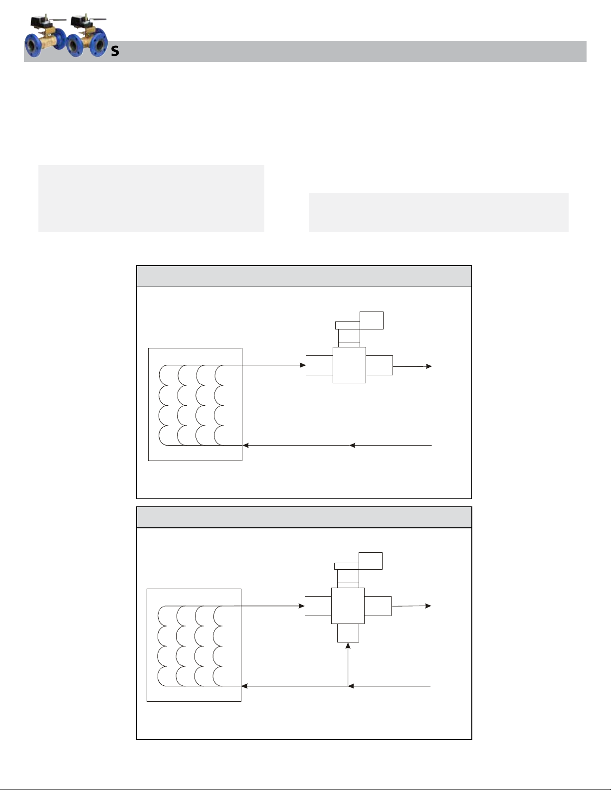
STM - Piping Diagrams
COIL
Piping
Be sure to wire the input lines to the electric actuator
correctly for the valve to move in the proper direction.
See piping diagrams below for typical two and threeway piping configurations.
Note: Mount the valve downstream from the coil to
minimize heat transfer to the actuator.
IMPORTANT: Use copper conductors only. Make all wiring
connections in accordance with local, national, and regional
regulations. Do not exceed the actuator’s electrical ratings.
2-Way
PORT
A
PORT
B
RETURN
COIL
3-Way
PORT
SUPPLY
A
PORT
AB
PORT
B
RETURN
SUPPLY
4
Page 5
STM Series - Flanged Characterized Ball Valves — Installation Instructions Continued
STM - Setup and Adjustments
Port A has the flow characterizing disk. Connect Port A
to the outlet from the coil. On three-way models, use
Port B as the bypass port.
Two-way STM Series Ball Valves are fully open
when the electric actuator is fully Counterclockwise
(CCW) and fully closed when the electric actuator is
fully Clockwise (CW).
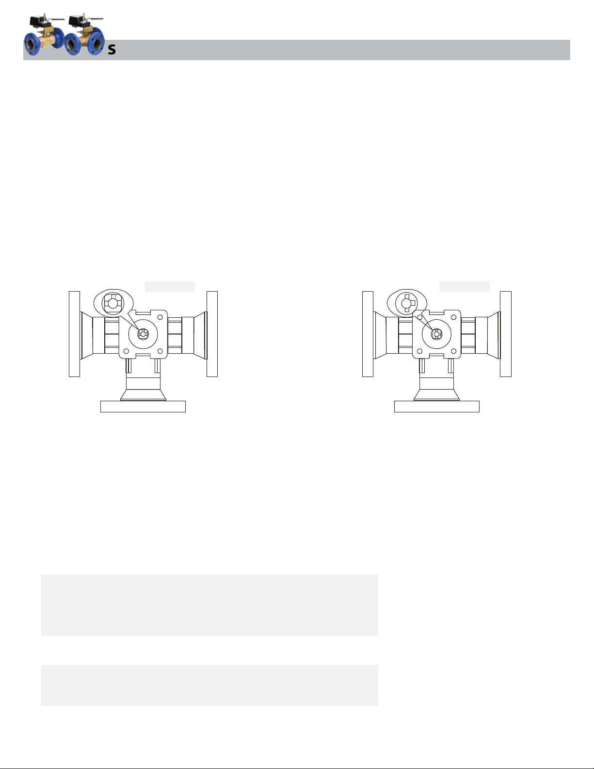
For three-way valves, the Coil Port A and Common
Port AB are fully open when the electric actuator is
fully CCW, as shown in Figure 1. The Bypass Port B and
Common Port AB are fully open when the actuator is
fully CW, as shown in Figure 2.
FIGURE 1 FIGURE 2
Port A
Coil
Port AB
Common
For non-spring return and spring-to-open proportional
control models in the Direct Acting (DA) mode, a
minimum control signal drives the electric actuator to
the fully CCW position while a maximum control signal
drives the electric actuator in the fully CW position.
For spring-to-close proportional control models in the
DA mode, a minimum control signal drives the electric
actuator to the fully CW position, while a maximum
control signal drives the electric actuator to the fully
CCW position.
Port A
Coil
Port AB
Common
Port B — Bypass
Figure 1: STM Series Three-Way Ball Valve
(Coil Port A Open to Common Port AB)
Figure 2: STM Series Three-Way Ball Valve
(Bypass Port B Open to Common Port AB)
STM - Troubleshooting
Servicing the Actuator or Piping System
When servicing the electric actuator or the piping system:
• Disconnect the power supply to the actuator.
WARNING: Risk of Electric Shock. Disconnect each of multiple power
supplies before making electrical connections. More than one disconnect
may be required to completely de-energize equipment. Contact with
components carrying hazardous voltage can cause electric shock and may result
in severe personal injury or death.
• Relieve the pressure in the piping system
CAUTION: Risk of Property Damage. Do not apply power to the system before
checking all wiring connections. Short circuited or improperly connected wires
may result in permanent damage to the equipment.
Port B — Bypass
5
 Loading...