

Page 1

A Subsidiary of BRAY INTERNATIONAL, Inc.
TRIAD SERIES BALL VALVES
(FP2000/FP3000 SP2000/SP3000)
INSTALLATION - MAINTENANCE MANUAL
Installation and Maintenance Manual
®
Triad Series Ball Valves
Date: August 2011 / Page 1 of 7
DESIGN
The design features of this valve include a three piece
construction, allowing ease of maintenance without
special tools. These valves feature a “free floating”
ball. The ball is not fixed, but is free to move with the
line pressure. As a result of this feature, these valves
are capable of tight shut-off with flow in either direction
regardless of the position of the valve in the line.
The downstream seat, opposite the pressurized side of
a closed valve, must carry the load exerted by the line
pressure on the ball, while the upstream seat is subject
to little load or wear. Turning the valve end-for-end in
the pipeline will increase useful seat life by dividing seat
wear between the two seats.
1. USE:
The valve should be maintained as part of a preventative
maintenance program and in accordance with Flow-Tek’s
recommended pressure, temperature and corrosion limits
to ensure a long service life. During shipment, storage,
and in operation, the valve should be fully open or fully
closed (“open” is preferred for shipping and storage).
Do not use in throttling service without investigating flow
and pressure conditions.
WARNING: Before installing this equipment, confirm that
it is suitable for the intended service. The identifications
tags describe the maximum allowable service conditions
for this product. Be sure that the installation is protected
by appropriate pressure control and safety devices to
ensure that acceptable limits are not exceeded.
2. OPERATION:
Operation of the valve is done by turning the handle a
1/4 turn (90 degree turn). CW to close, CCW to open.
A. VALVE OPEN POSITION
Valves with actuators should be checked for actuator -valve
alignment. Misalignment will result in high operational
torque and damage to valve stem and seals.
3. STEM SEAL ADJUSTMENT:
For 1/2”- 2”, if slight leakage is noted at stem, straighten
lock washer tab, tighten stem nut to flatten Bellville Washers, back stem nut off 1/4 turn, secure lock washer tab.
For sizes larger than 2”, simply tighten gland bolts evenly
until leak stops. Do not over tighten.
4. GENERAL INFORMATION FOR ON-SITE
INSTALLATION:
The valve may be fitted in any position on the pipeline.
Before installing the valves, the pipes must be flushed
clean of dirt, burrs, and welding residues, or the seats
and ball surface will be damaged.
5. DISASSEMBLY & CLEANING PROCEDURES:
CAUTION: Line must be depressurized before disassembly.
Valve should be cycled to assure there is no pressure is
trapped in valve cavity. Ball valves can trap pressurized
media when closed. Flush line with valve 1/2 open to
remove hazardous media.
WARNING: DO NOT remove packing gland or any other
valve parts while line is under pressure!
Stem seal leakage may be corrected without disassembly
by tightening the packing gland nut until such leakage
stops. If the leakage continues or valve operating torque
becomes excessive, the seals are worn and replacement
will be necessary.
If the valve has been used to control hazardous media,
it must be decontaminated before disassembly.
The handle is parallel with the pipeline.
B. VALVE IN CLOSED POSITION
The handle is perpendicular to the pipeline.
FLOW-TEK, Inc. Tel: 832.912.2300
8323 N. Eldridge Pkwy #100 Fax: 832.912.2301
Houston, Texas 77041 www.flow-tek.com
It is recommended that the following steps be taken for
safe removal and assembly.
As shipped from the factory, Valves contain Silicone based
lubricant. This is for break-in and may be removed by
© 2011 Flow-Tek, Inc.
Page 2

A Subsidiary of BRAY INTERNATIONAL, Inc.
Installation and Maintenance Manual
®
Triad Series Ball Valves
Date: August 2011 / Page 2 of 7
disassembly and solvent washing, if it is objectionable
for a particular application.
6. DISASSEMBLY FOR STEM AND SEAL REMOVAL:
1. Remove flange connections and lift valve from line
for servicing.
NOTE: Care should be taken to avoid scratching or
damaging mating faces. The valve should be adequately supported and in the open position before
beginning.
2. Loosen handle set screw and remove handle and
stop plate. Next, remove gland nuts, gland flange
and gland.
3. Remove body end cap screws, using proper wrench
size. Lift off body end. One seat should come out
with body end.
4. Repeat the removal procedure for the other flange
end. Take out other seat.
5. To remove the ball, rotate the stem so ball is fully
closed. Lift the ball from body, using a strap and lift
device if necessary. NOTE: Extreme caution should
be taken to avoid damage to the ball.
6. The stem must be removed from inside the body - a
tap on the top of the stem should loosen it. The thrust
washer should come out with the stem. Then remove
the stem packing.
7. VISUAL INSPECTION:
Clean and inspect metal parts. It is not necessary to replace
the ball and stem unless the seating surfaces have been
damaged by abrasion or corrosion. Replacement of all
soft parts is strongly recommend whenever the valve is
disassembled for reconditioning. This is the surest protection against subsequent leakage after valve assembly.
The replacement parts can he ordered in kit form.
NOTE: The valve may be assembled and operated dry
where no lubricants are allowed in the system; however,
a light lubrication of mating parts will aid in assembly
and reduce initial operating torque. Lubricant used must
be compatible with the intended line fluid.
ASSEMBLY:
½”-2” VALVE ASSEMBLY PROCEDURES:
Hold the body in a vise firmly enough so it will not move
but do not crush it.
Put washer protector (11B) and thrust washer (12) on
valve stem (5) and slide the stem into the stem hole in
valve body (1);
Slide the stem packing components (14) onto the stem
until it is sealed against the bottom of the stem hole;
Put packing protector (11A). then packing gland sleeve
(15) onto the stem, and top of the stem packing;
Turn the stem until the stem flat is parallel to the port
centerline (so that the ball can fit onto the stem):
lnstall one seat (4) and two body seals inside an end
cap (2), make sure the spherical curvature side of the
seat will face the ball;
Install the end cap (2) with cap screws (9) and tighten
screws to the values indicated in Table 1.
Rotate the stem to the closed position and install the ball
(3) inside the valve body. The stem flats will fit into the
slot on top of the ball;
Turn the stem so that the ball is in the open position (the
ball will not fall out of the valve);
lnstall the second seat (4) and two body seals inside the
remaining end cap (2), make sure the spherical curvature
side of the seat will face the ball;
Install the end cap (2) with cap screws (9) and tighten
screws to the values indicated in Table 1.
Put Belleville washer (13) together in series mode (bottom Belleville washer curve facing up, the top Belleville
washer curve facing down). and then place them onto
the stem, on top of the packing gland sleeve;
Put tab washer (19) on top of the Belleville washer and
tighten the stem gland nut (26) onto the stem to the required stem gland nut torque value as specified in the
chart. (Note: The use of a bore alignment tool, about
1.0 mm I0.04 inch) less than the internal diameter of
FLOW-TEK, Inc. Tel: 832.912.2300
8323 N. Eldridge Pkwy #100 Fax: 832.912.2301
Houston, Texas 77041 www.flow-tek.com
© 2011 Flow-Tek, Inc.
Page 3

A Subsidiary of BRAY INTERNATIONAL, Inc.
Installation and Maintenance Manual
®
Triad Series Ball Valves
Date: August 2011 / Page 3 of 7
the end cap and ball, inserted through the end cap and
ball will prevent the ball from turning as the stem gland
nut is lightened on the stem.
Material for the bore alignment tool should be made
from a material softer than 300 Series S.S. so that it
will not inadvertently scratch the valve end cap or ball.
Suggested materials: aluminum T6061. Acetal or other
suitable hard polymer/plastic material.)
Secure the tab washer with one ear bending up; Place
the handle (25) onto the stem, on top of the stem gland
nut (26A);
Secure the handle (25) with the stem lock nut (26).
3”-4”” VALVE ASSEMBLY PROCEDURES:
Put washer protector (11B), thrust washer (12) and stem
bearing (13) on valve stem (5) and slide the stem Into
the stem hole on valve body (1):
Slide the stem packing (14) onto the stem until it is seated
against the upper bottom of the stem hole;
Put packing protector (IlA), then packing gland sleeve
(15) onto the stem, on top of the stem packing;
Install packing gland (16) on top of the packing gland
sleeve, lightly tighten to secure packing gland with packing gland bolt (17).
Install stop housing (20), secure stop housing with housing bolts (21) hand tight. Install travel stop (22) and
snap ring (30):
lnstall one seat (4 ) and two body seals inside an end
cap (2), make sure the spherical curvature side of the
seat will face the ball;
Install the end cap (2) with cap screws (9) and tighten
screws to the values indicated in Table 1.
Turn the stem to the closed position (wrench flats on stem
perpendicular to pipeline);
Install the ball (3) inside the valve body. The stem flats
will fit into the slot on top of the ball;
Turn the stem so that the ball is in the open position (the
ball will not fall out of the valve);
Install the second seat (4) and two body seals inside the
remaining end cap (2), make sure the spherical curvature
side of the seat will face the ball;
Install the end cap (2) with cap screws (9) and tighten
screws to the values indicated in Table 1.
Cycle the valve slowly several times. By cycling slowly,
the seats will conform to the ball. A fast turning motion
initially may damage the seats before they have a chance
to form the proper seal:
Tighten the packing gland bolts (17) gradually until there
is no leakage through the packing. Over-tightening can
result in excess torque and accelerated wear.
Install handle (25) on to the valve stem and secure the
handle with handle bolt (27).
Table 1
Tightening torques for end cap screws
Valve Size
Bolt Torque (lb-in)
FLOW-TEK, Inc. Tel: 832.912.2300
8323 N. Eldridge Pkwy #100 Fax: 832.912.2301
Houston, Texas 77041 www.flow-tek.com
1/2” 3/4” 1” 1-1/4” 1-1/2” 2” 3” 4”
140 210 210 550 550 550 996 996
© 2011 Flow-Tek, Inc.
Page 4

A Subsidiary of BRAY INTERNATIONAL, Inc.
Item Name
1 Body
2 End Cap
3 Ball
4 Seat
5 Stem
6A Body Seal
6B Body Seal
9 Body Bolt*
10 Anti-Static Device
11A Packing Protector
11B Thrust Washer Protector
12 Thrust Washer
14 Stem Packing
15 Packing Gland Sleeve
18 Belleville Washer
19 Tab Lock Washer
23 Travel Stop Set Sleeve
24 Travel Stop Bolt
25 Handle
26 Lock Nut
28 Handle Sleeve
29 Locking Device
*Items contained in repair kit
•
®
12
11B
10
Installation and Maintenance Manual
Triad Series Ball Valves
Date: August 2011 / Page 4 of 7
Valve Sizes:
1/4” through 2 1/2”
28
26
25
29
26
24
23
19
18
15
11A
14
5
6B
9
2
6A
4
6A
6B
2
9
FLOW-TEK, Inc. Tel: 832.912.2300
8323 N. Eldridge Pkwy #100 Fax: 832.912.2301
Houston, Texas 77041 www.flow-tek.com
1
3
4
Flow-Tek offers the seat, body
seals, thrust washer and stem
packing as recommended
spare parts. These parts are
available as a packaged
repair kit.
© 2011 Flow-Tek, Inc.
Page 5
A Subsidiary of BRAY INTERNATIONAL, Inc.
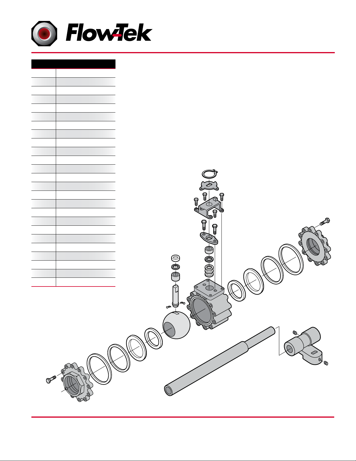
14
11
15
16
17
10
5
20
21
22
30
11AB
12
13
3
4
7
6
A
6
B
1
2
25A
25 B
27
4
7
6
A
6
B
2
9
9
Item Name
1 Body
2 End Cap
3 Ball
4 Seat
5 Stem
6A Body Seal
6B Body Seal
7 Seat Support
9 Body Bolt*
10 Anti-Static Device
11A Packing Protector
11B Thrust Washer Protector
12 Thrust Washer
13 Stem Bearing
14 Stem Packing
15 Packing Gland
16 Packing Follower
17 Gland Bolt
20 Stop Housing
21 Housing Bolt
22 Travel Stop
25A Handle
25B Handle Junction
27 Handle Bolt
30 Snap Ring
*Items contained in repair kit
®
Valve Sizes:
3” and 4”
Installation and Maintenance Manual
Triad Series Ball Valves
Date: August 2011 / Page 5 of 7
FLOW-TEK, Inc. Tel: 832.912.2300
8323 N. Eldridge Pkwy #100 Fax: 832.912.2301
Houston, Texas 77041 www.flow-tek.com
© 2011 Flow-Tek, Inc.
Page 6

A Subsidiary of BRAY INTERNATIONAL, Inc.
Installation and Maintenance Manual
®
Triad Series Ball Valves
Date: August 2011 / Page 6 of 7
9. INSTALLATION OF THREADED VALVES
Valve can be screwed on without the use of union or
with the end caps removed from the body.
The use of a thread sealant is recommended;
Apply wrench only on the valve end being tightened.
Do not tighten by applying torque to the opposite end
cap or other valve component. Tightening by using the
valve body, handle or the opposite end cap can seriously
damage the valve; Use a wrench on both the second
end cap and pipe to avoid applying torque to the body
through the bolting.
In some applications, screwed valves may be back-welded. Disassemble as per instructions for weld end valves.
Confirm that the end cap bolt holes are aligned with the
body screw holes on both ends and that the end caps
are parallel and correctly spaced to fit the valve body
before re-assembly or back welding.
Do not use the body screws to pull the pipe ends together
or into alignment.
10. INSTALLATION OF EXTENDED WELD END
VALVE
Insure that appropriate weld procedures are implemented
that are compatible with the materials used.
Butt weld valves with 3 inch or longer extended weld
ends do not require disassembly for installation welding.
Simply ensure that ball is in the full open position, and
perform normal welding procedures, using care that the
valve body does not reach a temperature above 200F.
11. INSTALLATION OF WELD-END VALVES
(FPISP2000, FPISP3000 Series)
Insure that appropriate weld procedures are implemented
that are compatible with the materials used.
Tack weld the valve to the pipe at four points on both
end caps.
With the valve in open position, (the valve is in the open
position when the handle is parallel to the axis of the
valve and pipe), loosen all body bolts, take the body out.
Turn the handle in the half open position to assist in the
removal of the seats and body gaskets.
Turn handle in closed position and remove ball.
Place all removed parts in a clean and secure place.
Replace the body and all bolts and tighten them slightly.
This operation is very important, so that the body and
end caps remain perfectly parallel, thus preventing any
leakage at the body joint after welding.
Finish welding both end caps onto the pipe.
When cool, clean end caps, turn valve to closed position and replace ball. Turn valve in open position and
replace seats and body gaskets.
Place body between the two end connections; then
replace all bolts and tighten firmly
(See table 1. Tightening torques for end cap screws).
FLOW-TEK, Inc. Tel: 832.912.2300
8323 N. Eldridge Pkwy #100 Fax: 832.912.2301
Houston, Texas 77041 www.flow-tek.com
© 2011 Flow-Tek, Inc.
Page 7

A Subsidiary of BRAY INTERNATIONAL, Inc.
Installation and Maintenance Manual
®
Triad Series Ball Valves
Date: August 2011 / Page 7 of 7
12. Short and Long Term Storage
Short term:
1. Short term storage is defined as storage of products and equipment to be used in the construction
of a project for periods of one to three months.
2. Ball valves should remain in the original shipping
containers be placed on pallets of wood or other
suitable materials. End protectors should remain
on the valve ends to prevent the entrance of dirt.
3. Valves should be stored in the open position to
protect the ball and seats.
4. Storage of ball valves can be in an open uncovered area provided provisions are made
for inclement weather such as tarps or sheeting.
Valves with electric actuators shall be stored under
cover until ready for installation.
Long term:
1. Long term storage is storage of products and/or
equipment for periods of three months or more.
fications tags describe the maximum allowable
service conditions for this product.
4. Be sure that the installation is protected by appropriate pressure control and safety devices to
ensure that acceptable limits are not exceeded.
5. Confirm that line pressure has been removed
and that there is no pressure trapped within the
valve prior to beginning service. Do not attempt
to remove any packing components or other fittings before confirming that pressure has been
completely removed!
6. Do not begin service work without proper tools
and protective safety measures.
7. The work area should be clear of obstructions
and other safety hazards.
2. Valves should be stored in the open position to
protect the ball and seats.
3. Ball valves should remain in the original shipping
containers placed on pallets of wood or other
suitable materials and stored indoors. End protectors should remain on the valve ends to prevent
the entrance of dirt. The storage environment
should be dry and not have severe swings in
temperature and humidity.
13. Safety Summary
1. Read completely and understand all instructions provided prior to beginning installation or
maintenance.
2. Follow all instructions as described using the
correct tools for the job.
3. Before installing this equipment, confirm that it
is suitable for the intended service. The identi-
FLOW-TEK, Inc. Tel: 832.912.2300
8323 N. Eldridge Pkwy #100 Fax: 832.912.2301
Houston, Texas 77041 www.flow-tek.com
© 2011 Flow-Tek, Inc.
 Loading...