

Page 1
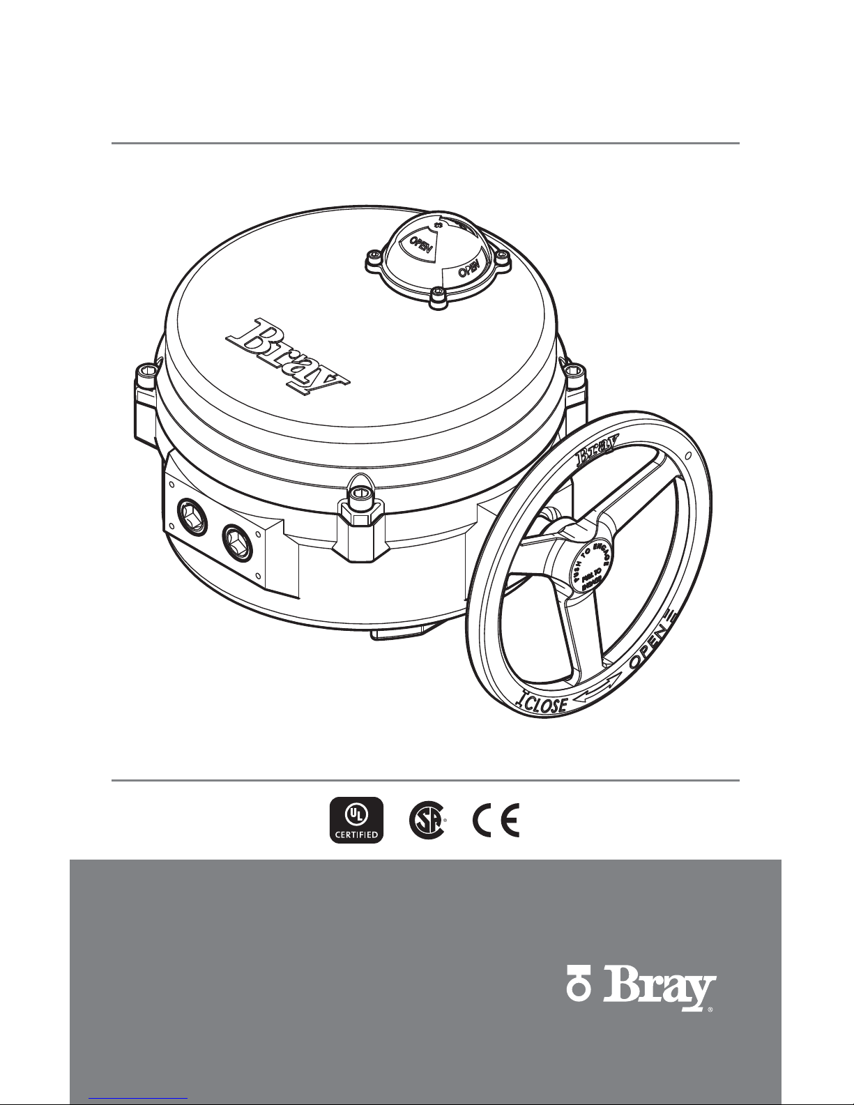
SERIES 70
ELECTRIC ACTUATOR
Installation, Operation and Maintenance Manual
THE HIGH PERFORMANCE COMPANYBRAY.COM
Page 2

Page 3

1
Series 70 Electric Actuator
Installation, Operation and Maintenance Manual
FOR MORE INFORMATION ON THIS PRODUCT AND OTHER BRAY PRODUCTS
PLEASE VISIT OUR WEBSITE – bray.com
Table of Contents
Safety Instructions - Definition of Terms . . . . . . . . . . . . . . . . . . . . . . . . . . . . . . . .2
Hazard-Free Use. . . . . . . . . . . . . . . . . . . . . . . . . . . . . . . . . . . . . . . . . . . .2
Qualified Personnel . . . . . . . . . . . . . . . . . . . . . . . . . . . . . . . . . . . . . . . . . .2
Part Numbering System Reference Chart . . . . . . . . . . . . . . . . . . . . . . . . . . . . . . .3
Introduction. . . . . . . . . . . . . . . . . . . . . . . . . . . . . . . . . . . . . . . . . . . . . .3
Principle of Operation . . . . . . . . . . . . . . . . . . . . . . . . . . . . . . . . . . . . . . .3
Electrical Operation. . . . . . . . . . . . . . . . . . . . . . . . . . . . . . . . . . . . . . . . .3
Mechanical Operation . . . . . . . . . . . . . . . . . . . . . . . . . . . . . . . . . . . . . . .3
Actuation . . . . . . . . . . . . . . . . . . . . . . . . . . . . . . . . . . . . . . . . . . . . . . .4
Manual Operation . . . . . . . . . . . . . . . . . . . . . . . . . . . . . . . . . . . . . . . . .4
Remote Operation . . . . . . . . . . . . . . . . . . . . . . . . . . . . . . . . . . . . . . . . .4
S70 On/Off Actuator with Interposing Relay Board (I.R.B.) . . . . . . . . . . . . . . . . . . . .4
Servo NXT . . . . . . . . . . . . . . . . . . . . . . . . . . . . . . . . . . . . . . . . . . . .5
Storage . . . . . . . . . . . . . . . . . . . . . . . . . . . . . . . . . . . . . . . . . . . . . . .6
Commissioning . . . . . . . . . . . . . . . . . . . . . . . . . . . . . . . . . . . . . . . . . . . .6
Mounting the Actuator. . . . . . . . . . . . . . . . . . . . . . . . . . . . . . . . . . . . . . .6
Wiring the Actuator . . . . . . . . . . . . . . . . . . . . . . . . . . . . . . . . . . . . . . . .7
Setting Travel Limit Switches . . . . . . . . . . . . . . . . . . . . . . . . . . . . . . . . . . . .7
Setting Mechanical Travel Stops . . . . . . . . . . . . . . . . . . . . . . . . . . . . . . . . . .8
Disassembly and Assembly . . . . . . . . . . . . . . . . . . . . . . . . . . . . . . . . . . . . . 10
Field or Factory Installable Options . . . . . . . . . . . . . . . . . . . . . . . . . . . . . . . . . 13
Auxiliary Switches . . . . . . . . . . . . . . . . . . . . . . . . . . . . . . . . . . . . . . . . 13
Heater . . . . . . . . . . . . . . . . . . . . . . . . . . . . . . . . . . . . . . . . . . . . . . 13
Torque Switches . . . . . . . . . . . . . . . . . . . . . . . . . . . . . . . . . . . . . . . . . 14
Local Control Station . . . . . . . . . . . . . . . . . . . . . . . . . . . . . . . . . . . . . . .14
Control Station Kit . . . . . . . . . . . . . . . . . . . . . . . . . . . . . . . . . . . . . . . . 14
Battery Backup Unit . . . . . . . . . . . . . . . . . . . . . . . . . . . . . . . . . . . . . . . 15
Indication of Remote Control. . . . . . . . . . . . . . . . . . . . . . . . . . . . . . . . . . .16
Spinner. . . . . . . . . . . . . . . . . . . . . . . . . . . . . . . . . . . . . . . . . . . . . .16
Receptacles (Quick Connectors) . . . . . . . . . . . . . . . . . . . . . . . . . . . . . . . . . 16
External Signal Feedback Potentiometer . . . . . . . . . . . . . . . . . . . . . . . . . . . . . 17
Appendix A . . . . . . . . . . . . . . . . . . . . . . . . . . . . . . . . . . . . . . . . . . . . . 18
Basic Tools . . . . . . . . . . . . . . . . . . . . . . . . . . . . . . . . . . . . . . . . . . . . 18
Appendix B . . . . . . . . . . . . . . . . . . . . . . . . . . . . . . . . . . . . . . . . . . . . . 19
Actuator Troubleshooting Chart . . . . . . . . . . . . . . . . . . . . . . . . . . . . . . . . . 19
Series 70 – Size 003, 006 – Electric Actuator Exploded View . . . . . . . . . . . . . . . . . . . . 20
Series 70 – Size 008, 012, 020 – Electric Actuator Exploded View . . . . . . . . . . . . . . . . . .22
Series 70 – Size 030, 050, 065 – Electric Actuator Exploded View . . . . . . . . . . . . . . . . . .24
Series 70 – Size 130, 180 – Electric Actuator Exploded View . . . . . . . . . . . . . . . . . . . . 26
Series 70 – Size 130, 180 – 3:1 Gear Box Exploded View . . . . . . . . . . . . . . . . . . . . . . 28
Page 4
2
Series 70 Electric Actuator
Installation, Operation and Maintenance Manual
Hazard-Free Use
This device left the factory in proper condition to be
safely installed and operated in a hazard-free manner.
The notes and warnings in this document must be
observed by the user to ensure hazard-free operation
of this device.
All necessary precautions need to be taken to prevent
damage due to rough handling, impact, or improper
storage. Do not use abrasive compounds to clean the
device, or scrape its surfaces with any objects.
Configuration and setup procedures for this device
are described in this manual. Proper configuration and
setup are required for the safe operation of this device.
The control system in which this device is installed must
have proper safeguards to prevent injury to personnel,
or damage to equipment, should a failure of system
components occur.
The device generates large mechanical force during
normal operation.
Qualified Personnel
The actuator must only be installed, commissioned,
operated and repaired by qualified personnel.
Installation, commissioning, operation and maintenance must be performed under strict observation of
all applicable codes, standards and safety regulations.
As per this document, a qualified person is one who
is trained in:
• The operation and maintenance of electric
equipment and systems in accordance with
established safety practices.
• Procedures to energize, de-energize, ground,
tag and lock electrical circuits and equipment in
accordance with established safety practices.
• The proper use and care of personal protective
equipment (PPE) in accordance with established
safety practices.
• First aid.
• In cases where the device is installed in a potentially
explosive (hazardous) location – is trained in
the operation, commissioning, operation and
maintenance of equipment in hazardous locations.
Reference is specifically made here to observe all
applicable safety regulations for actuators installed in
potentially explosive (hazardous) locations.
Safety Instructions - Definition of Terms
READ AND FOLLOW THESE INSTRUCTIONS
SAVE THESE INSTRUCTIONS
indicates a potentially hazardous situation which, if not avoided, could
result in death or serious injury.
indicates a potentially hazardous situation which, if not avoided, may result
in minor or moderate injury.
NOTICE
indicates a potential situation which, if not avoided, may result in an
undesirable result or state, including property damage.
Page 5
3
Series 70 Electric Actuator
Installation, Operation and Maintenance Manual
Introduction
The Bray Series 70 is a quarter turn electric actuator
with manual override for use on any quarter turn valve
requiring up to 18000 in-lb [2034 Nm] of torque.
Operating speeds vary between 15 to 110 seconds.
Principle of Operation
The Series 70 actuator is divided into two internal
sections, the power center below the switch plate,
and the control center above the switch plate. Below
the switch plate, the gear motor, with its spur gear
train, drives a non-backdriveable worm gear output.
The override mechanism for manual operation is also
housed here. Above the switch plate is where user
required readily accessible components are placed. The
indicator shaft assembly, limit switches, terminal strips,
torque switches, heater, and electronic controllers are
all placed here for easy access.
External to the unit are adjustable mechanical travel
stops, a large and easy to read indicator, the unique
manual override handwheel, and dual conduit entry
ports. The external coating is a high-quality polyester
powder coat which has exceptional UV protection and
chemical resistance.
Electrical Operation
The gear motors used in the Bray Series 70 are of
either permanent split capacitor (PSC) design (single
phase AC power) or permanent magnet (PM) design
(DC power). Travel limit switches are mechanical form
(SPDT) with contacts rated at 10 Amp (0.8 PF), 1/2 HP
125/250 VAC.
In cases where the torque capacity of the unit is
exceeded to the point where the motor stalls, a thermal
protector switch, built into the PSC motor windings,
will automatically disconnect the motor power and
prevent overheating. Once the motor cools sufficiently,
the thermal protector switch will reset automatically.
Optional torque switches are available in all units
to prevent the possibility of stalling the motor, thus
reducing the possibility of an inoperable thermal cool
down period. Torque switches, installed by Bray, are
factory adjusted to the output torque rating of the unit
using electronic torque testing equipment.
Mechanical Operation
Mechanically, the ratio of the gear motor determines the
speed of the unit. The gear motor utilizes high efficiency
spur gears with various ratios for the different speeds.
Initial gear reduction through the spur gears is then
transferred to the worm shaft. The final gear reduction
and output is through a non-backdriveable worm gear
set. Positioning is determined by an indicator/cam shaft,
which is linked to the output shaft. In the declutchable
condition, the manual override drives the worm shaft
when engaged.
Part Numbering System Reference Chart
SerieS Torque Code Speed produCT STyle VolTage Trim
70 AAA X 113 Y Z TTT
aCTuaTor
S
ize
parT Number
Torque
In.Lbs
TorqueNmSpeed, ¼ TurN
Seconds
Supply
Z Voltage
S70-003
70-003X-113YZ-TTT 300 34 30/15 0/2/4
S70-006
70-006X-113YZ-TTT 600 68 30 0/2/3/4
S70-008
70-008X-113YZ-TTT 800 90 30/15/6 0/2/4
S70-012
70-012X-113YZ-TTT 1200 136 30/15/6 0/2/4
S70-020
70-020X-113YZ-TTT 2000 226 30/15 0/2/3/4
S70-030
70-030X-113YZ-TTT 3000 339 30/18 0/2/4
S70-050
70-050X-113YZ-TTT 5000 565 30/18 0/2/3/4
S70-065
70-065X-113YZ-TTT 6500 734 30 0/4
S70-130
70-13WX-113YZ-TTT 13000 1469 110 0/4
S70-180
70-18WX-113YZ-TTT 18000 2034 110 0/4
Use this chart as a guide to interpret the S70 electric actuator part number.
Note: Not all combinations are possible.
TTT - DESIGNATES
THE PRODUCT TRIM
536 Standard Bray Red
5F5 Bray Seacorr Coating
YZ - STYLE / VOLTAGE:
Imp. Metric
DA NA 120VAC Interposing Relay Board
DB NB 220VAC Interposing Relay Board
DC NC 24VAC On/Off with Controller
DD ND 24VDC On/Off with Controller
AA MA 120VAC Modulating with Servo Pro
AB MB 220VAC Modulating with Servo Pro
AC MC 24VAC Modulating with Servo Pro
AD MD 24VDC Modulating with Servo Pro
G0 R0 120VAC Modulating with Servo NXT
G2 R2 24VDC Modulating with Servo NXT
G3 R3 24VAC Modulating with Servo NXT
G4 R4 220VAC Modulating with Servo NXT
NOTE: 220VAC units are 230VAC compatible
W - DESIGNATES
THE OUTPUT
BORE
DIAMETER
0
2.5 Inches
[63.5 mm]
1
1.97 Inches
[50 mm]
X - DESIGNATES
THE SPEED
X: 0 1 2 6
Sec: 60 30 15/18 110
Y - DESIGNATES
STYLE
Imp. Metric
G R Servo NXT
D N I.R.B. On/Off
A M Servo Pro
Z - DESIGNATES THE
VOLTAGE
Z:
0 2 3 4
A D C B
Voltage:
120VAC
24VDC
24VAC
220VAC
Units of measure designation = Imperial [Metric]
Page 6
4
Series 70 Electric Actuator
Installation, Operation and Maintenance Manual
Actuation
Manual Operation
The manual override operates similar to a watch
adjusting knob. To engage the manual override, simply
pull the handwheel to its outermost position. A yellow
stripe is revealed to visually indicate manual override
engagement as shown in Figure 1. The two handwheel
positions, engaged and disengaged, are held in place
with the use of spring plungers. The handwheel remains
in position until physically moved.
Yellow Stripe
Figure 1 - Handwheel is engaged, revealing the yellow stripe.
Once the manual override is engaged, rotating the
handwheel in the clockwise direction will rotate the
output shaft in the clockwise (close) direction and
vice-versa.
To disengage the manual override, the handwheel needs
to be pushed towards the actuator until the ‘yellow
stripe’ is hidden.
A label on the handwheel hub warns users not to
exceed a specific ‘rim pull’ force, for each size of
actuator.
If the ‘rim pull’ force is exceeded, the roll pin securing
the handwheel onto the manual override shaft is
designed to shear, thus preventing serious internal
gearing damage.
Remote Operation
1. Verify that the main electric power supplied to the
actuator is in compliance with the specifications on
the actuator label.
2. Engaging the handwheel before or during the
application of a supply voltage will prevent the
actuator motor from operating.
3. If torque switches are installed in the actuator, an
over-torque condition will prevent the actuator
motor from operating in the direction of fault.
S70 On/Off Actuator with Interposing Relay
Board (I.R.B.)
The back feeding of one actuator by another one
wired in parallel is eliminated by using the I.R.B. If
actuator is running Open and customer switches
“instantaneously” to run Closed, the Open relay will
take time to ‘drop-out’ and the Close relay will take
time to ‘pull-in’ this time lapse is ~ 40ms. The time
delay provided by the I.R.B. will protect the switches
and gears from the controller’s instantaneous command
signal reversal. Current draws and field wirings are not
affected by adding I.R.B.
S70 120VAC I.R.B., auxiliary switch, heater, and torque
switch option are UL certified units
NOTE: The host controller should use a one second
time delay for command signal reversal.
Apply voltage to only one direction terminal at a time.
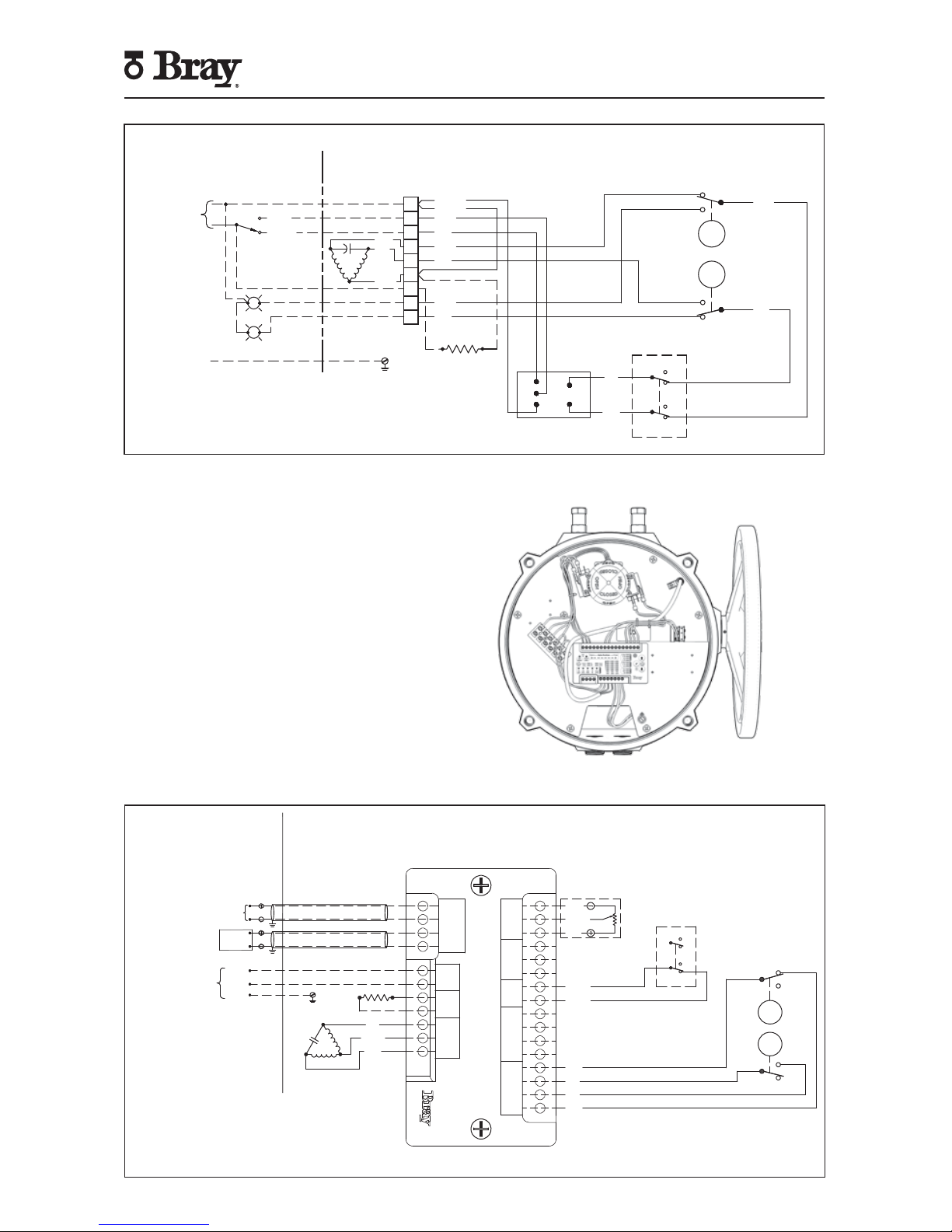
Figure 2 - S70 with I.R.B.
Page 7
5
Series 70 Electric Actuator
Installation, Operation and Maintenance Manual
Servo NXT
To control the actuator remotely from a process
controller in a modulating application, user must apply
the proper supply voltage and the configured control
signal to the Servo NXT electronics package. The control
signal may be applied locally from a hand-held signal
generator or remotely from a process controller.
For more information, please refer to the S70 Servo
NXT Manual. This manual is available on the company
website (bray.com).
Figure 4 - S70 with Servo NXT
FIELD WIRING ACTUATOR
SINGLE PHASE
POWER SUPPLY
GROUND
N
L
OPEN
BLUE
CLOSE
OPEN
CLOSE
(SEE NOTE 5)
FOR HEATER OPTION ONLY
RED
YELLOW OR
BLACK
O
C
N
MOTOR
YELLOW
YELLOW
RED
RED
RED
RED
BLUE
OVERRIDE SW
CLOSE
OPEN
RED
HEATER (OPTIONAL)
BLUE
BLUE
BLUE
BLUE
GREEN
CAM
RED
CAM
N.C.
COM
N.O.
N.C.
COM
N.O.
OPEN
CLOSE
COM
COM
N.C.
N.O.
N.C.
N.O.
CL
OP
N
MC
MO
INTERPOSING RELAY
1
2
3
4
5
6
7
8
9
Actuator shown in closed position
Figure 3 - Sample field wiring diagram for Series 70 actuator with I.R.B.
Actuator specific wiring diagram located inside actuator cover.
Figure 5 - Sample field wiring diagram for Series 70 actuator with Servo NXT.
Actuator specific wiring diagram located inside actuator cover.
FEEDBACK
POTENTIOMETER
WHITE
ORANGE
GREY
YELLOW
YELLOW
OVERRIDE SW
N.C.
N.O.
N.C.
N.C.
N.O.
N.O.
N.C.
N.O.
COM
COM
COM
COM
BLUE
BLUE
RED
RED
OPEN
CLOSE
GREEN
CAM
RED
CAM
COM
INPUT+
INPUT–
OUTPUT+
OUTPUT–
NEUTRAL
LIVE
NEUTRAL
CLOSE
LIVE
NEUTRAL
OPEN
WIPER
POWER
COM
CLOSE
COM
COM1
COM2
CLOSE
OPEN
COM1
COM2
CLOSE
OPEN
HW
OPEN
LIMIT SW
MOTOR
COMMAND
INPUT
POWER HEATER
HAND
WHEEL
CTRL BOX
FB POT
TORQUE SW
RED
YELLOW
OR BLACK
BLUE
HEATER
(OPTIONAL)
MOTOR
O
N
C
FIELD WIRING ACTUATOR
SHIELDED CABLE
OUTGOING FEEDBACK SIGNAL (SHIELDED)
INCOMING COMMAND SIGNAL
(SEE NOTES 5–7)
(SEE NOTES 6–8)
LOAD DEVICE
NOT TO EXCEED
400 OHMS
(4–20mA CONFIGURATION)
SINGLE PHASE
POWER SUPPLY
NEUTRAL
LIVE
GROUND
POSITION
FEEDBACK
DEVICE
Page 8
6
Series 70 Electric Actuator
Installation, Operation and Maintenance Manual
Storage
Actuators are not weatherproof unless they are
properly installed on the valve or prepared for storage.
Bray cannot accept responsibility for deterioration
caused on-site.
• Store units on a shelf or wooden pallet in order to
protect against floor dampness.
• Cover the units to protect against dust and dirt.
• To prevent condensation from forming inside these
units, maintain a near constant external temperature
and store in a well-ventilated, clean, dry room away
from vibration.
• For units with an internal heater, power should be
supplied to the heater via conduit entry with an
appropriate sealing gland.
Commissioning
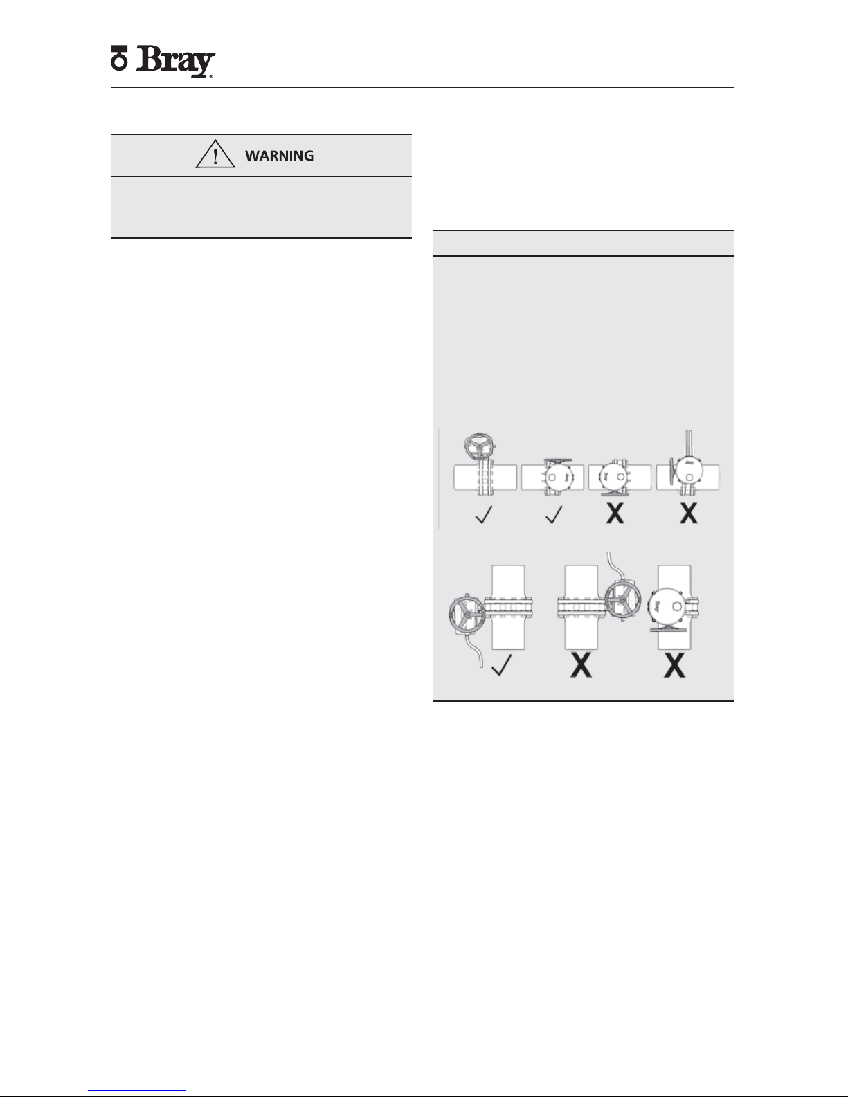
Mounting the Actuator
All Bray Series 70 electric actuators are suitable for
direct mounting on Bray butterfly valves. With proper
mounting hardware, the S70 actuator can be installed
onto other quarter-turn valves or devices.
NOTICE
The standard mounting position for the actuator
orients the unit with its handwheel in a vertical plane
and parallel to the pipeline.
If the actuator is mounted on a vertical pipe, it is
recommended that the unit be positioned with
the conduit entries on the bottom to prevent
condensation from entering the actuator through its
conduits.
In all cases, the conduit should be positioned
to prevent drainage into the actuator and the
handwheel should not be facing down.
Follow the steps below to mount the actuator onto
the valve.
1. Manually operate the actuator until the output shaft
of the actuator is in line with the valve stem. If
possible, select an intermediate position for both
the valve and actuator.
2. If required, place the proper adapter onto the valve
stem. It is recommended that a small amount of
‘anti-seize’ lubricant be applied to the adapter to
ease assembly.
3. Mount the actuator onto the valve stem.
4. Install the furnished mounting studs by threading
studs all the way into the actuator base. It may be
necessary to manually operate the actuator to align
the valve and actuator bolt patterns.
5. Fasten the mounting studs in place with furnished
hex nuts and lock washers
Page 9
7
Series 70 Electric Actuator
Installation, Operation and Maintenance Manual
Wiring the Actuator
Turn off all power and lockout/tag out service panel
before installing or modifying any electrical wiring.
1. Take the actuator cover off. The cover should be
kept on hand for reference.
2. Wire the actuator as per the wiring diagram attached
to the inside of the actuator cover.
NOTICE
Power and control wiring should use separate conduit
entries.
NOTICE
A minimum of 18 AWG wire is recommended for all
field wiring.
Terminals directly mounted on the actuator switch
plate accept wire sizes ranging from 14 to 22 AWG.
Terminals of internally mounted electronics modules
accept wire sizes ranging from 14 to 24 AWG.
NOTICE
The conduit connections must be properly sealed to
maintain the weatherproof integrity of the actuator
enclosure.
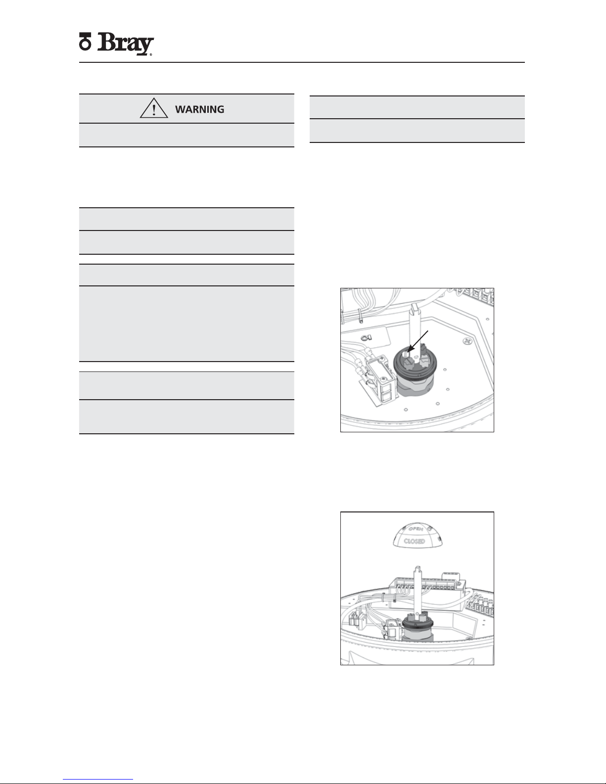
Setting Travel Limit Switches
NOTICE
If the unit came assembled to a valve, the switches
have been factory-set and DO NOT need adjustment.
Bray uses its patented cam design along with two SPDT
mechanical switches to set the ‘Open’ and ‘Closed’
position of the valve. The green cam actuates the ‘open’
switch when the actuator reaches the ‘open’ position.
Similarly, the red cam actuates the ‘closed’ switch when
the actuator reaches the ‘closed’ position.
Standard factory setting of the travel limit switches allows
90° travel between open and close positions. Cams for
each switch are adjustable for applications where less
than 90-degree travel is desired between the open and
closed positions.
Cam
Locking
Screw
Figure 6. Two SPDT Travel Limit Switches
Follow the steps below to adjust the travel limit cams.
NOTE: For Actuator Size 130, 180, ignore steps 1 and 10.
1. Remove the indicator rotor by pulling away from the
indicator shaft as shown in Figure 7.
Figure 7. Indicator rotor pulled up from the indicator shaft.
2. Manually operate the actuator clockwise until the
valve reaches the desired ‘closed’ position.
3. Loosen the cam locking screw shown in Figure 6.
Page 10
8
Series 70 Electric Actuator
Installation, Operation and Maintenance Manual
NOTICE
Cam locking screw must be slackened before cam
adjustments and re-tightened after cam adjustments.
Figure 8. Top view of the indicator shaft.
NOTE: It is possible that the rotation of one cam will
move the other cam. If this occurs, hold the other knobs
or cams during adjustment.
4. Rotate the red cam adjustment knob by hand or
with a flat head screwdriver until the red cam lobe
just activates (depresses) the ‘closed’ switch from a
clockwise direction.
NOTE: If fixed auxiliary switches are installed, the auxiliary
cam will activate prior to the main cam.
5. Tighten the cam locking screw.
6. Manually operate the actuator counterclockwise until
the valve reaches the desired ‘open’ position.
7. Loosen the cam locking screw.
8. Rotate the green cam adjustment knob until the green
cam lobe activates (depresses) the ‘open’ switch from
a counterclockwise direction.
9. Tighten the cam locking screw.
10. Place the indicator rotor back on the indicator shaft.
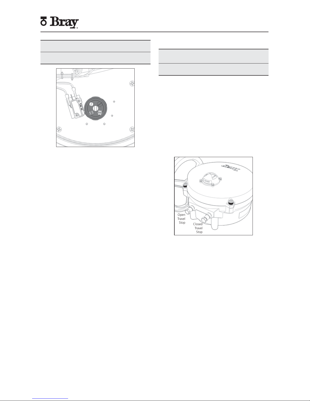
Setting Mechanical Travel Stops
NOTICE
If the unit came assembled to a valve, the stops have
been factory-set and DO NOT need adjustment.
Mechanical travel stops are designed to prevent over
travel while manually operating the actuator. They are
not designed to stop the electric motor.
Mechanical travel stops are located outside of the
actuator base for easy readjustment. Stainless steel lock
nuts with O-ring seals hold the travel stops securely in
place. Travel stop spacers are used to ensure that travel
stop bolts are not engaged to where they could limit 0°
to 90° electrical operation.
NOTE: Actuator Size 130, 180 does not use travel stop
spacers.
Open
Travel
Stop
Closed
Travel
Stop
Figure 9. Mechanical Travel Stops (CW Close).
Follow the steps below to set the mechanical travels
stops.
1. Manually drive the actuator to the ‘closed’ position.
2. Once the actuator is in the ‘closed’ position, rotate
the handwheel clockwise:
• ½ turn for Actuator Size 003, 006.
• 1 turn for Actuator Size 008, 012, 020.
• ½ turn for Actuator Size 030, 050, 065.
• 2 turns for Actuator Size 130, 180.
3. Adjust the ‘closed’ travel stop bolt until the travel
stop spacer is fully engaged or the travel stop bolt
contacts the output segment gear.
Page 11

9
Series 70 Electric Actuator
Installation, Operation and Maintenance Manual
4. Lock the travel stop bolt in position with the locknut.
5. Manually drive the actuator to the ‘open’ position.
6. Once the actuator is in the ‘open’ position, rotate
the handwheel counterclockwise
• ½ turn for Actuator Size 003, 006.
• 1 turn for Actuator Size 008, 012, 020.
• ½ turn for Actuator Size 030, 050, 065.
• 2 turns for Actuator Size 130, 180.
7. Adjust the ‘open’ travel stop bolt until the travel
stop spacer is fully engaged or the travel stop bolt
contacts the output segment gear.
8. Lock the travel stop bolt in position with the locknut.
Page 12

10
Series 70 Electric Actuator
Installation, Operation and Maintenance Manual
Disassembly and Assembly
Turn off all power and lockout/tag out service panel
before installing or modifying any electrical wiring.
1. Disconnect external wiring from terminals.
2. Disconnect motor wires from the main terminal
strip (motor neutral, open, and close)
NOTICE
Removal of switch plate with torque switches will
void warranty.
3. To remove the switch plate:
a. Follow after disconnecting external wires and
motor wires.
b. Unscrew the seven Phillips head mounting
screws.
c. Lift the switch plate(s) out as an assembly with
the indicator shaft attached.
d. NOTE: Do not misplace shaft coupler, insert,
or mounting screws.
Figure 10. S70, Actuator Size 003, 006 – switch plate removed.
4. To replace the switch plate:
a. Engage handwheel.
b. Place insert into the worm segment.
c. Place and center shaft coupler onto insert.
d. Align indicator shaft with groove in coupler
and gently place switch plate into position.
e. Check alignment of override switch activation
pin.
f. Slowly turn handwheel to ensure that the
indicator shaft is fully engaged in coupler.
g. Secure the switch plate with seven Phillips
head mounting screws in a “star” pattern.
h. Disengage the handwheel.
5. To remove the indicator shaft from the switch plate:
a. Follow after removing the switch plate.
b. Remove the retaining ring from the shaft,
located underneath switch plate.
c. Press the shaft out, from the bottom of the
switch plate.
d. NOTE: Provide support to top of switch plate
so that components on top of the switch plate
are not damaged during this procedure.
6. To remove the bearing from the switch plate:
a. Follow after the removing the indicator shaft.
b. Press the bearing from the top of the switch
plate to remove the bearing.
c. To replace, press bearing (700000-72701534)
into switch plate from the bottom of switch
plate.
7. To replace the indicator shaft in the switch plate:
a. Gently press the indicator shaft from the top of
the switch plate until the cams are flush with
the top surface of the switch plate. NOTE:
Provide support for the press fit bearing during
this step.
b. Replace retaining ring (070375-74503534) on
the shaft, located underneath switch plate.
c. Gently press the indicator shaft from the
bottom until the retaining ring is flush with
bottom of the bearing.
d. Test indicator shaft for tight fitment and ease
of rotation.
8. Other switch plate components:
a. Most components can be removed from the
switch plate without removal of the switch
plate.
Page 13

11
Series 70 Electric Actuator
Installation, Operation and Maintenance Manual
NOTE: Override switch assemblies are typically only
removable after the switch plate has been removed.
A specialty (short or 90°) screwdriver could be used
for disassembly when the switch plate is still attached
to the actuator base.
Figure 11. S70, Actuator Size 003, 006 – switch plate exploded view.
9. To remove the gear motor:
a. Follow after removing the switch plate.
b. Disconnect the motor leads which run to the
capacitor (120/220VAC motors).
c. For Actuator Size 003, 006, unscrew the
mounting screws (two lower, one upper).
d. For Actuator Size 008, 012, 020, unscrew
the mounting screws (four lower, one upper).
e. For Actuator Sizes 030 - 180, unscrew the
mounting screws (five lower, one upper).
f. Remove the motor vertically out of the unit.
NOTE: Do not misplace the alignment pin(s),
mounting screws or lockwashers.
10. To replace the gear motor:
a. Replace alignment pin (070612-71904520).
b. Place motor into housing and align motor with
worm shaft spur gear.
c. Secure the motor with mounting screws and
lockwashers in a “star” pattern.
d. Manually operate actuator to ensure proper
alignment.
e. Connect motor leads to capacitor (PSC motors
only).
Figure 12. S70, Actuator Size 003, 006 – motor removed.
11. To remove the worm shaft spur gear:
a. Follow after removing the gear motor.
b. For Actuator Size 003, 006:
i. Remove spring pin using a 3/32” [2.0 mm]
punch.
ii. Slide the gear off the end of the worm shaft.
c. For Actuator Size 008, 012, 020:
i. Remove spiral retaining ring
ii. Remove dowel pin with 3/16” [4.5 mm]
punch.
iii. Slide the gear off the end of the worm shaft.
d. For Actuator Sizes 030 - 180:
i. Remove bowed E-clip retaining ring.
ii. Slide the gear off the end of the worm shaft.
iii. Remove key
12. To replace the worm shaft spur gear:
a. Slide the gear onto the end of the worm shaft.
b. For Actuator Size 003, 006:
i. Slide the gear (700006-75511520) onto
the end of the worm shaft.
ii. Align the mounting hole on the gear and
the shaft.
iii. Use a 3/32” [2.0 mm] punch to replace the
slot spring pin (070412-71900520).
c. Actuator Size 008, 012, 020:
i. Slide the gear (700012-75511520) onto
Page 14

12
Series 70 Electric Actuator
Installation, Operation and Maintenance Manual
the end of the worm shaft.
ii. Align the mounting hole on the gear and
shaft.
iii. Use a 3/16” [4.5 mm] punch to replace the
dowel pin (070612-71804520).
iv. Replace the spiral retaining ring (070812-
74518520).
d. Actuator Sizes 030 - 180:
i. Rotate the handwheel so that the keyway
is visible and facing upwards.
ii. Replace key (700030-73100901).
iii. Slide the gear (700030-75503520) onto
the worm shaft.
iv. Replace bowed E-clip retaining ring
(070625-74511529).
13. To remove the output drive worm wheel:
a. Follow after removing the switch plate.
b. Back off both mechanical travel stops.
c. Remove the retaining ring and thrust washer
from the bottom of the base.
d. Lift the output drive worm wheel out of its
base.
Figure 13. S70, Actuator Size 003, 006 – output drive worm wheel
and spur gear removed.
14. To replace the output drive worm wheel:
a. Ensure worm wheel contains o-ring and is in
good condition.
b. Ensure that o-ring and worm wheel teeth are
lubricated with grease.
c. Place the worm wheel into the base, meshing
teeth with worm gear.
d. Replace thrust washer and retaining ring.
e. Engage handwheel and manually drive worm
wheel to ensure smooth operation.
f. Reset mechanical travel stops after switch plate
has been replaced.
15. To remove the handwheel:
a. Engage the handwheel.
b. Use a punch to remove the slot spring pin.
i. Actuator Size 003, 006: 3/32” [2.0 mm]
punch
ii. Actuator Size 008 - 180: 1/8” [3 mm] punch
c. Slide the handwheel off of the override shaft.
Figure 14. S70 with handwheel removed.
16. To replace the handwheel:
a. Engage the override shaft.
b. Slide the handwheel onto the override shaft
and align mounting holes.
c. Use a punch to fit a replacement slot spring pin.
i. Actuator Size 003, 006 slot spring pin:
070316-71900529
ii. Actuator Size 008, 012, 020 slot spring
pin: 070424-71900534
iii. Actuator Size 030, 050, 065-180 slot spring
pin: 070428-71900534
d. Disengage the handwheel.
Further disassembly of the unit requires special tools
and procedures, and thus will not be covered in this
manual.
Page 15

13
Series 70 Electric Actuator
Installation, Operation and Maintenance Manual
Field or Factory Installable Options
Auxiliary Switches
Auxiliary switch kits are a field or factory installable
option for all Series 70 actuators. Switch kits are
comprised of dry-contact (voltage free) SPDT mechanical
switches which are used to indicate travel position.
Switches are arranged into 2 stacks. For Actuator Size
003 - 065, stack 2 activates 3° prior to switches in
stack 1. For Actuator Size 130, 180, the switch that
activates 3° early depends on the direction of travel.
Auxiliary
Switches
Figure 15. Fixed auxiliary switches installed in a S70 actuator.
All Series 70 actuators can be fit with one set of fixed
auxiliary switches. These are a single set of switches
which activate 3° before the travel limit switches.
Adjustable auxiliary (Mid-Travel) switches can be fit
as single independent switches or in sets. If fitted as a
set, one of the switches in the set will activate 3° before
the other. Each switch set is activated independently
from other switch sets.
The maximum number and configuration of switches
depends on Actuator size and application of the Series
70 actuator. Terminal block availability due to installation
of other options may also limit the maximum number
of switches.
Switch Config.
for Modulating
Application
Actuator Size
003, 006
Actuator Size
008 thru 065
Actuator Size
130, 180
2 Limit Switches Standard Standard N/A
2 Limit, 2 Fixed 70A000-22901536 70A000-22901536 Standard
2 Limit, 2 Fixed, 1 Mid 70A006-22912536 70A012-22912536 70B180-22912536
2 Limit, 2 Fixed, 2 Mid N/A N/A N/A
2 Limit, 2 Fixed,
1 Set Mid
N/A 70A012-22914536 70B180-22914536
2 Limit, 2 Fixed,
2 Set Mid
N/A N/A N/A
Switch Config. for
On/Off Applications
Actuator Size
003, 006
Actuator Size
008 thru 065
Actuator Size
130, 180
2 Limit Switches Standard Standard N/A
2 Limit, 2 Fixed 70A000-22901536 70A000-22901536 Standard
2 Limit, 2 Fixed, 1 Mid 70A006-22902536 70A012-22902536 70B180-22902536
2 Limit, 2 Fixed, 2 Mid 70A006-22903536 70A012-22903536 70B180-22903536
2 Limit, 2 Fixed,
1 Set Mid
70A006-22904536 70A012-22904536 70B180-22904536
2 Limit, 2 Fixed,
2 Set Mid
N/A 70A012-22905536 70B180-22905536
Heater
Bray offers an optional heater as a field or factory
installable option for the Series 70 actuator to prevent
condensation from forming inside the actuator. This
PTC (Positive Temperature Coefficient) style heater
has a unique temperature - resistance characteristic.
The heater self-regulates by increasing its electrical
resistance relative to its temperature. The heater does
not require external thermostats or switches to control
its heat output.
Heater
Figure 16. Heater installed on a S70 switch plate.
NOTICE
The heater must have a constant power supply to be
effective
The heater surface can reach temperatures in excess
of 392°F [200°C].
Page 16

14
Series 70 Electric Actuator
Installation, Operation and Maintenance Manual
Heater Kit:
• Heater with flying leads
• Mounting Bracket
• #10 Pan Head Screw, Phillips Drive
Tools Required:
• Screwdriver, 3/16” [5 mm] tip flat blade
• Screwdriver, No.1 Phillips
Installation Procedure:
Turn off all power and lockout/tag out service panel
before installing or modifying any electrical wiring.
The heater is mounted through a hole provided in
the switch plate.
1. Place the heater snugly into its mounting bracket
until approx. 1/2 to 1” [13mm to 25 mm] is left
above the bracket.
2. Slip the heater into its mounting hole.
3. Align the fastening hole in the bracket with the
threaded screw hole in the plate and fasten the
heater to the switch plate.
4. Connect the heater wires to the terminal strip as
indicated on the wiring diagram.
Torque Switches
Mechanical Torque switches are a factory installed and
calibrated option available for all Series 70 actuators.
Installation is simple, but due to the requirement for
special calibration equipment, it is not available for
field installation. Modifying the factory torque setting
voids the actuator warranty. Removal of the switch
plate invalidates factory calibration
The worm is pinned to the worm shaft, which is held in
position with a stack of disc springs at both ends. The
torque transmitted through the worm to the output
worm gear acts directly against the disc springs, which
compress proportionately. The worm and worm shaft
shift axially as a result.
A specially designed drive lever and pin is incorporated
into a groove on the worm, providing the profile for the
torque switching mechanism. A drive lever & pin rides
in the worm gear torque sensor groove, and in turn
drives a cam. The cam then actuates its electrical switch,
which interrupts the power to the motor winding when
the torque exceeds the setting. The motor can still
be powered to run in the opposite direction. When
powered in the opposite direction, the tripped torque
switch will release automatically.
NOTICE
Torque switches are not field adjustable. Adjustment
of torque switches in the field will void warranty.
Removal of switch plate with torque switches in the
field will void warranty.
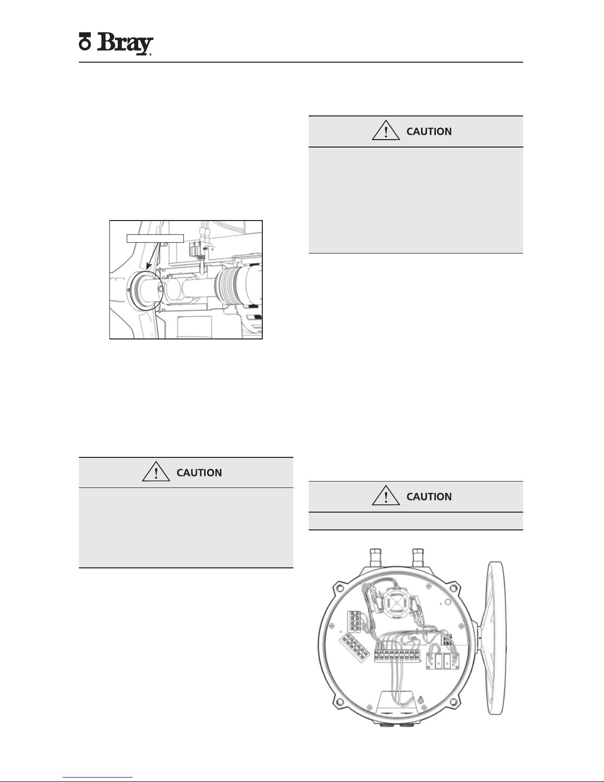
Local Control Station
The local control station is a field or factory installable
option that gives the operator the ability to locally drive
the Series 70 actuator with electrical power; overriding
the control signal from the process controller. The
control station has a red (closed) and green (open)
light to provide end-of-travel indication. It also has two
3-position switches as shown in Figure 17.
Figure 17. S70 with Control Station.
Switch 1 lets the operator choose between the following
three modes of operation:
1. Local: In this mode, using switch 2 the operator
can drive the actuator to open or close position,
or stop the actuator; overriding any control signal
from the process controller.
2. Off: In this mode, the actuator can only be operated
manually.
3. Remote: In this mode, the actuator is controlled
remotely from a process controller.
Control Station Kit
• Local Control Station Assembly
• #10-24UNC x 4.5” Socket Head Cap Screws
(Qty:4)
• O-rings (Qty:4)
• Gasket
• Wiring Diagram
Tools Required:
• Screwdriver, 3/16”[5 mm] tip flat blade
• Screwdriver, No.1 Phillips
• Hex Key, 5/32”
Page 17

15
Series 70 Electric Actuator
Installation, Operation and Maintenance Manual
Installation Procedure:
Turn off all power and lockout/tag out service panel
before installing or modifying any electrical wiring.
The local control station is mounted to the S70 against
the conduit openings using 4 pre-drilled and tapped
mounting holes.
1. Remove the S70 actuator cover and set aside in a
safe location.
2. Remove all conduit plugs and external connections
on the S70 that may already be in place.
3. Remove 4 short bolts and washers that were preinstalled on the exterior of the S70 base, surrounding
the conduit entries.
4. Adhere the gasket to the control station base.
5. Slide o-rings onto the long mounting bolts until
flush with bottom of bolt head.
6. Mount the control station to the actuator using the
4 mounting bolts.
7. Wire the control station to the actuator in accordance
to the wiring diagram provided.
NOTICE
Power and control wiring should use separate conduit
entries
NOTES:
• The local control station contains no terminal strips
and all wiring is direct to the switches and lights via
2 x ¾” NPT or holes in bottom of housing.
• Ordering the control station with optional pin
connector receptacles will eliminate the necessity
of field wiring. Not all possible options are available
with receptacles. Consult factory.
• Control station will be completely factory wired
and tested.
• Factory will need wiring diagram drawing number
of the existing unit if it is to be retrofit with a local
control station. New wiring diagram will be provided
based upon this information.
• Local control station can be ordered with key lockable
switches.
• Local control station requires a dedicated set of
auxiliary switches. These switches are required for
turning on or off the lights on the control station
to locally indicate actuator position.
• Alternative mounting kit can be ordered in case it is
preferred to mount the control station nearby but
not on the S70 actuator.
Battery Backup Unit
Bray offers a factory installable Battery Backup Unit
(BBU) for the 24 V Series 70 electric actuator.
In the event of power failure, the BBU will switch the
actuator to battery power to reach its fail position. After
the actuator has reached its fail position, the BBU goes
to ‘Standby Mode’ until external power is restored.
Once external power has been restored, the actuator
returns to the position corresponding to the control
signal present.
Figure 18. S70 with Battery Backup Unit.
Battery Backup Unit is available as a factory installable
option. For more information, please refer to the S70
24V Actuator with BBU Manual. This manual is available
on the company website (bray.com).
Page 18

16
Series 70 Electric Actuator
Installation, Operation and Maintenance Manual
Indication of Remote Control
Bray offers two field or factory installable kits to indicate
if a process controller has remote control of the Series
70 actuator. Remote control of the actuator can be
interrupted if the actuator handwheel has been left
engaged or if a local control station has been switched
out of remote mode.
A dry contact (voltage free) mechanical switch provides
indication if the handwheel is engaged. Alternatively, an
additional dry contact (voltage free) mechanical switch
can be placed in Local Control Station to provided
indication if the local control station is switched out
of remote mode. Both kits can be installed and wired
in series to provide dual indication. Dual indication
wiring is meant to indicate that remote control has
been interrupted and does not distinguish between
modes of interruption.
NOTE:
• Factory will need wiring diagram drawing
number and model of the existing unit if it is to
be retrofitted with a Remote Control Indication
kit. New wiring diagram will be provided based
upon this information.
• Some configurations may limit use of remote
control indication kits receptacles due to number
of wires entering through the conduit.
Spinner
A spinner is field or factory installable attachment to
the actuator handwheel to ease and speed the manual
operation of the Series 70 actuator. Actuator Size 003,
006 units mount the spinner on a lever which screws
onto the back of the handwheel. Actuator Size 008 - 180
units mount the spinner on the rim of the handwheel.
Figure 19. S70 with Handwheel Spinner Attached.
NOTICE
Care should be exercised in the use of a spinner
equipped handwheel.
Rapid operation of the handwheel to close the valve
may cause water hammer.
Rapid travel into a travel stop may cause damage.
Spinner Kit, Actuator Size 003, 006:
• Spinner and Lever Assembly
• #10-32UNF x 3/8” Flat Head Socket Cap.
Spinner Kit, Actuator Size 008 - 180:
• Spinner Handle
• ¼”-20UNC x ¾” Socket Head Shoulder Bolt
Tools Required:
• Hex Key, 1/8” (Actuator Size 003, 006)
• Hex Key, 3/16” (Actuator Sizes 008 - 180)
Installation Procedure:
• For Actuator Size 003, 006 – Position the lever onto
the back of the handwheel then screw the flat head
cap screw in to place from behind.
• For Actuator Size 008, 012, 020-180 – Place the
socket head shoulder bolt through the spinner
handle and screw it firmly into the handwheel rim.
Receptacles (Quick Connectors)
Bray offers plug-in receptacles as a field or factory
option for quick and easy field wiring of Series 70
actuators. Cord sets to fit these connectors can also
be ordered in several lengths.
Unless otherwise specified, power receptacles will be
5-pin mini style, standard duty with a black anodized
aluminum finish. They conform to ANSI B93.55M except
in wire color. Euro receptacles will be used for low
power instrument and signal cable since they can be
supplied shielded.
Wiring diagrams for plug-in receptacles for either the
Bray Series 70 or the local control station will be provided
as a separate diagram. Units ordered with pin connector
receptacles factory installed are wired and tested
Receptacle Kit:
• Receptacle(s), male pin and male thread ½” NPT
[M20], in the quantity, style, and number of pins
ordered
• Reducing bushing ¾” to ½” NPT [M25 to M20] for
installation in Actuator Sizes 008 - 180 and control
stations
• Wiring Diagram
Tools Required:
• Screwdriver, 3/16” [5 mm] tip flat blade
• Wrench, 1” [25mm]
Page 19

17
Series 70 Electric Actuator
Installation, Operation and Maintenance Manual
Figure 20. S70 with 5-pin receptacle and corresponding cord set.
Installation Procedure:
1. Screw the receptacle into the actuator conduit entry
using Teflon tape or similar.
2. Wire to the terminal strip according to the wiring
diagram or the field wiring requirements.
NOTES:
• Euro receptacles use 22 AWG wire rated at 250V,
4 Amp. Pin configuration interfaces with European
standards.
• Mini Receptacles use 18 AWG wire rated at 300V, 9
Amp. Pin configuration conforms to ANSI B93.55M.
• Factory will need wiring diagram drawing number
and model of the existing unit if it is to be retrofit with
receptacles. New wiring diagram will be provided
based upon this information.
• Some configurations may limit use of receptacles due
to number of wires entering through the conduit.
External Signal Feedback Potentiometer
Potentiometers are a field or factory installable option
for continuous duty actuators. Actuators which are
not continuous duty do not have a pot gear fitted
on their indicator shafts and must be fitted with a
new indicator shaft in the factory. S70 actuators fitted
with electronics for modulating applications already
fit a potentiometer and cannot fit a second. In this
case, retransmission of position is provided through
the modulating electronics package.
Feedback Potentiometer Kit:
• Potentiometer Assembly
• #6 Cross Drive Pan Head Screws (Qty:2)
• #6 Internal Lockwashers (Qty:2)
• 4-pole Terminal Strip
• Terminal Strip Marker
• Wiring Diagram
Tools Required:
• Screwdriver, 3/16” [5 mm] tip flat blade
• Screwdriver, No.2 Phillips
Figure 21. S70 Potentiometer installation.
1. Orient the actuator in the full open (counter
clockwise) position.
2. Install the potentiometer next to the indicator
shaft where two threaded holes are provided for
installation.
3. Align the raised green rib on pot gear with the
center line of the indicator shaft.
4. Push the assembly towards the cam to mesh the
gears, then tighten the mounting screws.
5. Rotate the actuator handwheel so that the red cam
lobe is facing the body of the potentiometer. Make
sure that the cam is not touching the potentiometer
assembly. Readjust the assembly position if necessary.
6. Cut the terminal marker to fit the 4-pole terminal
strip.
7. Mount the 4-pole terminal strip and marker on the
switch plate.
8. Wire the potentiometer to the terminal strip using
the new wiring diagram.
9. Adhere the new wiring diagram sticker to the inside
of the cover.
NOTE:
• Factory will need wiring diagram drawing number
and model of the existing unit if it is to be retrofit
with a potentiometer. New wiring diagram will be
provided based upon this information.
Raised
green rib
Page 20

18
Series 70 Electric Actuator
Installation, Operation and Maintenance Manual
Basic Tools
Common To All Units
Terminal connections, cam adjustment Screwdriver,
1
⁄4" [6 mm] flat tip blade
All switches, terminal strip, torque switch plate Screwdriver, No.1 Phillips
Switch plate screws, capacitor Screwdriver, No. 2 Phillips
Actuator Size 003, 006
Mounting nuts Wrench,
1
⁄2" Wrench, M8
Cover captivated capscrews Hex key, 1⁄4" Hex Key, M8
Travel stop adjusting bolts and jam nuts Wrench, 7⁄16" Wrench, M6
Motor mount socket flat head capscrew Hex key,
3
⁄32"
Motor mount socket head capscrew Hex key,
9
⁄64"
Conduit Entry Plug (
1
⁄2” NPT) Hex key, 3⁄8” Hex Key, M20
Actuator Size 008, 012, 020
Mounting nuts (small pattern) Wrench,
1
⁄2” Wrench, M8
Mounting nuts (large pattern) Wrench,
3
⁄4" Wrench, M12
Cover captivated capscrews Hex key,
5
⁄16" Hex Key, M10
Travel stop adjusting bolts and jam nuts Wrench,
9
⁄16" Wrench, M10
Motor mount socket head capscrew Hex key,
5
⁄32"
Conduit Entry Plug (
3
⁄4” NPT) Hex key, 9⁄16” Hex Key, M25
Actuator Size 030, 050, 065
Mounting nuts (small pattern) Wrench,
3
⁄4” Wrench, M12
Mounting nuts (large pattern) Wrench, 11⁄8” Wrench, M20
Cover captivated capscrews Hex key,
3
⁄8" Hex Key, M20
Travel stop adjusting bolts and jam nuts Wrench,
3
⁄4” Wrench, M12
Motor mount socket head shoulder bolt Hex key,
5
⁄32” Hex Key, M12
Motor mount socket head capscrews Hex key,
3
⁄16"
Conduit Entry Plug (
3
⁄4” NPT) Hex key, 9⁄16” Hex Key, M25
Actuator Size 130, 180
Mounting nuts (small pattern) Wrench,
3
⁄4” Wrench, M12
Mounting nuts (large pattern) Wrench, 1
1
⁄8” Wrench, M20
Cover captivated capscrews Hex key,
3
⁄8” Hex Key, M12
Travel stop adjusting bolts Wrench,
5
⁄16” Wrench, M25
Motor mount socket head shoulder bolt Hex key,
5
⁄32”
Motor mount socket head capcrews Hex key,
3
⁄16”
Conduit Entry Plug (
3
⁄4” NPT) Hex key, 9⁄16” Hex Key, M25
Appendix A
Page 21

19
Series 70 Electric Actuator
Installation, Operation and Maintenance Manual
Actuator Troubleshooting Chart
Appendix B
Problem Possible Cause Solutions
Actuator does not operate
Override is engaged Push handwheel in all the way
Wiring is incorrect Check wiring and power supply
Actuator motor has reached its
thermal shutdown temperature
Allow time to cool
Actuator operates in
reverse directions
Field wiring is reversed Rewire field wiring
Actuator does not fully
close valve (or open valve)
Limit switches are depressed Readjust travel limit switches
Mechanical travel stop is stopping
actuator
Adjust mechanical travel stops
Valve torque requirement is higher
than actuator output
Manually override out of seat, try angle
seating or larger actuator
Optional torque switches are
activating
Valve torque exceeds actuator torque
rating - consult factory
Voltage power supply is low Check power source.
Engaging override
handwheel does not shut
off motor
Override pin is corroded or
damaged
Clean and check for smooth operation of
the override switch pin
Override switch is damaged Replace switch
Disengaging override
hand-wheel does not
restart motor
Not completely disengaged
Push handwheel in as far as possible (no
yellow showing)
Override pin is damaged or and
does not activate switch
Replace override pin
Incorrect wiring of override switch Check wiring
Motor runs but worm and
gear segment do not
Worm gear segment is not
meshing with worm
Remove switch plate and inspect, adjust
travel stops to prevent gear disengaging
Pin/Key on Worm/Motor drive
gear sheared
Replace Pin/Key on drive gear
Corrosion inside unit
Condensation forming
Test heater wiring, should have constant
power
Water leaking in
Check all seals and possible water entry
through conduit
Page 22

20
Series 70 Electric Actuator
Installation, Operation and Maintenance Manual
Series 70 – Size 003, 006 – Electric Actuator Exploded View
26
4140
34 35 36 38 39
45
47475154
58
64
70
73
72
71
44505649
61
27
53
57
62
4646
16
15
7
6
5
4
3
24
23
9
8
10
1
12
17
11
13
20
19
18
55
65
63
42 43
464852 48
68
29 30 31 32 33
22
69
67
28
60
59
- Item 74 is optional.
- Items 15, 16 and 17 are optional.
- Item 22 is installed in units when
torque switches are not required.
66
25
37
2
14
21
74
46
Page 23

21
Series 70 Electric Actuator
Installation, Operation and Maintenance Manual
Item
No.
Description
1 Indicator Cover Screws
2 Lockwasher
3 Position Indicator Cover
4 O-Ring
5 Cover Fastening Screws
6 Cover
7 O-Ring
8 Position Indicator
9 Cam Assembly
10 Limit Switch Screw
11 Limit Switch Bracket
12 Main Open/Closed Limit Switches
13 Limit Switch Insulator
14 Switch Plate, Fixed
15 Heater Bracket Screw
16 Heater Mounting Bracket
17 Heater
18 Override Switch
19 Override Switch Insulator
20 Override Switch Screw
21 Override Switch Trigger Pin
22 Torque Switch Cover
23 Switch Plate Ball Bearing
24 Retaining Ring
25 Coupler
26 Worm Wheel
27 Spring Pin
28 O-Ring
29 O-Ring
30 Nylon Flat Washer
31 Travel Stop Nut
32 Travel Stop Spacer
33 Travel Stop Bolt
34 Worm Shaft
35 Override Drive Pin
36 Spring Plunger
37 Manual Override Shaft Hub
Item
No.
Description
38 Manual Override Shaft Stub
39 Manual Override Sleeve
40 O-Ring
41 O-Ring
42 Retaining Ring
43 Handwheel
44 Spring Pin
45 Manual Override Bushing
46 Thrust Washer
47 Thrust Roller Bearing
48 Disc Spring
49 Worm
50 Spring Pin
51 Retaining Ring
52 Thrust Washer
53 Base
54 Conduit Plug
55 Name Tag
56 Bushing
57 Drive Gear Pin
58 Drive Gear
59 Terminal Strip
60 Capacitor
61 Gearmotor
62 Lock Washer
63 Motor Cap Screw
64 Wire Entry Guard
65 Dowel Pin
66 Motor Screw
67 Ground Terminal Washer
68 Ground Terminal Screw
69 Switch Plate Mounting Screw
70 Removable Switch Plate
71 Terminal Strip Marker
72 Terminal Strip
73 Terminal Block Screw
74 Aux Open/Closed Limit Switches
Page 24

22
Series 70 Electric Actuator
Installation, Operation and Maintenance Manual
Series 70 – Size 008, 012, 020 – Electric Actuator Exploded View
45
70
68
69
67
63
61
59 58 57 56 485054
42414036
26
16
17
18
65
27
30
37 44
475155
64
43
62
49515049
38
52535352
31 32 33 34 35
71
72
73
76
77
9
8
6
5
4
3
2
1
12
13
14
15
10
11
24
23
22
21
20
75
74
25
66
28
29
39
19
- Item 77 is optional.
- Items 16, 17 and 18 are optional.
- Item 76 is installed in units when
torque switches are not required.
46
60
7
Page 25

23
Series 70 Electric Actuator
Installation, Operation and Maintenance Manual
Item
No.
Description
1 Indicator Cover Screws
2 Lockwasher
3 Position Indicator Cover
4 O-Ring
5 Cover Fastening Screw
6 Cover
7 O-Ring
8 Position Indicator
9 Cam Assembly
10 Switch Plate Mounting Screw
11 Switch Plate
12 Limit Switch Screw
13 Limit Switch Bracket
14 Main Open/Closed Limit Switches
15 Limit Switch Insulator
16 Heater Bracket Screw
17 Heater Mounting Bracket
18 Heater
19 Override Switch Trigger Pin
20 Override Switch
21 Override Switch Insulator
22 Override Switch Screw
23 Switch Plate Ball Bearing
24 Retaining Ring
25 Coupler
26 Worm Wheel
27 O-Ring
28 Terminal Strip
29 Capacitor
30 Spring Pin
31 O-Ring
32 Nylon Flat Washer
33 Travel Stop Nut
34 Travel Stop Spacer
35 Travel Stop Bolt
36 Worm Shaft
37 Override Drive Pin
38 Spring Pin
Item
No.
Description
39 Manual Override Shaft Hub
40 Spring Plunger
41 Manual Override Shaft Stub
42 Manual Override Sleeve
43 O-Ring
44 O-Ring
45 Retaining Ring
46 Handwheel
47 Spring Pin
48 Manual Override Bushing
49 Thrust Washer
50 Thrust Roller Bearing
51 Thrust Washer
52 Disc Spring
53 Disc Spring
54 Worm
55 Spring Pin
56 Retaining Ring
57 Thrust Washer
58 Base
59 Conduit Plug
60 Name Tag
61 Bushing
62 Gear Spacer
63 Drive Gear
64 Spring Pin
65 Retaining Ring
66 Gearmotor
67 Lock Washer
68 Motor Cap Screw
69 Dowel Pin
70 Wire Entry Guard
71 Terminal Strip Marker
72 Terminal Strip
73 Terminal Block Screw
74 Ground Terminal Washer
75 Ground Terminal Screw
76 Torque Switch Cover
77 Aux Open/Closed Limit Switches
Page 26

24
Series 70 Electric Actuator
Installation, Operation and Maintenance Manual
Series 70 – Size 030, 050, 065 – Electric Actuator Exploded View
7
8
72
43 44 45 47
56575859
67
66
68
70
75
73
69
14
15
16
18
19
24
26
28
29
30
38 42
20
27
9
23
3
1
2
5
76
6
36
25
12
13
77
11
10
4
64
63
61
60
49 50 51 52 53 55 54 53 52 51 50 49 48
4039 4137
31 32 33
34
35
74
- Item 77 is optional.
- Items 14, 15 and 16 are optional.
- Item 76 is installed in units when
torque switches are not required.
71
21
22
46
65
62
17
Page 27

25
Series 70 Electric Actuator
Installation, Operation and Maintenance Manual
Item
No.
Description
1 Indicator Cover Screws
2 Lockwasher
3 Position Indicator Cover
4 O-Ring
5 Cover Fastening Screw
6 Cover
7 O-Ring
8 Position Indicator
9 Cam Assembly
10 Limit Switch Screw
11 Limit Switch Bracket
12 Main Open/Closed Limit Switches
13 Limit Switch Insulator
14 Heater Bracket Screw
15 Heater Mounting Bracket
16 Heater
17 Override Switch Trigger Pin
18 Override Switch
19 Override Switch Insulator
20 Override Switch Screw
21 Ground Terminal Screw
22 Ground Terminal Washer
23 Switch Plate Ball Bearing
24 Retaining Ring
25 Coupler
26 Worm Wheel
27 O-Ring
28 Capacitor
29 Terminal Strip
30 Spring Pin
31 O-Ring
32 Nylon Flat Washer
33 Travel Stop Nut
34 Travel Stop Spacer
35 Travel Stop Bolt
36 Worm Shaft
37 Override Drive Pin
38 Manual Override Shaft Hub
Item
No.
Description
39 Spring Pin
40 Spring Plunger
41 Manual Override Shaft
42 Manual Override Sleeve
43 O-Ring
44 O-Ring
45 Retaining Ring
46 Spring Pin
47 Handwheel
48 Manual Override Bushing
49 Thrust Washer
50 Thrust Roller Bearing
51 Thrust Washer
52 Spherical Washer
53 Disc Spring
54 Worm
55 Spring Pin
56 Retaining Ring
57 Thrust Washer
58 Base
59 Conduit Plug
60 Name Tag
61 Bushing
62 Drive Gear Key
63 Drive Gear
64 Retaining Ring
65 Gear Motor
66 Dowel Pin
67 Lock Washer
68 Motor Cap Screw
69 Motor Shoulder Screw
70 Wire Entry Guard
71 Terminal Strip Marker
72 Terminal Strip
73 Terminal Block Screw
74 Switch Plate
75 Switch Plate Mounting Screw
76 Torque Switch Cover
77 Aux Open/Closed Limit Switches
Page 28

26
Series 70 Electric Actuator
Installation, Operation and Maintenance Manual
Series 70 – Size 130, 180 – Electric Actuator Exploded View
47484950
51
54
57
58
59
60
61
62
64
63
65
66
67
68
26
25
24
23
22
21
19
18
11
15
14
13
12
10
8
69
70
4
2
17
56
27 28 29 30 31 33 34 35 36 37
40 41 42 43 46 45
43 42 41 40 39
38
52
53
55
1
32
16
9
6
7
7
6
5
3
- Items 12, 13 and 14 are optional.
44 44
20
Page 29

27
Series 70 Electric Actuator
Installation, Operation and Maintenance Manual
Item
No.
Description
1 Cover Fastening Screw
2 Cover
3 O-Ring
4 Limit Switch Screw
5 Flat Insulation Washer
6 Main Open/Closed Limit Switches
7 Aux Open/Closed Limit Switches
8 Switch Spacer
9 Limit Switch Insulator
10 Torque Switch Assembly
11 Override Switch Trigger Pin
12 Heater Bracket Screw
13 Heater Mounting Bracket
14 Heater
15 Override Switch
16 Override Switch Insulator
17 Override Switch Screw
18 Switch Plate Ball Bearing
19 Retaining Ring
20 Coupler
21 Worm Wheel
22 O-Ring
23 Capacitor
24 Terminal Strip
25 Spring Pin
26 Set Screw
27 Worm Shaft
28 Override Drive Pin
29 Manual Override Shaft Hub
30 Spring Pin
31 Spring Plunger
32 Manual Override Shaft Stub
33 Manual Override Sleeve
34 O-Ring
35 O-Ring
36 Retaining Ring
Item
No.
Description
37 Spring Pin
38 Handwheel
39 Manual Override Bushing
40 Thrust Washer
41 Thrust Roller Bearing
42 Thrust Washer
43 Spherical Washer
44 Disc Spring
45 Worm
46 Spring Pin
47 Retaining Ring
48 Thrust Washer
49 Base
50 Conduit Plug
51 Name Tag
52 Bushing
53 Drive Gear Key
54 Drive Gear
55 Retaining Ring
56 Gear Motor
57 Lock Washer
58 Motor Cap Screw
59 Dowel Pin
60 Motor Shoulder Screw
61 Wire Entry Guard
62 Ground Terminal Washer
63 Switch Plate Mounting Screw
64 Ground Terminal Screw
65 Switch Plate
66 Terminal Strip Marker
67 Terminal Strip
68 Terminal Block Screw
69 Cam Assembly
70 Bushing
Page 30

28
Series 70 Electric Actuator
Installation, Operation and Maintenance Manual
1
9
7
8
6
21
20
19
13
16
18
17
15
14
12
11
10
4
3
2
13
14
5
3: 1 GEAR BOX
EXPLODED VIEW
ITEM NO.
DESCRIPTION
1
FASTENING SCREW
2
POSITION INDICATOR PLATE
3
POSITION INDICATOR GASKET
4
ACTUATOR/GEAR BOX GASKET
5
DOWEL PIN
6
O-RING
7
WASHER,FLAT,NYLON
8
NUT,HEX
9
BOLT,HEX HD
10
COVER
11
WASHER, CONICAL
12
ACTUATOR/GEAR BOX FASTENING SCREW
13
OUTPUT GEAR BEARING
14
IDLER/INPUT GEAR BEARING
15
COVER GASKET
16
INPUT GEAR
17
OUTPUT GEAR
18
IDLER GEAR
19
COVER
20
LOCK WASHER
21
BASE FASTENING SCREW
Series 70 – Size 130, 180 – 3:1 Gear Box Exploded View
Page 31

29
Series 70 Electric Actuator
Installation, Operation and Maintenance Manual
Item
No.
Description
1 Fastening Screw
2 Position Indicator Plate
3 Position Indicator Gasket
4 Actuator/Gear Box Gasket
5 Dowel Pin
6 O-Ring
7 Washer,Flat,Nylon
8 Nut,Hex
9 Bolt,Hex Hd
10 Cover
11 Washer, Conical
12 Actuator/Gear Box Fastening Screw
13 Output Gear Bearing
14 Idler/Input Gear Bearing
15 Cover Gasket
16 Input Gear
17 Output Gear
18 Idler Gear
19 Cover
20 Lock Washer
21 Base Fastening Screw
Page 32

All statements, technical information, and recommendations in
this bull etin are for ge neral use onl y. Consult Bray repre sentativ es
or factory for the specific requirements and material selection
for your intended application. The right to change or modify
produc t design or product without prior notice is reserved.
Patents issued and applied for worldwide.
Bray
®
is a registered trademark of BRAY INTERNATIONAL, Inc.
© 2017 Bray International. All rights reserved.
IOM-70 – 07_31_2017
HEADQUARTERS
Bray International, Inc.
13333 Westland East Blvd.
Houston, Texas 77041
Tel: 281.894.5454
bray.com
THE HIGH PERFORMANCE COMPANY
BRAY INTERNATIONAL
PRIMARY SALES AND SERVICE LOCATIONS
USA
Houston, Texas
CHINA
Hangzhou, Zhejiang
MEXICO
Zapopan, Jalisco
RUSSIA
Moscow
AFRICA
Johannesburg
COLOMBIA
Bogotá
MIDDLE EAST
Dubai
SINGAPORE
Ubi Techpark
BENELUX
Heerhugowaard
FRANCE
Voiron
PACIFIC
Melbourne, Australia
SOUTH KOREA
Seoul
BRAZIL
Paulinia, Sao Paulo
GERMANY
Krefeld
PERU
Lima
SOUTHEAST ASIA
Malaysia
CANADA
Montreal
INDIA
Vadodara
POLAND
O´swi¸ecim
UNITED KINGDOM
Glasgow
CHILE
Santiago
ITALY
Milano
FLOW-TEK RITE CORPORATION AMRESIST KUGELHAHN MÜLLER
USA
Houston, Texas
CANADA
Montreal
USA
Houston, Texas
GERMANY
Krefeld
BRAZIL
Paulinia, Sao Paulo VALVTRONIC BRAY/VAAS
CHINA
Hangzhou, Zhejiang
ARGENTINA
Buenos Aires
INDIA
Chennai
 Loading...