

Page 1
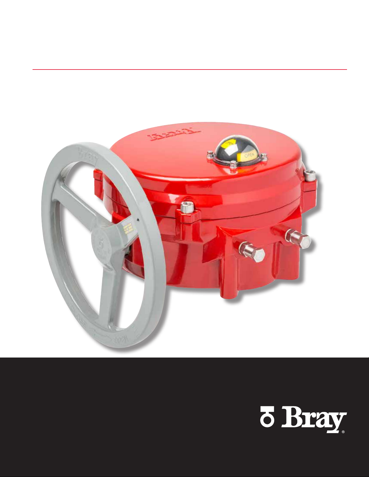
SERIES 70
ELECTRIC ACTUATORS
TECHNICAL MANUAL
THE HIGH PERFORMANCE COMPANYBRAY.COM
Page 2
SERIES 70 ELECTRIC ACTUATOR
Technical Manual - Table of Contents
Specifications . . . . . . . . . . . . . . . . . . . . . . . . . . . . . . . . . . . . . . . . . . . . . . . . . 3
Battery Backup Unit (BBU) 24V Specifications . . . . . . . . . . . . . . . . . . . . . . . . . . . . . . . . . 4
Torque and Motor Data . . . . . . . . . . . . . . . . . . . . . . . . . . . . . . . . . . . . . . . . . . . . 5
Actuator Mounting . . . . . . . . . . . . . . . . . . . . . . . . . . . . . . . . . . . . . . . . . . . . . . 6
Imperial (in) . . . . . . . . . . . . . . . . . . . . . . . . . . . . . . . . . . . . . . . . . . . . . . . . . . 6
Metric (mm). . . . . . . . . . . . . . . . . . . . . . . . . . . . . . . . . . . . . . . . . . . . . . . . . . 6
Standard Drawings . . . . . . . . . . . . . . . . . . . . . . . . . . . . . . . . . . . . . . . . . . . . . . 7
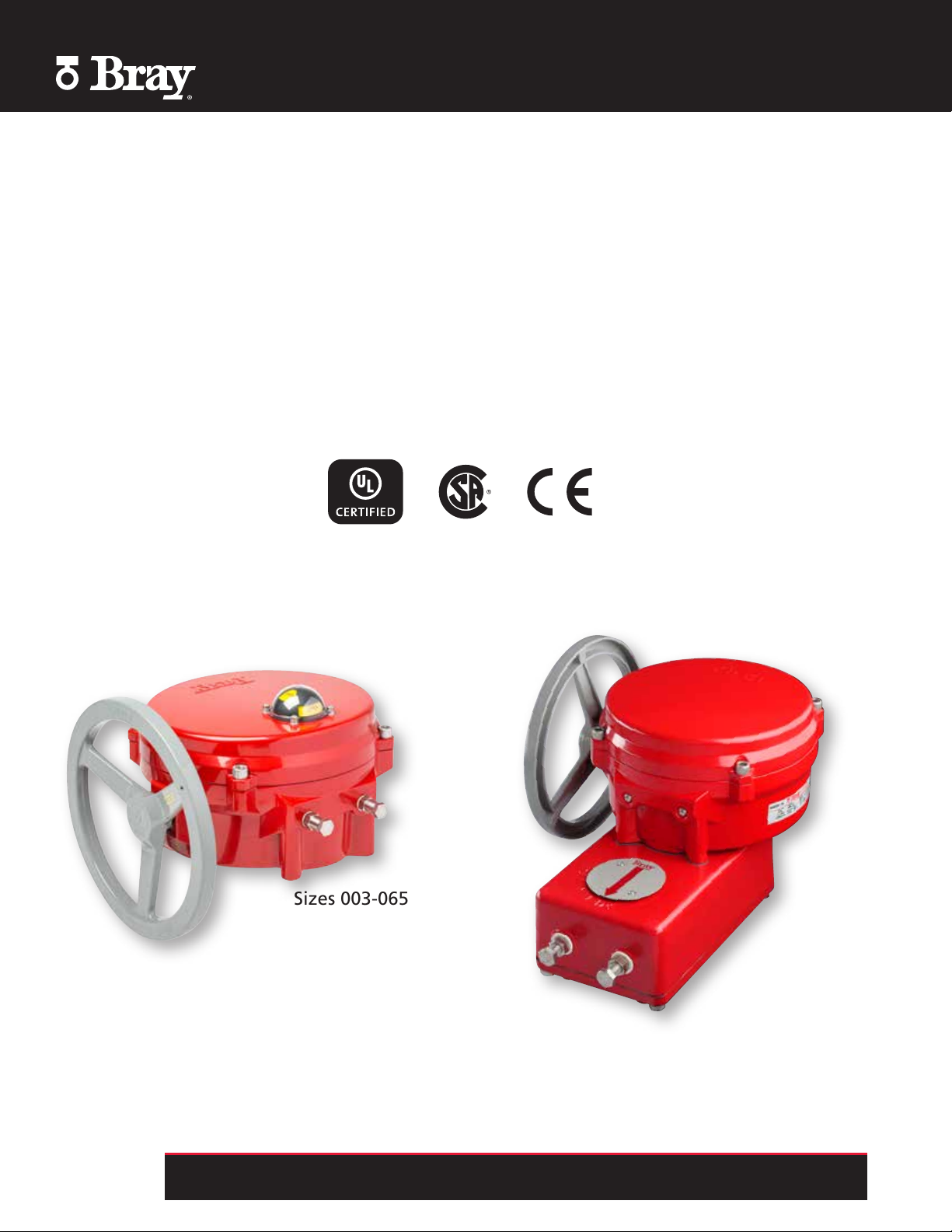
Sizes 003-065
Sizes 130-180
All information herein is proprietary, confidential, and may not be copied or reproduced without the expressed written consent of BRAY INTERNATIONAL, Inc.
2
The technical data herein is for general information only. Product suitability should be based solely upon customer’s detailed knowledge and experience with their application.
The right to change or modify product design or product without prior notice is reserved.
Page 3
SERIES 70 ELECTRIC ACTUATOR
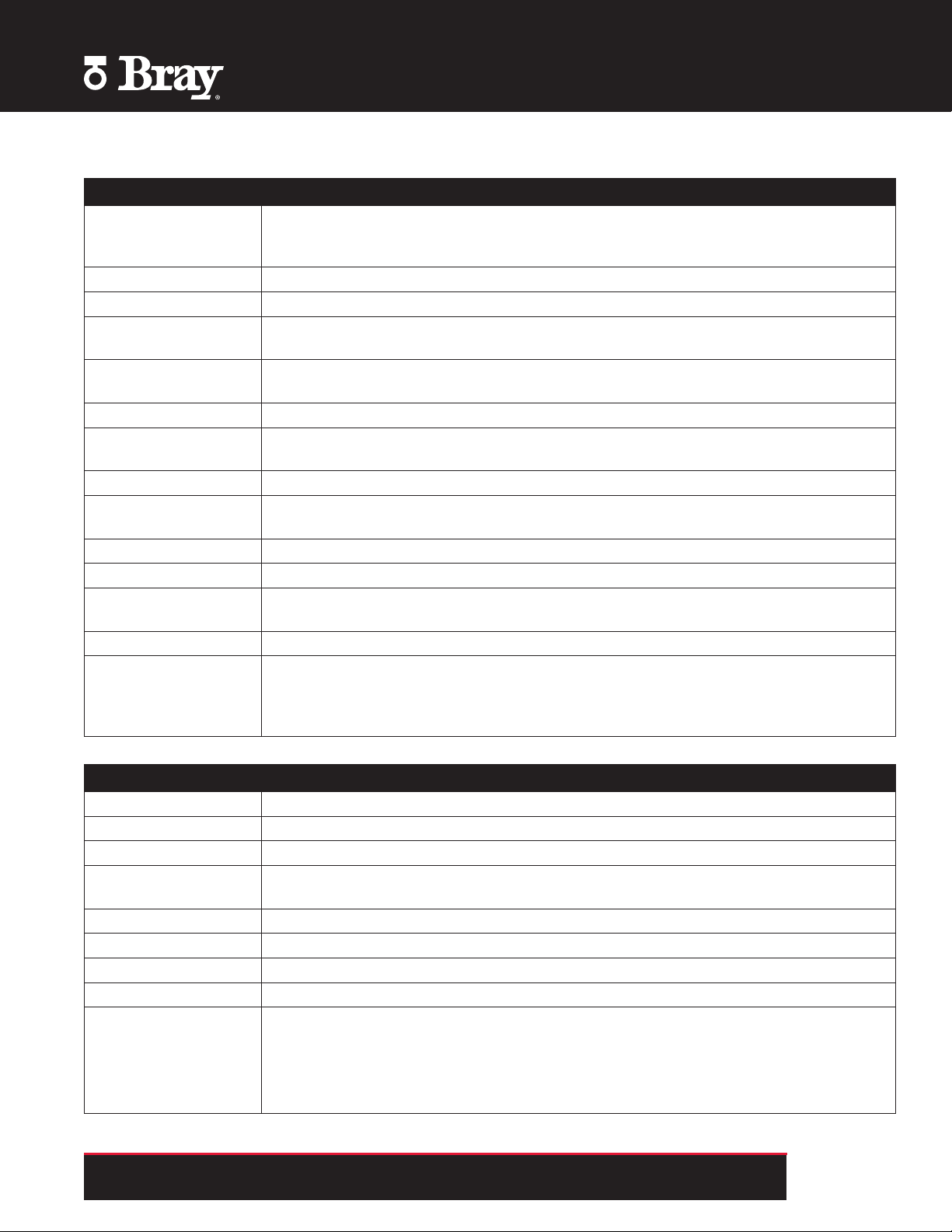
Specifications
CONSTRUCTION
Housing ASTM B85 pressure die cast aluminum
Polyester powder coated
Seacorr coated (optional)
Exposed Fasteners Stainless steel
Travel Stops Externally adjustable at both 0 and 90 degrees
Conduit Entries S70-003 to S70-006: 2 x 1/2” NPT or 2 x M20
S70-008 to S70-180: 2 x 3/4” NPT or 2 x M25
Worm Gearing Worm: Chromoly, self locking
Worm gear: Aluminum bronze
Spur Gearing AGMA class 9, nitride hardened alloy steel
Bearings Indicator shaft and motor gear: Permanently sealed ball bearing
Worm shaft: Sintered bronze bushing with heavy duty thrust bearing
Lubrication High temperature synthetic grease
Motor 120/220 VAC: Single phase, reversible, permanent split capacitor induction motor
24V: Permanent magnet-brush DC motor
Capacitor 110/220 VAC: Metalized polyester
Heater Optional, 5 watt PTC style
Terminal Strip Switch Plate: 12 - 22 AWG (2.0 - 0.65mm)
Servo: 14 - 24 AWG (1.63 - 0.51mm)
Torque Limiting Optional, open and close preset at factory
Limit Switches SPDT: 120VAC -10A-1/3 HP
220VAC -10A-1/2 HP
250VDC - 1/4A
12VDC - 2A
PERFORMANCE
Output Torque See Torque Chart
Voltages See Motor Chart
Ambient Temperature -20°F to 150°F (-29°C to 65°C)
Motor Insulation 120/ 220 VAC: Class F, 311°F (155°C) thermal trip at 275°F (135°C)
24V: Class B, slow blow fuse 5A@250VAC
Continuous Duty Will operate continuously at a max. ambient temperature of 104°F (40°C)
Intermittent Duty (25%): One motor-on period followed by three motor-off periods
Manual Operation Pull to engage, push to disengage
Enclosure Designed to meet NEMA Type 4, 4x and IP65 specifications
Certifications UL, CSA and CE approved (most models)
UL approved (USA & Canadian Std) for hazardous location
S70-708 to S70-720: 120VAC
Class I, DIV 1 & 2, Group C, D
Class II, DIV 1 & 2, Group E, F, G
All information herein is proprietary, confidential, and may not be copied or reproduced without the expressed written consent of BRAY INTERNATIONAL, Inc.
The technical data herein is for general information only. Product suitability should be based solely upon customer’s detailed knowledge and experience with their application.
The right to change or modify product design or product without prior notice is reserved.
3
Page 4

SERIES 70 ELECTRIC ACTUATOR
Battery Backup Unit (BBU) 24V Specifications
CONSTRUCTION AND PERFORMANCE
Housing ASTM B85 pressure die cast aluminum
Polyester powder coated
Seacorr coated (optional)
Exposed Fasteners Stainless steel
Batteries Two 12V 1.4AH sealed lead acid batteries wired in series
Battery Monitoring Local LED indicator and voltage free 2-wire normally open contact for remote monitoring
Battery Charging Automatic smart charge
Battery Conservation Shut-off batteries after one minute or when actuator stops
Operating Temperature -4ºF (-20ºC) to 122ºF (50ºC) LED light may not function below -20ºF (-29°C)
Power Protection Two 5 amp fuses, one for the external power output circuit and the other for the battery
output circuit
Current Draw @ 24 VAC BBU only maximum 10mA standby (0.25 VA)
Max. 420mA charging (10 VA)
Current Draw of
Actuator with BBU
Power Requirements 24-27VAC or 30-38VDC
Power Output BBU output with 24VAC supply is 30-38 VDC
600 lb-in - 1.9A (with load)
2,000 lb-in - 2.7A (with load)
5,000 lb-in - 4.1A (with load)
(the minimum voltage is required to provide proper battery charging)
Use dedicated Class 2 non-bonded transformer rated 100VA per BBU
On failure of AC supply, battery output is 24-25.5 VDC
BBU will provide fail open or fail close operation
BATTERY SPECIFICATIONS
Batteries Two 12 volt 1.4 ampere-hour (AH) rechargeable sealed lead acid battery wired in series
Features Valve regulated, spill proof construction allows safe operation in any position
Rugged impact resistant ABS case and cover (UL94-HB)
U.L. Recognized under file number MH 20845
Specifications Battery case: ABS plastic
Maximum discharge current (7 minutes): 4.2 amperes
Shelf Life (% of nominal capacity at 68ºF (20ºC)
1 month = 97%
3 months = 91%
6 months = 83%
Operating Temperature Charge: -4ºF to 122ºF (-20ºC to 50ºC)
Discharge: -40ºF to 140ºF (-40ºC to 60ºC)
The BBU should be powered up for a minimum of 12 hours
Although charging will not work at -4°F (-20°C), the batteries will still hold their charge for an extended period of time as described under
Shelf Life. See Bray Series 70 BBU Operation and Maintenance Manual for detailed information.
All information herein is proprietary, confidential, and may not be copied or reproduced without the expressed written consent of BRAY INTERNATIONAL, Inc.
4
The technical data herein is for general information only. Product suitability should be based solely upon customer’s detailed knowledge and experience with their application.
The right to change or modify product design or product without prior notice is reserved.
Page 5

Torque and Motor Data
SERIES 70 ELECTRIC ACTUATOR
S70-003 S70-006 S70-008
S70-708*
Torque
Actuator Weight
Approx.
MANUAL OVERRIDE
Handwheel Dia.
Gear Ratio 30:1 30:1 30:1 30:1 30:1 30:1 30:1 30:1 90:1 90:1
Rim Pull
* Hazardous Location Units
lb-in 300 600 800 1200 2000 3000 5000 6500 13000 18000
Nm 34 68 90 136 226 339 565 734 1469 2034
lbs 11 11 25 25 25 45 45 45 118 118
kg 5 5 11 11 11 20 20 20 54 54
in 3.5 3.5 8 8 8 12 12 12 12 12
mm 89 89 203 203 203 300 300 300 300 300
lbs 16 32 18 28 46 37 62 80 80 80
kg 7.2 14.5 8.2 12.7 20.8 16.8 28.1 36.3 36.3 36.3
S70-012
S70-712*
S70-020
S70-720*
S70-030 S70-050 S70-065 S70-130 S70-180
120VAC
Travel Time
90°
(Sec)
60 Hz 50 Hz FLA LRA FLA LRA FLA LRA FLA LRA FLA LRA FLA LRA FLA LRA FLA LRA FLA LRA FLA LRA
10 12 1.20 2.10 1.40 2.30
15 18 0.78 2.10 1.20 2.10 1.70 2.30
18 22 1.80 3.00 2.30 3.10
30 36 0.60 1.00 0.80 1.00 0.60 2.10 0.78 2.10 1.00 2.10 1.20 3.00 1.60 3.00 2.30 3.10
110 132 2.30 3.10 2.50 3.10
* Hazardous Location Units
S70-003 S70-006 S70-008
S70-708*
S70-012
S70-712*
S70-020
S70-720*
Current Draw in Amps
S70-030 S70-050 S70-065 S70-130 S70-180
220VAC
Travel Time
90°
(Sec)
60 Hz 50 Hz FLA LRA FLA LRA FLA LRA FLA LRA FLA LRA FLA LRA FLA LRA FLA LRA FLA LRA FLA LRA
10 12 0.50 0.76 0.60 0.81
15 18 0.38 0.90 0.50 0.76 0.55 0.90
18 22 0.78 1.40 1.10 1.40
30 36 0.60 0.75 0.65 0.75 0.38 0.90 0.45 0.90 0.50 0.81 0.75 1.2 0.90 1.40 1.10 1.40
110 132 1.30 2.70 1.50 2.70
FLA - Full Load Amperage
LRA - Locked Rotor Amperage
S70-003 S70-006 S70-008
S70-708
24VAC
Travel Time
90°
(Sec)
60 Hz 50 Hz FLA FLA FLA
60 72 1.80 2.00 4.00
For all other information such as dimensional drawings, wiring diagrams, and EDS files please visit bray.com or contact your local Bray representative.
S70-006 S70-020 S70-050
Current Draw in Amps
S70-012
S70-712
S70-020
S70-720
Current Draw in Amps
24VDC
Travel Time
90°
(Sec)
40 1.80
60 2.00 4.00
S70-006 S70-020 S70-050
Current Draw in Amps
FLA FLA FLA
S70-030 S70-050 S70-065 S70-130 S70-180
Travel Time - Motors
30, 40, 60, 110 second motors are continuous duty
10, 15, 18 second motors are intermittent duty
All information herein is proprietary, confidential, and may not be copied or reproduced without the expressed written consent of BRAY INTERNATIONAL, Inc.
The technical data herein is for general information only. Product suitability should be based solely upon customer’s detailed knowledge and experience with their application.
The right to change or modify product design or product without prior notice is reserved.
5
Page 6

SERIES 70 ELECTRIC ACTUATOR
Actuator Mounting
Imperial (in)
Actuator
Size
S70-003 F07 2.76 4 5/16 - 18 - - - - 0.75 0.51 1.75 -
S70-006 F07 2.76 4 5/16 - 18 - - - - 0.75 0.51 1.75 -
S70-008
S70-708
S70-012
S70-712
S70-020
S70-720
S70-030 F12 4.92 4 1/2 - 13 F16 6.50 4 3/4 - 10 1.97 - 2.60 2 x 7/16
S70-050 F12 4.92 4 1/2 - 13 F16 6.50 4 3/4 - 10 1.97 - 2.60 2 x 7/16
S70-065 F12 4.92 4 1/2 - 13 F16 6.50 4 3/4 - 10 1.97 - 2.60 2 x 7/16
S70-130 F12 4.92 4 1/2 - 13 F16 6.50 4 3/4 - 10 1.97 - 5.40 4 x 7/16
S70-130 F12 4.92 4 1/2 - 13 F16 6.50 4 3/4 - 10 2.50 - 5.40 4 x 5/8
S70-180 F12 4.92 4 1/2 - 13 F16 6.50 4 3/4 - 10 1.97 - 5.40 4 x 7/16
S70-180 F12 4.92 4 1/2 - 13 F16 6.50 4 3/4 - 10 2.50 - 5.40 4 x 5/8
F07 2.76 4 5/16 - 18 F12 4.92 4 1/2 - 13 1.18 0.87 2.20 -
F07 2.76 4 5/16 - 18 F12 4.92 4 1/2 - 13 1.18 0.87 2.20 -
F07 2.76 4 5/16 - 18 F12 4.92 4 1/2 - 13 1.18 0.87 2.20 -
Inner Bolt Circle Outer Bolt Circle Stem Hole
Bolt
Circle
No.
Holes
Bolt
Size
Bolt
Circle
No.
Holes
Bolt
Size
Dia.
Across
Flats
Depth Keyway Width
Metric (mm)
Actuator
Size
S70-003 F07 70 4 M8 x 1.25 - - - - 19 13 44.5 -
S70-006 F07 70 4 M8 x 1.25 - - - - 19 13 44.5 -
S70-008 F07 70 4 M8 x 1.25 F12 125 4 M12 x 1.25 30 22 55.9 -
S70-012 F07 70 4 M8 x 1.25 F12 125 4 M12 x 1.25 30 22 55.9 -
S70-020 F07 70 4 M8 x 1.25 F12 125 4 M12 x 1.25 30 22 55.9 -
S70-030 F12 125 4 M12 x 1.75 F16 165 4 M20 x 1.75 50.04 - 66 2 x 12.0
S70-050 F12 125 4 M12 x 1.75 F16 165 4 M20 x 1.75 50.04 - 66 2 x 12.0
S70-065 F12 125 4 M12 x 1.75 F16 165 4 M20 x 1.75 50.04 - 66 2 x 12.0
S70-130 F12 125 4 M12 x 1.75 F16 165 4 M20 x 1.75 50.04 - 137.2 4 x 12.0
S70-130 F12 125 4 M12 x 1.75 F16 165 4 M20 x 1.75 63.50 - 137.2 4 x 16.0
S70-180 F12 125 4 M12 x 1.75 F16 165 4 M20 x 1.75 50.04 - 137.2 4 x 12.0
S70-180 F12 125 4 M12 x 1.75 F16 165 4 M20 x 1.75 63.50 - 137.2 4 x 16.0
Inner Bolt Circle Outer Bolt Circle Stem Hole
Bolt
Circle
No.
Holes
Bolt
Size
Bolt
Circle
No.
Holes
Bolt
Size
Dia.
Across
Flats
Depth Keyway Width
All information herein is proprietary, confidential, and may not be copied or reproduced without the expressed written consent of BRAY INTERNATIONAL, Inc.
6
The technical data herein is for general information only. Product suitability should be based solely upon customer’s detailed knowledge and experience with their application.
The right to change or modify product design or product without prior notice is reserved.
Page 7

Standard Drawings
SERIES 70 ELECTRIC ACTUATOR
Standard Dimensional Drawings
Imperial Standard GA-17500
Metric Standard GA-17499
Imperial Hazardous Location ES11A-0526
Imperial 13,000-18,000 lb-in ES11A-0708
Metric 13,000-18,000 lb-in ES12A-0708
Standard Wiring Diagrams
120/220 VAC On/Off w/ IRB WD-000044
120/220 VAC Servo NXT WD-000338
120/220 VAC Servo Pro WD-000116
24 VAC On/Off w/Aux Switch - S70-003 to 006 WD-000276
24 VAC On/Off w/Aux Switch - S70-008 to 020 WD-000234
24 VAC On/Off w/Aux Switch - S70-030 to 065 WD-000111
24 VAC Servo Pro WD-000145
BBU 24V On/Off w/ Aux Switch - S70-003 to 006 WD-000285
BBU 24V On/Off w/ Aux Switch - S70-008 to 020 WD-000289
BBU 24V On/Off w/ Aux Switch - S70-030 to 065 WD-000270
BBU 24V Servo Pro w/ Aux Switch - S70-003 to 006 WD-000159
BBU 24V Servo Pro w/ Aux Switch - S70-008 to 065 WD-000266
All information herein is proprietary, confidential, and may not be copied or reproduced without the expressed written consent of BRAY INTERNATIONAL, Inc.
The technical data herein is for general information only. Product suitability should be based solely upon customer’s detailed knowledge and experience with their application.
The right to change or modify product design or product without prior notice is reserved.
7
Page 8

THE HIGH PERFORMANCE COMPANY
BRAY INTERNATIONAL
PRIMARY SALES AND SERVICE LOCATIONS
USA
Houston, Texas
AFRICA
Johannesburg
BENELUX
Heerhugowaard
BRAZIL
Paulinia, Sao Paulo
CANADA
Montreal
CHILE
Santiago
CHINA
Hangzhou, Zhejiang
COLOMBIA
Bogotá
FRANCE
Voiron
GERMANY
Krefeld
INDIA
Vadodara
ITALY
Milano
MEXICO
Zapopan, Jalisco
MIDDLE EAST
Dubai
PACIFIC
Melbourne, Australia
PERU
Lima
POLAND
O´swi¸ecim
RUSSIA
Moscow
SINGAPORE
Ubi Techpark
SOUTH KOREA
Seoul
SOUTHEAST ASIA
Malaysia
UNITED KINGDOM
Glasgow
FLOW-TEK RITE CORPORATION AMRESIST KUGELHAHN MÜLLER
USA
Houston, Texas
CANADA
Montreal
USA
Houston, Texas
GERMANY
Krefeld
BRAZIL
Paulinia, Sao Paulo VALVTRONIC BRAY/VAAS
CHINA
Hangzhou, Zhejiang
ARGENTINA
Buenos Aires
INDIA
Chennai
HEADQUARTERS
Bray International, Inc.
13333 Westland East Blvd.
Houston, Texas 77041
Tel: 281.894.5454
bray.com
All statements, technical information, and recommendations in this bulletin are for general use only. Consult
Bray representatives or factory for the specific requirements and material selection for your intended
application. The right to change or modify product design or product without prior notice is reserved.
Patents issued and applied for worldwide.
®
Bray
is a registered trademark of Bray International, Inc.
© 2017 Bray International. All rights reserved. TM-1055_Electric Actuator_09_2017
 Loading...