

Page 1
A Subsidiary of BRAY INTERNATIONAL, Inc.
INSTALLATION – MAINTENANCE MANUAL
MULTIPORT THREADED AND WELD END BALL VALVES
MPC, MPT, MPS, MPB 130/230/240
Installation and Maintenance Manual
®
Multiport Threaded and Weld End Ball Valves
Date: May 2011 / Page 1 of 3
USE:
Life of valves can be extended when it is maintained
under normal working conditions and in accordance
with pressure/temperature and corrosion data chart.
VALVE OPERATIONS:
The three way ball valve can be configured into several
options. Generally, flow pattern can be set with a quarter
(90 degree) turn or half (180 degree) turn. Please consult
our flow pattern chart for more information.
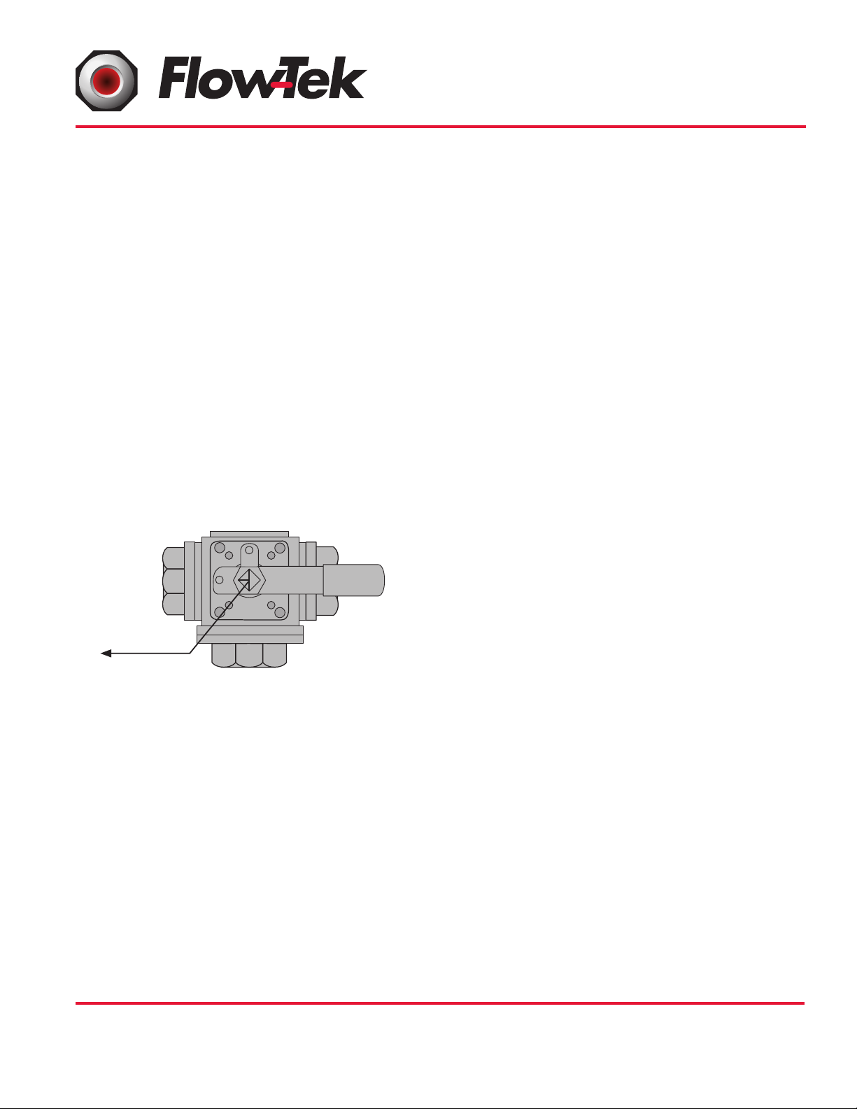
A. MANUAL OPERATION
Flow indicator shows the actual valve flow path. Illustration below shows the location of the flow indicator
on the valve stem. Turn the handle 90 degrees or 180
degrees in accordance to your set flow pattern.
flushed clean of dirt, burrs and welding residues
to prevent damage to the seats and ball surface.
• The pipeline must be free of tension.
INSTALLATION OF THREADED VALVES:
• Use conventional sealant, such as hemp core,
Teflon, etc. on the threads.
• Apply wrench on the hexagon end of the valve
only. Tightening by using the valve body or handle
can seriously damage the valve.
• For applications where screwed end valves are
back-welded on site, these valves must be dismantled according to instructions for weld end valves.
INSTALLATION OF WELD-END VALVES:
1. Prior to welding, end caps must be removed from the
body to prevent damage to the internal soft seals.
2. Weld end type valves already have the body bolts
loosen prior to shipment. Remove all the body bolts
(#19) and place them in a safe place.
Flow Direction
3. Remove each end caps (#2) from the body (#1)
and carefully remove the soft parts (seats #4 and
gaskets #5 from each of the end caps) and place
B. ACUTATOR OPERATION
Prior to actuator installation, please check the flow path
of the valve by observing the port openings. Mark this
opening on the ball valve prior to actuator installation
in order to get the correct flow orientation. After actuator installation, valve should be checked for valve stem
alignment. Angular or linear misalignment will result in
high operational torque and unnecessary wear on the
stem seal.
GENERAL INFORMATION FOR ON-SITE
INSTALLATION:
• The valve may be fitted in any position on the
them in a safe place.
4. Weld the pipe stub to each of the end caps. When
stub and the end cap has cooled down, clean both
end caps and stub body surface.
5. Replace the soft parts (seats #4 and gaskets #5)
into its original position. Replace all the bolts (#19)
and tighten slightly. This operation is very important
to keep body and end caps perfectly parallel, thus,
preventing distortion of the end caps.
6. Tighten body bolts evenly according to the body
bolt torque chart on next page.
7. Check the valve for proper operation.
pipeline.
• Before installing the valves, the pipes must be
FLOW-TEK, Inc. Tel: 832.912.2300
8323 N. Eldridge Pkwy #100 Fax: 832.912.2301
Houston, Texas 77041 www.flow-tek.com
© 2011 Flow-Tek, Inc.
Page 2

A Subsidiary of BRAY INTERNATIONAL, Inc.
Installation and Maintenance Manual
®
Multiport Threaded and Weld End Ball Valves
Date: May 2011 / Page 2 of 3
DISASSEMBLY AND CLEANING PROCEDURES:
Caution: Ball Valves can trap fluids in ball cavity
1. If the valve has been used to control hazardous media, it must be decontaminated before disassembly.
It is recommended that the following steps be taken
for safe removal and reassemble.
a. Relieve the line pressures.
b. Place the valve in all the available flow position
and flush the line to remove any hazardous
material from valve.
c. All persons involved in the removal and disas-
sembly of the valve should wear proper protective clothing, such as face shield, glove, and
apron, etc.
2. If valve is installed in the line, pipelines may have
to be cut to disassemble the valve. Inline weld
type valve can be disassembled without cutting
the pipelines.
PROCEDURES TO REPLACE REPAIR KIT:
1. Follow the direction on disassembly and cleaning
procedures.
2. Loosen each of body bolts (#19) and remove each
of end caps (#2) including the blank end cap (#22)
from the body (#1).
3. The seats (#4) are located inside end cap cavities.
Replace the seats (#4) and gaskets (#5) with new
ones. Place the end caps in a safe place.
4. To replace the stem components, the handle nut
(#18) must be loosen. To assist in loosening of the
handle nut, place a rod of diameter smaller than
the ball orifice into the ball orifice. Loosen and
remove the handle nut. Remove the handle (#16),
stop plate (#15), space washer (#14), and lock
saddle (#13). Larger valves size 2½” - 4”
only have handle T-Bar (not shown in the assembly
diagram).
(for ¼” - 2). For larger size valve 2½” - 4”,
remove the bonnet cap and the trunion ball can be
removed from the top of the valve body (not shown
in the assembly diagram). Clean all the removed
parts and place them in a safe place.
7. For valves ¼” - 2” size, push the stem (#6)
downward. It should come out through the center
body cavity. Remove the stem packing (#9), o-ring
(#8), and thrust washer (#7). Clean the stem and
replace with new stem packing, o-ring, and thrust
washer. For larger size ball valve 2½” - 2”,
replace with new o-ring, stem packing and bonnet
gasket (not shown in the assembly diagram).
8. Replace the stem (#6), gland (#10), belleville
washers (#11) and the stem nut. For larger
size valve 2½” - 4”, replace the trunion ball
and the bonnet cap
9. Tighten the stem nut according to the stem nut
torque chart on next page. For larger size
valve 2½” - 4”, tighten the circular gland until
it bottoms out.
10. Replace the lock saddle (#13), space washer
(#14), stop plate (#15), handle (#16), and handle
nut (#18). For larger size valve 2½” - 4”,
replace the handle t-bar and the lever (not shown
in the assembly diagram).
11. Replace the end caps and tighten the body bolts
evenly according to the body bolt torque chart on
next page. For large size valve 2½” - 4”,
also tighten the bonnet cap according to the body
bolt torque chart.
12. Check the valve for proper operation.
5. Loosen and remove the stem nut (#12), belleville
washer (#11), and gland. Larger valves size
2½” - 4” have gland, belleville washer, and
gland washer (not shown in the assembly diagram).
6. Remove the rod and the ball should slight out from
the center of ball valve body with a gentle push
FLOW-TEK, Inc. Tel: 832.912.2300
8323 N. Eldridge Pkwy #100 Fax: 832.912.2301
Houston, Texas 77041 www.flow-tek.com
© 2011 Flow-Tek, Inc.
Page 3

A Subsidiary of BRAY INTERNATIONAL, Inc.
Installation and Maintenance Manual
®
Multiport Threaded and Weld End Ball Valves
Date: May 2011 / Page 3 of 3
ASSEMBLY DIAGRAM
22
1
2
5
16
17
15
14
13
12
11
10
9
8
7
6
18
Regular Threaded
Female End Cap
19
20
5
2
1
No. Part Name Material
1 Body ASTM A351 Gr.
2 End Cap ASTM A351 Gr.
3 Ball SS 316
4 Seat TFM 1600
5 Gasket TFM 1600
6 Stem SS 316
7 Thrust Washer TFM 1600
8 O-Ring Viton
9 Stem Packing TFM 1600
22
10 Gland SS 304
11 Belleville Washer SS 301
12 Stem Nut SS 304
13 Lock Saddle SS 304
14 Space Washer SS 304
15 Stop Plate SS 304
16 Handle SS 304
Inline Weld Type
End Cap
22
1
21
4
5
2
3
5
2
1
22
Regular Weld Type
End Cap
17 Handle Sleeve Vinyl
18 Handle Nut SS 304
19 Body Bolt SS 304
20 Pin Insert SS 304
21 Stop Pin SS 304
22 Blank End ASTM A351 Gr.
23 Anti-Static Device SS 316
24 End Cap (Inner) ASTM A351 Gr.
25 ACP Gasket (Inner) TFM 1600
TORQUE DATA
The body bolts of the valve should be tightened evenly. Tighten one-side snugly, then
the one diagonally across. Repeat for the other bolts, bringing them all down tightly
in sequence to the torque shown below.
CF8M
CF8M
CF8M
CF8M
Body Bolt Torque Chart Stem Nut Torque Chart
Size
Torque
(In-Lb)
Bolt Size Size
1/4” 106 1/4” - 20UNC 1/4” 71 M12x1.75
3/8” 106 1/4” - 20UNC 3/8” 71 M12x1.75
1/2” 150 5/16” - 18UNC 1/2” 71 M12x1.75
3/4” 150 5/16” - 18UNC 3/4” 106 M14x2.0
1” 150 5/16” - 18UNC 1” 106 M14x2.0
1 1/4” 195 3/8” - 16UNC 1 1/4” 133 M18x2.5
1 1/2” 195 3/8” - 16UNC 1 1/2” 133 M18x2.5
2” 354 1/2” - 13UNC 2” 168 M22x2.5
2 1/2” 354 1/2” - 13UNC 2 1/2” N/A N/A
3” 354 1/2” - 13UNC 3” N/A N/A
4” 664 5/8” - 11UNC 4” N/A N/A
FLOW-TEK, Inc. Tel: 832.912.2300
8323 N. Eldridge Pkwy #100 Fax: 832.912.2301
Houston, Texas 77041 www.flow-tek.com
Torque
(In-Lb)
Nut Size
© 2011 Flow-Tek, Inc.
 Loading...