

Page 1
SERIES 6A
ELECTROPNEUMATIC POSITIONER
QUICK START GUIDE
This document is not comprehensive, and is intended to help first time users become familiar with
the Bray S6A Electropneumatic Positioner. For more detailed information the Installation, Operation
and Maintenance Manual is available on the Bray website.
Page 2
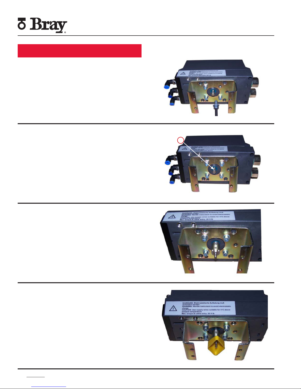
Mounting and Setup
Step 1: Place the mounting bracket on the
underside of the positioner. Tighten the
mounting bolts and lock washers.
Step 2: Position the output shaft of the
positioner so that the flat (1) portion is facing
upwards.
Series 6A Quick Start Guide
Installation, Operation and Maintenance Manual
1
Step 3: Insert the coupler over the output
shaft. Ensure proper alignment of the coupler’s
set screw with the flat side of the shaft before
tightening the set screw.
Step 4: Position the yellow indicator on the
base of the coupler.
BRAY.COM
2
|
Page 3
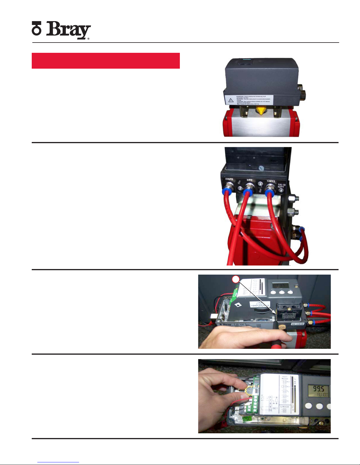
Mounting and Setup
Step 5: Position the positioner on the actuator
and tighten the mounting screws.
Step 6: Insert the pneumatic fittings on the
positioner and actuator before inserting tubing
into the outputs of the positioner to the inputs
of the actuator.
Series 6A Quick Start Guide
Installation, Operation and Maintenance Manual
Note: Supply air will be routed to Y1 in the
event of a signal loss (fail condition.)
• Single acting actuators release air from Y1
upon loss of signal.
• For double-acting actuators, make sure Y1
is connected to the desired port for fail
position.
Step 7: Position the yellow ‘Transmission Ratio
Selector’ tab (2) in the 90° position by pushing
it away from the labeled side of the device.
2
Step 8: Adjust the yellow clutch wheel on the
underside of the terminals using a 4 mm wide
screwdriver to the 90° position.
SERIES 6A QUICK START GUIDE
|
3
Page 4

Calibration
Step 1: Power on the unit with a 4 to 20 mA
signal.
Note: Make sure signal does not order turn-off
during calibration process.
Step 2: Press the Menu Button
for >5 seconds to enter into Configuration
mode.
Series 6A Quick Start Guide
Installation, Operation and Maintenance Manual
Step 3: Once in Configuration mode parameter
1 is displayed in the bottom left hand corner of
the positioner screen. Parameter 1 allows the
user to select the type of actuator being paired
with the device.
Step 4: Use the Up Button
the available options (in ascending order) until
you reach “turn”. This option is for quarter
turn actuators.
Note: To scroll through parameters in
descending order, hold down the
Menu Button while using the Down
Button
until you find “turn”.
-
to scroll through the parameters
+
to scroll through
BRAY.COM
4
|
Page 5

Calibration
Step 5: Press the Menu Button once to
reach parameter 2. Select 90°.
Step 6: Press the Menu Button to scroll to
parameter 4.
Series 6A Quick Start Guide
Installation, Operation and Maintenance Manual
Note: Parameter 3 is skipped for quarter-turn
actuators.
Step 7: Hold down the Up Button
calibration begins (>5 seconds), then release.
The device will now progress through 5
“RUNS”, completing a series of checks. For
more information on the calibration, please
refer to the product manual.
Note: The calibration routine can take up to 15
minutes.
+
until
Note: If an error is displayed on your positioner
during Run 2, the lower tolerance (down
tolerance) of the adjustment wheel has been
exceeded. (If no errors are displayed, skip
ahead to step 8.)
SERIES 6A QUICK START GUIDE
|
5
Page 6

Calibration
Adjust the gray friction clutch adjustment
wheel until the screen displays a 6 in the top
right hand corner.
If the clutch wheel is difficult to turn, ensure
that:
a. The yellow locking wheel under the friction
clutch adjustment wheel is not locked (rotate
right)
b. The friction clutch adjustment wheel is not
near the end of travel at either the high or
low end (If so, rotate in the opposite direction
to allow enough rotation to complete a
successful calibration).
Series 6A Quick Start Guide
Installation, Operation and Maintenance Manual
Once the down tolerance error has been
corrected, the middle character of the message
line will change to an ‘O’.
To continue calibration, press the
Up Button
+
once and release.
Step 8: Upon successful completion of
calibration, the status line will display “FINISH”.
Press the Menu Button once to exit.
BRAY.COM
6
|
Page 7

Calibration
Step 9: Press the Menu Button for 5
seconds. The device will now be in ‘MANUAL’
mode.
Series 6A Quick Start Guide
Installation, Operation and Maintenance Manual
Step 10: Use the- or
close or open the valve to ensure that the
desired travel limits are being attained.
Step 11: Toggle between Manual (“MAN”)
and ‘AUTO’ mode by pressing the
Menu Button .
+
buttons to manually
Step 12: While in ‘AUTO’ mode, test the
responsiveness of the device by varying the
command signal from 4 mA to 20 mA.
SERIES 6A QUICK START GUIDE
|
7
Page 8

Series 6A Quick Start Guide
Installation, Operation and Maintenance Manual
Calibration
Step 13: Upon completion of calibration,
insert a 4 mm wide screwdriver into the slot
located under the adjustment wheel and turn
the wheel left until you can feel that it clicks
in. This helps prevent the clutch wheel from
slipping during actuation.
To optimize performance, the following measures can be applied if the positioner is too
responsive and does not reach end of travel smoothly.
Step 14: While in configuration mode, scroll to
parameter 34 (DEBA).
Step 15: Increase the deadband to
yield the desired responsiveness by
pressing the Up Button.
(Default is 0.1%; Bray recommended
value is 1 to 2%).
+
BRAY.COM
8
|
Page 9

Positioner Optimization
This is an example of screen with increased
deadband responsiveness.
Step 16: Use the Menu Button to scroll to
parameter 39 (YCLS). This setting allows users
to assign a position where the 6A will default
to full open or close. Select ‘uP do’ by pressing
the Up Button.
uP – Only Upper Limit (Full Open)
do – Only Lower limit (Tight Close)
uP do – Upper and Lower limits set
+
Series 6A Quick Start Guide
Installation, Operation and Maintenance Manual
Step 17: Use the Menu Button to scroll
to parameter 40 (YCDO, tight close).
Step 18: Change the parameter value to the
desired lower limit for tight closing.
Example: If the positioner is at 10% or lower,
the actuator automatically goes to full close.
SERIES 6A QUICK START GUIDE
|
9
Page 10

Positioner Optimization
Step 19: Use the Menu Button to scroll
to parameter 41 (YCUP, full open).
Step 20: Change the parameter to the desired
upper limit for full open.
Series 6A Quick Start Guide
Installation, Operation and Maintenance Manual
Example: If the positioner is at 85% or higher,
the actuator provides full force open.
Step 21: Exit Configuration mode by pressing
the Menu Button for >5 seconds. The
device will be in Manual Mode (“MAN’).
Press the Menu Button once to leave the
positioner in AUTO mode.
HEADQUARTERS
Bray International, Inc.
13333 Westland East Blvd.
Houston, Texas 77041
Tel: 281.894.5454
bray.com
All statements, technical information, and recommendations in this bulletin are for general use only. Consult
Bray representatives or factory for the specific requirements and material selection for your intended application.
The right to change or modify product design or product without prior notice is reserved. Patents issued and
applied for worldwide.
Bray® is a registered trademark of Bray International, Inc.
© 2018 Bray International. All rights reserved. OM-6A-QuickStart_11_2018
 Loading...