

Page 1
SERIES 92/93
PNEUMATIC ACTUATOR
OPERATION AND MAINTENANCE MANUAL
Page 2

Ta b l e o f Co n T e n T s
Sa f e t y In f o r m a t I o n - De f I n I t I o n o f te r m S ............................................................................................. 1
De S c r I p t I o n o f op e r a t I o n .......................................................................................................................... 2
p e r a t I n g me D I u m ................................................................................................................................................. 2
o
n S t a l l a t I o n ........................................................................................................................................................... 2
I
o u n t I n g ac t u a t o r t o t h e Va l V e ................................................................................................................ 4
m
e t t I n g t h e tr a V e l St o p S .............................................................................................................................. 4
S
a I n t e n a n c e .......................................................................................................................................................... 5
m
r o u b l e S h o o t I n g .................................................................................................................................................... 6
t
S S e m b l y ................................................................................................................................................................ 6
a
I S a S S e m b l y ............................................................................................................................................................ 7
D
D D I n g Sp r I n g ca r t r I D g e S ..................................................................................................................................... 8
a
p r I n g ca r t r I D g e po S I t I o n Il l u S t r a t I o n ....................................................................................................... 8
S
e m o V I n g Sp r I n g ca r t r I D g e S ........................................................................................................................ 9
r
e n e r a l pn e u m a t I c Sy S t e m re c o m m e n D a t I o n S .................................................................................................... 10
g
I m e n S I o n a l Da t a ................................................................................................................................................. 10
D
e r I e S 92/93 pa r t S DI a g r a m ................................................................................................................................. 11
S
Page 3
Operations and Maintenance Instructions
!
!
!
sa f e T y In f o r m a T I o n - De f I n I T I o n o f Te r m s
WARNING indicates a potentially hazardous situation which, if not avoided, could
result in death or serious injury.
CAUTION indicates a potentially hazardous situation which, if not avoided, may
result in minor or moderate injury.
NOTICE used without the safety alert symbol indicates a potential situation which,
if not avoided, may result in an undesirable result or state, including
property damage.
Series 92-93 Pneumatic Actuator
Hazard-free use
This device left the factory in proper condition to
be safely installed and operated in a hazard-free
manner. The notes and warnings in this document
must be observed by the user if this safe condition
is to be maintained and hazard-free operation of
the device assured.
Take all necessary precautions to prevent damage
to the actuator due to rough handling, impact, or
improper storage. Do not use abrasive compounds
to clean the actuator, or scrape metal surfaces with
any objects.
The control systems in which the actuator is installed
must have proper safeguards to prevent injury to
personnel, or damage to equipment, should failure
of system components occur.
Qualified Personnel
A qualied person in terms of this document is
one who is familiar with the installation, commissioning and operation of the device and who has
appropriate qualications, such as:
Is trained in the operation and maintenance of •
pneumatic equipment and systems in accordance with established safety practices
Is trained or authorized to energize, de-energize, •
ground, tag and lock electrical and pneumatic
circuits and equipment in accordance with
established safety practices
Is trained in the proper use and care of personal •
protective equipment (PPE) in accordance with
established safety practices
Is trained in rst aid•
In cases where the device is installed in a •
potentially explosive (hazardous) location –
is trained in the operation, commissioning,
operation and maintenance of equipment in
hazardous locations
WARNING
The actuator must only be installed, commissioned,
operated and repaired by qualied personnel.
The device generates large mechanical force when
pressurized with air, and/or powered by springs.
The actuator stores a large amount of energy when
pressurized with air, and/or when the springs are
compressed.
To prevent injury, installation, commissioning,
operation and maintenance must be carried out
under strict observation of the safety regulations.
Reference is specically made here to observe the
applicable safety regulations for actuators installed
in potentially explosive (hazardous) locations.
All information herein is proprietary and condential and may not be copied or reproduced without the expressed written consent of BRAY INTERNATIONAL, Inc.
The technical data herein is for general information only. Product suitability should be based solely upon customer’s detailed knowledge and experience with their application.
1
Page 4

Series 92-93 Pneumatic Actuator
Operations and Maintenance Instructions
Correct and safe operation of this actuator is dependent upon proper transport, storage and installation
in addition to proper operation and maintenance.
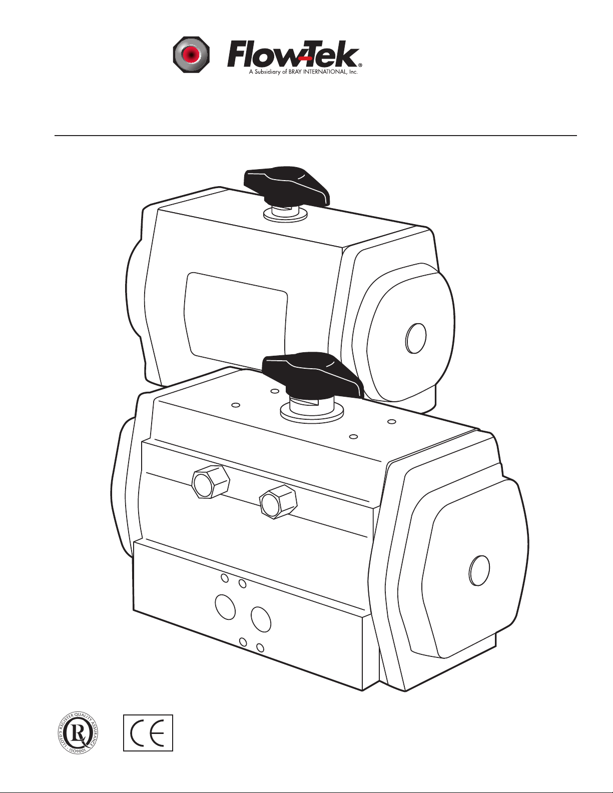
Description of Operation
The Flow-Tek Series 92/93 Pneumatic Actuators
feature a double piston, rack and pinion mechanism
designed to automate quarter-turn valves. In the
Series 92 Double-Acting Actuator, pressure introduced through Port A (the left port when facing
the ports) forces the pistons away from each other
and causes the pinion to rotate in a counterclockwise direction. Pressure introduced through Port
B (the right port when facing the ports) is directed
through an internal passage to the opposite side
of the pistons, which forces the pistons together
and rotates the pinion in a clockwise direction.
Normally, the clockwise rotation (pistons moving
together) closes the attached valve, and the counterclockwise rotation (pistons moving apart) opens
the attached valve.
In the Series 93 Spring-Return Actuators, spring cartridges have been added to push the pistons together
by spring force in the event the compressed air pressure is lost. This spring force normally closes the
attached valve. However, in the event that the valve
is required to open under spring force, refer to the fail
open portion of the Installation section below.
Operating Medium
NOTICE
Operating Temperature
NOTICE
The recommended operating temperature range
is -15°F to 200°F (-25°C to 95°C). Below 32°F
(0°C) care must be taken to prevent condensed
moisture from freezing in the air supply lines.
Consider the use of an air dryer if the device is
installed in a cold location. The air dryer must
be capable of lowering the dew point of the air to
a temperature 36°F (20 °C) lower than that of the
surrounding environment. The air dryer must be
properly maintained and kept in operation.
Installation
Flow-Tek Series 92/93 Actuators are designed
to Flow-Tek Valves through a series of heavy
duty brackets and couplers. Before the actuator
is mounted on a valve, it is a good practice to
lubricate the output bore of the actuator with thick
grease. The grease will make it easier to remove
the actuator from the mounting coupler, even after
years of service.
Normally, the actuator is mounted with its long side
parallel to the pipeline. A double acting actuator will
normally rotate the valve stem clockwise to close,
and counterclockwise to open. Spring return actuators will normally rotate the valve stem clockwise to
close with the spring stroke, and counterclockwise
to open with the air stroke. The normal operation
of the spring cartridges is therefore fail closed.
The recommended operating medium is clean, dry
industrial compressed air, 40 - 140 psig (3 - 10
bar.) An air line lubricator is suggested for fast
cycling applications, i.e. more than 10 cycles per
minute. Other media such as hydraulic oil, water,
or certain other inert gases may also be used in
some instances, but the factory should be consulted
for specic applications.
2
All information herein is proprietary and condential and may not be copied or reproduced without the expressed written consent of BRAY INTERNATIONAL, Inc.
The technical data herein is for general information only. Product suitability should be based solely upon customer’s detailed knowledge and experience with their application.
Direction of operation may be changed to fail open
by any one of several different methods. Refer to
the Assembly Instructions and Exploded View in
Figure 3 on page 12 for more details.
Page 5

Fail Open Method 1 – Mounting the Actuator
!
!
Perpendicular to the Pipeline
Series 92-93 Pneumatic Actuator
Operations and Maintenance Instructions
WARNING
NOTICE
Fail Open Method 1 – Mounting the Actuator
Perpendicular to the Pipeline – works only with
valves that allow the ball to be swung through
the seat.
Turn the actuator so the long side is perpendicular
to the pipeline. This will allow the spring cartridges
to rotate the valve stem clockwise to open, and the
air stroke to rotate the valve stem counterclockwise
to close. This is the easiest method if there is sufcient room to mount the actuator.
Fail Open Method 2 – Rotating the Pinion
NOTICE
Fail Open Method 2 – Rotating the Pinion - works
only with valves that allow the ball to be swung
through the seat.
Some actuators may have spring cartridges installed.
Before disassembly, all spring cartridges must be
placed into the relaxed (fully extended) position.
All compressed air must be removed from inside
the actuator (See warning above) and the actuator
pinion must be allowed to rotate so the springs may
be relaxed. Care must be taken to verify that any
device connected to the actuator, such as a valve
mounted underneath, is not preventing the movement of the springs to the relaxed position.
Remove the end caps, spring cartridges and pistons
from the actuator. Remove the pinion, rotate it
90°, and reinstall the pinion in the actuator. This
will also allow the spring cartridges to rotate the
valve stem clockwise to open, and the air stroke to
rotate the valve stem counter-clockwise to close.
This is the second easiest method, and allows the
actuator to be mounted with its long side parallel
to the pipeline.
Fail Open Method 3 – Reversing the Pistons
See Assembly (Page 6) for detailed instructions on
reinstalling the travel stop cam on the pinion.
Fail Open Method 3 – Reversing the Pistons –
works for all valves, where the ball may only turn
WARNING
Before disassembly of the actuator, the pneumatic
air supply must be completely disconnected from
the actuator, and all compressed air stored within
the actuator must be released. Auxiliary devices
connected to the actuator, such as tubing, ball
valves, solenoid air valves, valve positioners, etc.
can block the release of air from within the actuator.
Do not rely upon the features or controls of any
auxiliary device to release the air from inside the
actuator and render it safe for disassembly.
All information herein is proprietary and condential and may not be copied or reproduced without the expressed written consent of BRAY INTERNATIONAL, Inc.
The technical data herein is for general information only. Product suitability should be based solely upon customer’s detailed knowledge and experience with their application.
clockwise to close.
See Assembly (Page 6) for detailed instructions on
reinstalling the travel stop cam on the pinion.
Remove the end caps, spring cartridges and pistons
from the actuator. Rotate the pistons so that the racks
turn the pinion counterclockwise as the pistons move
toward each other. (With the air input ports of the
actuator body facing you, the left hand piston rack
should be on the side with the air ports.) This is the
third easiest method, and allows the actuator to be
mounted with its long side parallel to the pipeline,
and clockwise to close rotation to be maintained.
NOTICE
3
Page 6

Mounting the Actuator to the Valve
5°
5°
!
The actuator is attached to the valve by means of
the mounting kit. Thread the studs into the proper
holes in the actuator, before installing the actuator on the valve. The studs should be snug in the
bottom of the tapped holes; there is no need to
torque them. Install the actuator on the valve or
mounting bracket making sure that the base of the
actuator ts at against the mounting ange. Use
the nuts and washers from the kit to complete the
installation. Torque the nuts in a diagonal pattern
to assure equal loading of the studs.
Series 92-93 Pneumatic Actuator
Operations and Maintenance Instructions
WARNING
Before setting the travel stops, the pneumatic air
supply must be completely disconnected from the
actuator, and all compressed air stored within the
actuator must be released. Auxiliary devices connected to the actuator, such as tubing, ball valves,
solenoid air valves, valve positioners, etc. can
block the release of air from within the actuator.
Do not rely upon the features or controls of any
auxiliary device to release the air from inside the
actuator and render it safe for disassembly.
Setting the Travel Stops
The nal step in the installation process is to check
the travel stop settings. The travel stops are set for
90° of travel at the factory; however, each installation
is different so they should be checked before putting
the valve in service. The actuators are designed
with a nominal 5° over or under travel at each end
of rotation. A screwdriver, an open end or box end
wrench and a hex wrench, all of the appropriate size,
are the only tools required to make the necessary
adjustments. Refer to Figure 1 below.
Remove the black position pointer to expose the
wrench ats on the top of the pinion.
Rotate the valve to the desired position using a
wrench on the pinion.
Loosen the lock nut on the travel stop screw. It is
not necessary to remove the nut completely. Using the hex wrench, turn the screw in or out until
the desired travel stop position is reached. While
holding the screw with the hex wrench, tighten the
lock nut with the wrench.
Replace the position indicator making certain the
pointer is aligned with the position of the valve,
open or closed.
Replace the position indicator making certain the
pointer is aligned with the position of the valve,
open or closed.
Figure 1
4
All information herein is proprietary and condential and may not be copied or reproduced without the expressed written consent of BRAY INTERNATIONAL, Inc.
The technical data herein is for general information only. Product suitability should be based solely upon customer’s detailed knowledge and experience with their application.
Page 7

Some valves or operating conditions require that
the actuator have more that 5° of travel adjustment.
For these conditions, the Series 92/93 actuator can
be tted with extended travel stops in the end caps.
(See Pg. 10 for instructions on nding dimensional
data) Consult the Flow-Tek distributor in your area
for this option.
Spring return actuators may be operated with only
one air supply connected to Port A, since the spring
cartridges will move the pistons when the air pressure in removed. This operation, however, will
draw the surrounding atmosphere into the spring
chambers through Port B.
NOTICE
Series 92-93 Pneumatic Actuator
Operations and Maintenance Instructions
NOTICE
To lengthen service life, it is strongly recommended
that an adequately sized lter with a 40 micron
(or ne) element be installed adjacent to the inlet
of the directional control (solenoid air) valve. Air
lubricators are recommended for rapid cycling
applications (10 cycles or more per minute.)
Routine maintenance of Series 92/93 actuators
consists primarily of maintaining the air supply
system by changing lter elements before they
start by-passing, adding oil to lubricators before
they run dry, and preventing water from entering
the air lines.
To prevent contamination from entering the spring
chamber, actuators congured to operate with
only one air supply connected to Port A should be
equipped with a 40 micron (or ner) lter element
installed in Port B.
Even better service may be obtained on spring return
actuators by installing a four-way solenoid, covering both Port A and Port B. A four-way solenoid
will ll the spring chambers with compressed air
from the plant air supply with each stroke. The
plant air supply is often cleaner than the surrounding atmosphere, especially in heavy industrial or
chemical areas.
Maintenance
The rugged components and factory lubrication
combine to ensure a long and trouble-free service
life for Series 92/93 actuators. Dirt, rust and water
are the most common causes for shortened service
life, and they typically enter the actuator through
the air supply line.
The second most common cause of shortened service
life is misalignment between the valve and the actuator. This can cause premature failure due to excessive
side loads on the bearings and gear teeth.
NOTICE
To lengthen service life, the mechanical connec-
tion between the actuator and the valve should be
veried to be properly aligned and free to rotate
throughout the full range of valve travel.
All information herein is proprietary and condential and may not be copied or reproduced without the expressed written consent of BRAY INTERNATIONAL, Inc.
The technical data herein is for general information only. Product suitability should be based solely upon customer’s detailed knowledge and experience with their application.
5
Page 8

Series 92-93 Pneumatic Actuator
Operations and Maintenance Instructions
Troubleshooting
Table 1 shows several common symptoms and their remedies.
Symptom Probable Cause Check Remedy
Loss of Power Low air supply pressure, or
damaged O-rings
Binding between
Misalignment of coupling Alignment Realign coupling
valve and actuator
Valve “pops” out of
seat and slams open
Valve torque too high,
actuator sized too small, or
insufcient air supply ow
Assembly
To identify component names and shapes, refer
to the Exploded View of the actuator shown on
Figure 4, pg. 11. The numbers in parentheses ( ) refer
to the numbered bubbles in Figure 3. Easiest assembly will result from lubricating all bearings and seals
as they are installed. The lubricant should be a high
pressure or extreme pressure petroleum grease with a
lithium based thickener which meets the NLGI grade
2. Grease which meets this specication should be
available from any automotive supply store.
Pinion (3) - Install bearing rings (6 & 7) and o-rings
(18 & 19) in their appropriate grooves. Insert the
pinion through the large hole in the center of the
body (1). With the pinion part of the way into the
body, slide the cam (23) over the pinion being careful
to align the punch mark on the cam with the punch
mark(s) on the pinion. For normal installation and
rotation (Fail Close), align the single marks. For
Fail Open operation described in Method 2 above,
align the single mark on the cam with the two marks
on the pinion. For Fail Open operation described in
Method 3 above, align the single marks. Next, install
the spacer (24) above the cam. Then insert the pinion
through the hole at the top of the body and secure it
with the washer (9) and retaining ring (8).
Air supply pressure at
actuator, leakage across
O-rings
Valve torque, actuator
sizing calculations, size
of air supply lines and/
or solenoid valve
Boost air supply pressure, repair air supply line
leaks, replace O-rings
Repair valve, use proper
size actuator, use larger
air supply lines and/or solenoid valve with higher
ow
Travel Stop Screws (13) - Slip the o-ring (14) over
the at end of the screw until it is 5-7 threads from
the end. Thread the screw into the hole in the body,
at end rst. Repeat these steps for the second
screw. Thread the lock nuts (12) onto the screws
and tighten the nuts against the body. This will seal
the threads for testing. It is not necessary to set the
travel stops at this time, as they may have to be reset
when the actuator is installed on the valve.
Pistons (2) - Install the bearing pad (10) on the
back of the rack and the o-ring (16) and guide ring
(11) in their appropriate piston grooves. The o-ring
goes in the groove nearest the rack. With the ports
on the actuator body toward you, turn the pinion
so that the slot is approximately 45° to the right of
perpendicular with the long side of the body. Grasp
the pistons in the spring pockets so that the piston
in the right hand has the bearing pad toward you
and the piston in the left hand has the bearing pad
away from you. Slide the pistons into the body so
that they both engage the teeth on the pinion at the
same time. Apply enough steady force to compress
the o-ring into the body bore. At this point, you may
continue pushing or use a wrench on the top of the
pinion to pull the pistons into the body.
6
All information herein is proprietary and condential and may not be copied or reproduced without the expressed written consent of BRAY INTERNATIONAL, Inc.
The technical data herein is for general information only. Product suitability should be based solely upon customer’s detailed knowledge and experience with their application.
Page 9

NOTICE
!
!
Three important parameters must be veried before
assembly may be continued.
The pinion must turn clockwise as the pistons 1.
moved toward the center of the body.
The 4 mm slot in the top of the pinion must be 2.
within a few degrees of perpendicular to the long
side of the body.
The piston faces must both be the same distance 3.
from the end of the body.
If all three parameters above have been veried, the end
caps may be installed.
If any parameter above is not veried, use a wrench on
the pinion to drive the pistons out of the body and repeat
the insertion process. It is not necessary to remove the
pistons from the body unless the answer to the rst
question is no. It is only necessary to disengage the
piston rack from the pinion.
NOTICE
The assembly procedure described here is the standard
Fail Close method. For Fail Open actuators, refer to
Method 2 or Method 3 above.
Series 92-93 Pneumatic Actuator
Operations and Maintenance Instructions
Final Assembly and Testing
CAUTION
Do not connect a compressed air supply to the actuator
that exceeds the pressure rating of the actuator (140
psig / 10 barg.)
Connect the compressed air supply to the actuator input
ports and cycle the actuator fully open and fully closed
to check for proper travel and absence of air leaks. Air
supply lines should have a minimum inside diameter
of 0.250” (6 mm). Restricted air supply lines, or any
portion of the air supply system powering the actuator
(such as solenoid air valves or valve manifolds) can
reduce actuation time, cause unexpected popping of
the valve, or even malfunction.
If compressed air is applied to Port A and the actuator
reaches the end of travel, there should be no air ow out
of Port B, and vice versa. There should be no air ow
between the end caps and the body, through the travel
stops, or out the top or the bottom of the pinion. A solution of soap and water applied to the sealing points can
indicate leaks that are too small to be audible.
Disassembly
WARNING
End Caps (4) - Install the o-ring (17) in the groove.
Attach the end cap to the body with the 4 bolts (15)
and washers (20) making certain that the straight part
of the o-ring groove is toward the bottom of the body.
The air pressure will not ow to the outboard side of
the pistons if the straight part of the o-ring groove is
at the top.
Position Indicator (21) - Install the position indicator
pointer on the top of the pinion and secure it with the
at head screw (22). Normally, the long axis of the
pointer will be parallel to the groove in the pinion. If
the actuator is installed across the pipe line, as described
in Method 1 above, the indicator should be turned so
that it is in line with the buttery valve disc or port in
the ball or plug valve.
All information herein is proprietary and condential and may not be copied or reproduced without the expressed written consent of BRAY INTERNATIONAL, Inc.
The technical data herein is for general information only. Product suitability should be based solely upon customer’s detailed knowledge and experience with their application.
Before disassembly of the actuator, the pneumatic
air supply must be completely disconnected from
the actuator, and all compressed air stored within
the actuator must be released. Auxiliary devices con-
nected to the actuator, such as tubing, ball valves,
solenoid air valves, valve positioners, etc. can block
the release of air from within the actuator. Do not rely
upon the features or controls of any auxiliary device
to release the air from inside the actuator and render
it safe for disassembly.
7
Page 10

WARNING
RACK BEHIND PISTON
XX = SIZE CODE
2 SPRINGS
EACH PISTON
3 SPRINGS
EACH PISTON
4 SPRINGS
EACH PISTON
5 SPRINGS
EACH PISTON
6 SPRINGS
EACH PISTON
!
!
Some actuators may have spring cartridges installed.
Before disassembly, all spring cartridges must be placed
into the relaxed (fully extended) position. All compressed
air must be removed from inside the actuator (See warn-
ing above) and the actuator pinion must be allowed to
rotate so the springs may be relaxed. Care must be taken
to verify that any device connected to the actuator, such
as a valve mounted underneath, is not preventing the
movement of the springs to the relaxed position.
If the actuator is installed on a valve, remove the actuator
from the valve, and move the actuator to a clean work
area. Remove the indicator pointer. Remove both end
caps by loosening the hex head end cap bolts. Remove
both pistons by rotating the pinion counterclockwise until
the piston heads are protruding from the body. Pull the
pistons out. Using snap-ring pliers, remove the pinion
retaining ring and acetal washer, then remove the pinion
from the body. The pinion bearings, o-rings, cam and
spacer may then be removed.
Series 92-93 Pneumatic Actuator
Operations and Maintenance Instructions
Adding Spring Cartridges
WARNING
Before disassembly of the actuator, the pneumatic air sup-
ply must be completely disconnected from the actuator,
and all compressed air stored within the actuator must
be released. Auxiliary devices connected to the actuator,
such as tubing, ball valves, solenoid air valves, valve
positioners, etc. can block the release of air from within
the actuator. Do not rely upon the features or controls
of any auxiliary device to release the air from inside the
actuator and render it safe for disassembly.
Move the pinion to the fully closed (0°) position.
Remove the end caps and insert the desired number
of spring cartridges into the end cap pockets, up to
a maximum of six cartridges per end cap.
NOTICE
For proper operation, actuators equipped with Spring
Cartridges should have the spring cartridges installed in
accordance with the positions shown in gure 2.
Figure 2
Align the end cap with the body so the spring cartridges t into the piston pockets. Attach the end caps
to the body with the hex head end cap bolts. Tighten
the bolts gradually in a diagonal sequence.
Proceed to Final Assembly and Testing.
8
All information herein is proprietary and condential and may not be copied or reproduced without the expressed written consent of BRAY INTERNATIONAL, Inc.
The technical data herein is for general information only. Product suitability should be based solely upon customer’s detailed knowledge and experience with their application.
Page 11

Removing Spring Cartridges
!
!
!
!
WARNING
Before disassembly of the actuator, the pneumatic
air supply must be completely disconnected from
the actuator, and all compressed air stored within
the actuator must be released. Auxiliary devices
connected to the actuator, such as tubing, ball
valves, solenoid air valves, valve positioners, etc.
can block the release of air from within the actuator.
Do not rely upon the features or controls of any
auxiliary device to release the air from inside the
actuator and render it safe for disassembly.
CAUTION
Series 92-93 Pneumatic Actuator
Operations and Maintenance Instructions
CAUTION
When removing end caps from an actuator con-
taining spring cartridges, the end cap bolts must
be loosened gradually in a diagonal sequence until
the spring cartridges are completely relaxed (fully
extended.) The spring cartridges should reach the
completely relaxed (fully extended) position while
all four end cap bolts still have some thread en-
gagement with the actuator body. Do not remove
three end cap bolts completely from the body and
expect the remaining single bolt to hold the spring
cartridges in a compressed position.
Remove the spring cartridges. Replace the end
caps and tighten the end cap bolts gradually in a
diagonal sequence.
Before disassembly, all spring cartridges must be
placed into the relaxed (fully extended) position.
All compressed air must be removed from inside
the actuator (See warning above) and the actuator
pinion must be allowed to rotate so the springs may
be relaxed. Care must be taken to verify that any
device connected to the actuator, such as a valve
mounted underneath, is not preventing the move-
ment of the springs to the relaxed position.
An actuator with spring cartridges installed and no
compressed air connected will move to the spring
fail position if the pinion is free to rotate. This may
be either fully closed (0°) or fully open (90°). In
either case, when the spring fail position is reached,
remove the end caps by gradually loosening the hex
head end cap bolts in a diagonal sequence.
CAUTION
When replacing end caps onto an actuator contain-
ing spring cartridges, the end cap bolts must be
tightened gradually in a diagonal sequence until the
spring cartridges are slightly compressed into their
fail position. The spring cartridges should reach the
slightly compressed fail position while all four end
cap bolts have some thread engagement with the
actuator body. Do not attempt to tighten a single end
cap bolt fully and compress the spring cartridges
while the other three bolts have not been installed.
Proceed to Final Assembly and Testing.
All information herein is proprietary and condential and may not be copied or reproduced without the expressed written consent of BRAY INTERNATIONAL, Inc.
The technical data herein is for general information only. Product suitability should be based solely upon customer’s detailed knowledge and experience with their application.
9
Page 12

Series 92-93 Pneumatic Actuator
Operations and Maintenance Instructions
General Pneumatic System
Recommendations
To maintain maximum efciency with the Series
92/93 actuator, as well as many other pneumatic
devices, the following suggestions are offered:
Air supply lines should be run in accordance with •
a Standard Piping Practice, and should not have
exaggerated loops, which may trap condensate.
All pipe ends should be thoroughly cleaned •
and deburred after cutting to ensure that the
pipeline is clear of cuttings.
Where air pipelines are subjected to extremes •
of temperature, the system should be tted
with air drying equipment.
If pipelines are hydraulically tested, the lines •
should be “blown down” with high pressure
air to clear all water prior to connecting the
lines to the actuator.
Where a system is dependent on air lter •
equipment, the air lters should be in positions that allow easy access for maintenance
and/or draining.
Where pneumatic valve positioners or pneu-•
matic controllers are installed in a valve actuator
assembly, oil mist lubricated air should not be
used unless the manufacturer states specically
that the positioner or controller is compatible
with lubricated air. In general, lubricated air
is not recommended for a positioner.
Where pipe tting sealants or tapes are used, they •
should be applied to the male threads only, and
limited to the rst three threads. When applied
to female threads, excess compound or tape can
be transmitted into the actuator control lines and
cause malfunctions in downstream equipment.
Lubricators should be installed downstream •
of regulators.
Eliminate or minimize sharp bends in the air •
supply lines.
Dimensional Data
For Dimensions see Flow-Tek ES Drawings:
Technical Bulletin No. 1003
www.Flow-Tek.com
10
All information herein is proprietary and condential and may not be copied or reproduced without the expressed written consent of BRAY INTERNATIONAL, Inc.
The technical data herein is for general information only. Product suitability should be based solely upon customer’s detailed knowledge and experience with their application.
Page 13

Series 92-93 Pneumatic Actuator
22
7
3
6
21
16
15
13 14 12
10
20
11
19
24
23
8
9
1
2
5
17 18 4
Operations and Maintenance Instructions
Item No Qty. Description
Figure 3: Series 92/93 exploded-view
1 1 Body
2 2 Piston
3 1 Pinion
4 2 End Cap
5 12 max. Spring Cartridge
6 1 Upper Pinion Bearing
7 1 Lower Pinion Bearing
8 1 Retaining Ring
9 1 Washer, Acetal
10 2 Bearing Pad, Acetal
11 2 Guide Ring, Acetal
12 2 Lock Nut
Item No Qty. Description
13 2 Travel Stop Screw
14 2 O-ring, Travel Stop
15 1 Spacer, Int. Travel Stop
16 1 Cam, Internal Travel Stop
17 8 Hex Head Cap Screw
18 8 Washer, Stainless Steel
19 2 O-ring, Piston
20 2 O-ring, End Cap
21 1 O-ring, Upper Pinion
22 1 O-ring, Lower Pinion
23 1 Position Indicator Pointer
24 1 Flat Head Screw
All information herein is proprietary and condential and may not be copied or reproduced without the expressed written consent of BRAY INTERNATIONAL, Inc.
The technical data herein is for general information only. Product suitability should be based solely upon customer’s detailed knowledge and experience with their application.
11
Page 14

®
A Subsidiary of Flow-Tek INTERNATIONAL, Inc.
8323 N. Eldridge Pkwy #100 Houston, Texas 77041
832.912.2300 Fax: 832.912.2301
www.flow-tek.com
All statements, technical information, and recommendations in this
bulletin are for general use only. Consult Flow-Tek representatives
or factory for the specific requirements and material selection for
your intended application. The right to change or modify product
design or product without prior notice is reserved.
®
Flow-Tek
is a registered trademark of Flow-Tek, Inc.
© 2009 Flow-Tek, Inc.
OM FLTK_92-93_01-2010
 Loading...