

Page 1
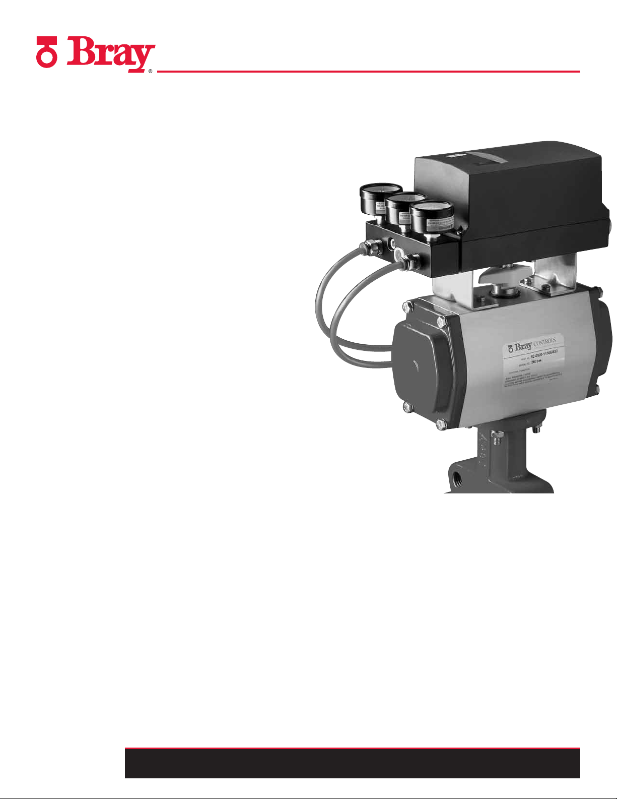
SERIES 6A
ELECTRO-pnEumATIC pOSITIOnER
OPERATION AND MAINTENANCE MANUAL
Page 2
Series 6A Operation & Maintenance – Table Of Contents
CONTENTS
Safety Information - Definition of terms . . . . . . . . 3
Introduction . . . . . . . . . . . . . . . . . . . . . . . . 4
Installation. . . . . . . . . . . . . . . . . . . . . . . . .5
Field Connections . . . . . . . . . . . . . . . . . . . . . 6
Calibration and Commissioning . . . . . . . . . . . . 11
Factory or Field Installable Options . . . . . . . . . . 20
Troubleshooting . . . . . . . . . . . . . . . . . . . . . 26
Service and Maintenance . . . . . . . . . . . . . . . . 29
Technical Data . . . . . . . . . . . . . . . . . . . . . . 30
Dimensional Drawings . . . . . . . . . . . . . . . . . 40
6A O & M : 2
All information herein is proprietary and condential and may not be copied or reproduced without the expressed written consent of BRAY INTERNATIONAL, Inc.
The technical data herein is for general information only. Product suitability should be based solely upon customer’s detailed knowledge and experience with their application.
Page 3

Series 6A Operation & Maintenance – Safety
SAFETY INFORMATION - DEFINITION OF TERMS
indicates a potentially hazardous situation which, if not avoided, could result in
Q WARNING
Q CAUTION
death or serious injury.
indicates a potentially hazardous situation which, if not avoided, may result in
minor or moderate injury.
NOTICE
Hazard-free use
This device left the factory in proper condition to be safely installed
and operated in a hazard-free manner. The notes and warnings in this
document must be observed by the user if this safe condition is to be
maintained and hazard-free operation of the device assured.
• Take all necessary precautions to prevent damage due to rough
handling, impact, or improper storage. Do not use abrasive
compounds to clean, or scrape its surfaces with any objects.
• Conguration and calibration procedures are described in this
document. Proper conguration and calibration is required
for the safe operation.
• The control system in which the unit is installed must have
proper safeguards to prevent injury to personnel, or damage to
equipment, should failure of system components occur.
• This document does not cover every detail about every version
of the product described. It cannot take into account every
potential occurrence in installation, operation, maintenance
and use.
• If situations transpire that are not documented in sufcient
detail, please request the required information from the Bray
Distributor or Representative responsible for your area.
used without the safety alert symbol indicates a potential situation which, if not
avoided, may result in an undesirable result or state, including property damage.
Qualified Personel
A qualied person in terms of this document is one who is familiar
with the installation, commissioning and operation of the device and
who has appropriate qualications, such as:
• Is trained in the operation and maintenance of electric
equipment and systems in accordance with established safety
practices.
• Is trained or authorized to energize, de-energize, ground, tag
and lock electrical circuits and equipment in accordance with
established safety practices.
• Is trained in the proper use and care of personal protective
equipment (PPE) in accordance with established safety
practices.
• Is trained in rst aid.
• In cases where the device is installed in a potentially
explosive (hazardous) location – is trained in the operation,
commissioning, operation and maintenance of equipment in
hazardous locations.
All information herein is proprietary and condential and may not be copied or reproduced without the expressed written consent of BRAY INTERNATIONAL, Inc.
The technical data herein is for general information only. Product suitability should be based solely upon customer’s detailed knowledge and experience with their application.
6A O & M : 3
Page 4

Series 6A Operation & Maintenance – Introduction
INTRODUCTION
The Bray S6A is a microcontroller based positioner for pneumatic
actuators. The S6A converts an analog current signal into a
valve position pressure signal and offers positioner, valve and
actuator diagnostics using a variety of communication protocols.
Optional modules can be added for full range valve position
feedback, valve open/close verication, preset alarm warnings
and electromagnetic compatibility.
Principles of Operation
The operation of the S6A can be described in three parts; the user
dened setpoint, the pneumatic actuator air supply, and the S6A
internal controller. The user dened setpoint, which is provided
by the incoming analog signal or the communication protocol,
tells the positioner where to set the actuator. The pneumatic
actuators air supply provides the power to work the valve, and the
S6A internal microcontroller monitors the actuator position and
provides diagnostics to the end user.
When the microcontroller sees a deviation between the actual
position of the actuator and the provided setpoint it will pulse the
internal piezo electric valve in order to let air ll the corresponding
actuator chambers and drive the actuator from the pneumatic
supply lines. Once this deviation is within a desired tolerance or
“dead band” the microcontroller will stop the pulsing. Using this
process, the S6A only consumes air when it is needed, meaning it
will pay for itself within a short period of time.
Electrical Operation
The standard S6A requires 4 to 20mA loop power for all of the
internal electronics. It can be installed in a two wire, three wire,
or four wire architecture. There is no need to run separate power
and signal wiring. The S6A positioners with communication
modules get their power directly from the network. All of the
wiring diagrams for the different versions of the S6A and any
optional modules are shown in the “Field Connections” portion
of this manual.
Mechanical Operation
The S6A requires a pneumatic supply in the range of 20 - 102 psi
(1.4 - 7 BAR). Using this pneumatic supply, the S6A will position
the actuator and valve precisely where it needs to be to regulate
the process. Once in the settled state, the S6A has one of the lowest
air bleed rates in the market. The S6A requires a pneumatic supply rated at Class 2 in accordance with ISO 8573-1. An optional
lter can be installed upstream of the S6A to clean incoming air.
Diagrams are provided showing how to make the pneumatic connections in the “Field Connections”portion of this manual.
6A O & M : 4
All information herein is proprietary and condential and may not be copied or reproduced without the expressed written consent of BRAY INTERNATIONAL, Inc.
The technical data herein is for general information only. Product suitability should be based solely upon customer’s detailed knowledge and experience with their application.
Page 5
Series 6A Operation & Maintenance – Installation
INSTALLATION
Mounting to an Actuator
All Bray S6A positioners are suitable for mounting on Bray pneumatic actuators with the use of a standard mounting bracket. With
proper mounting hardware, the S6A positioner can be installed
onto other linear or quarter turn pneumatic actuators. The standard mounting position is to orient the unit directly over the
pneumatic actuator using the NAMUR mounting arrangement in
such a way that the LCD and pushbuttons are easily accessible.
If the positioner is to be mounted on a vertical pipe, it is recommended that the unit be positioned with the conduit entries on the
bottom to prevent condensation from entering the positioner by
way of conduit. In all cases, the conduit should be positioned to
prevent drainage into the positioner.
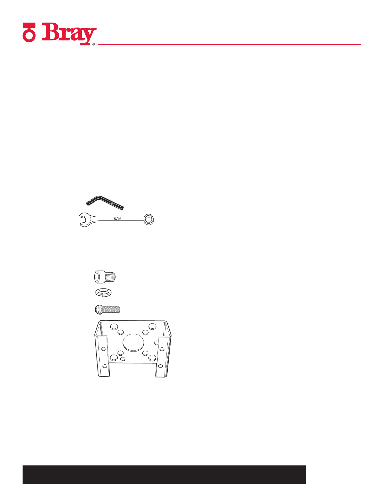
Tools Needed:
• 5mm Allen Key
• 5/16" Wrench
Parts Needed:
Item Qty.
The positioner should be mounted to
the actuator as follows:
1. Turn the positioner upside down and align the provided mounting bracket over the positioners output shaft. The bracket
should align with the four threaded holes around the output
shaft.
2. Using the 5mm allen key afx the mounting bracket to the
positioner using the four lockwashers and mounting bolts [A].
3. Turn the positioner right side up and position the output shaft
so that the atted side is facing you.
4. Insert the coupler over the output shaft, ensuring that the
couplers set screw is in alignment with the at of the shaft.
Tighten the couplers set screw.
5. Place the yellow indicator on the base of the coupler.
6. Mount the positioner on top of the actuator and tighten it using
the 5/16" wrench and the four mounting bolts [B].
Refer to the S6A Quick Start Guide for details.
Mounting Bolts [A] (4)
Lockwashers (4)
Mounting Bolts [B] (4)
Mounting Bracket (1)
All information herein is proprietary and condential and may not be copied or reproduced without the expressed written consent of BRAY INTERNATIONAL, Inc.
The technical data herein is for general information only. Product suitability should be based solely upon customer’s detailed knowledge and experience with their application.
6A O & M : 5
Page 6
Series 6A Operation & Maintenance – Field Connections
4 ... 20 mA
BE1 = Binary Input
7
8
9
10
+
–
J
6
4 ... 20 mA
BE1 = Binary Input
7
8
9
10
+
–
J
6
2
3
4
5
+
–
J
6
7
8
9
10
4 ... 20 mA
BE1 = Binary Input
4 ... 20 mA
BE1 = Binary Input
7
8
9
10
+
–
J
6
1) Jumper between 5 and 7 only for three-wire system
2
3
4
5
+
–
J
6
7
8
9
10
4 ... 20 mA
0/4 ... 20 mA
2
3
4
5
+
–
6
7
8
9
10
18 ... 30 V
J
+
–
BE1 = Binary Input
BE1 = Binary Input
1)
4 ... 20 mA
BE1 = Binary Input
7
8
9
10
+
–
J
6
HART
modem
PC/Laptop
R 250 W if req.
1)
3
Only required with current sources not conforming to HART1)
2
3
4
5
+
–
I
l
y
= 4 ... 20 mA
6
7
8
l
W-
l
H+
1) Jumper between 5 and 7 only for three-wire system
2
3
4
5
+
–
J
6
7
8
9
10
4 ... 20 mA
0/4 ... 20 mA
2
3
4
5
+
–
6
7
8
9
10
18 ... 30 V
J
+
–
BE1 = Binary Input
BE1 = Binary Input
1)
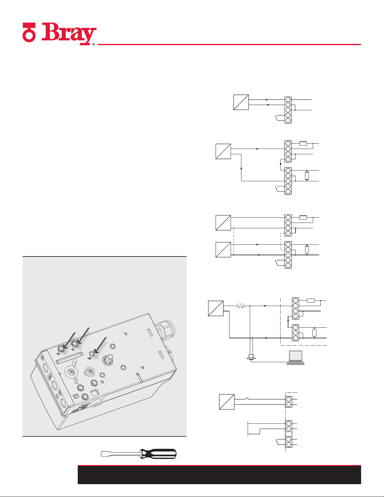
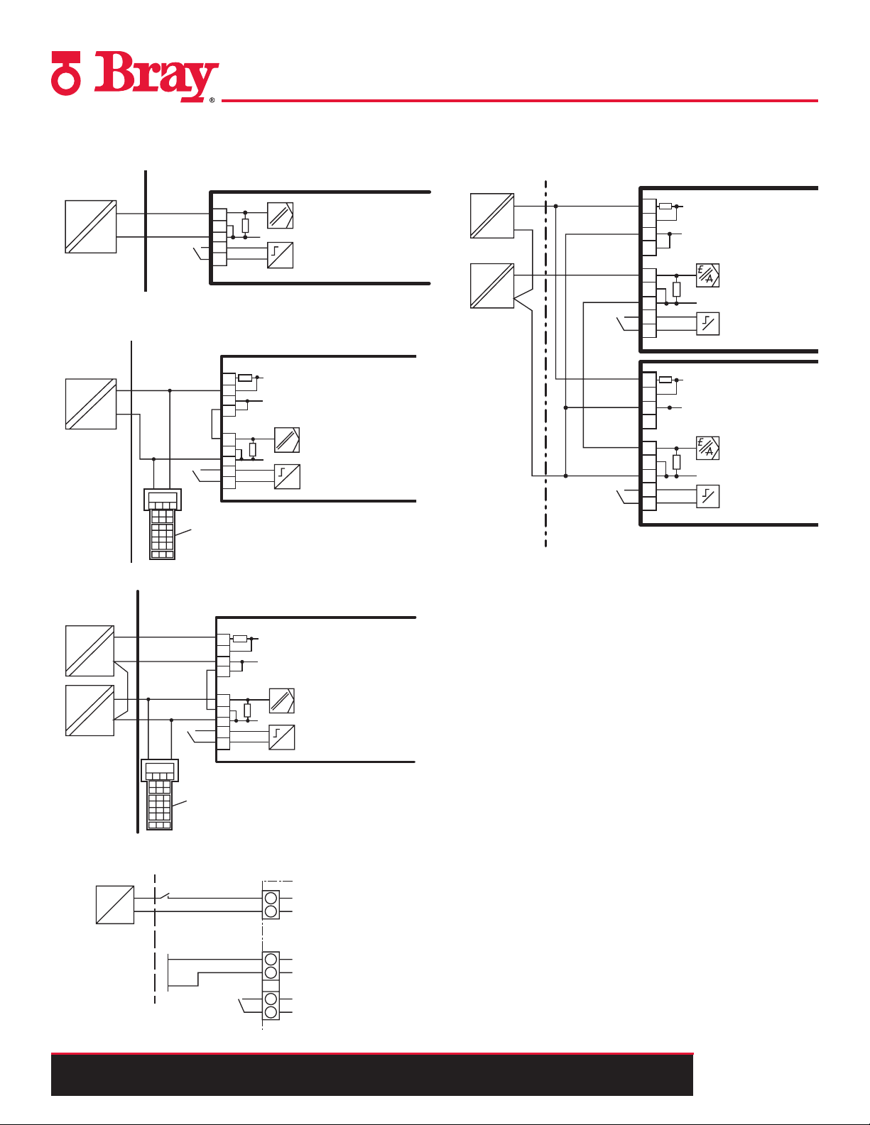
FIELD WIRING
Each S6A is provided with two conduit entries for power/incoming analog signal of the main unit and any optional modules.
Please refer to the wiring diagrams referenced in this document when connecting the positioner and any optional modules.
It is essential to install the optional modules before connecting the positioner electrically. Refer to the following “Technical
Description” portion of this manual for relevant power distribution sizing information when installing a S6A positioner and its
optional modules.
Safety Notes:
• Local regulations regarding hazardous environments must be
followed when installing this device in a hazardous location.
• The conduit connections must be properly sealed to maintain
the weatherproof integrity of the actuator enclosure.
• Never connect the current input (terminals 6 and 7 as shown
on the diagrams to the right) to a power source; the positioner
will probably be destroyed in that case. Always use a current
source with a maximum output current of I = 20 mA.
• To maintain auxiliary power, the input current must be a minimum of 3.6 mA.
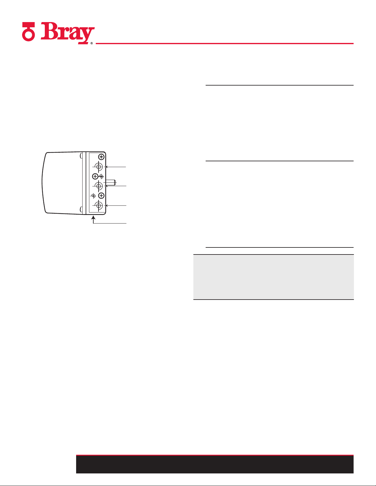
Note: The plastic enclosure is metallized from inside to
increase the electromagnetic compatibility (EMC) with
respect to high-frequency radiation. The shield is connected
to the threaded bush shown in Figure 1 such that it is electrically conductive. This protection is effective only if you
connect at least one of the bushes to the grounded control
valves through electrically conductive (bare) attachments.
1.
2.
3.
Figure 1.
Tools Needed:
• Instrument Screwdriver
I. General Area
1. Two Wire
+
4 ... 20 mA
J
6
7
–
8
9
BE1 = Binary Input
10
2. Two Wire Connection When Using a 2/3/4 Wire Device
2
+
J
4 ... 20 mA
3
4
5
6
7
–
8
BE1 = Binary Input
9
10
3. Three/Four Wire
+
2
18 ... 30 V
J
1) Jumper between 5 and 7 only for three-wire system
0/4 ... 20 mA
3
–
4
5
1)
+
6
7
–
8
9
10
BE1 = Binary Input
4. HART
1)
l
= 4 ... 20 mA
y
2
l
H+
3
4
5
6
l
7
W-
8
PC/Laptop
I
Only required with current sources not conforming to HART1)
3
R 250 W if req.
+
–
HART
modem
5. Probus DA/DP, Foundation Fieldbus
≤ 30 V
+
–
≤ 24 V
+
–
Input for safety shutdown (activated using coding jumper)
1)
1)
81
82
6
7
9
BE1 = Binary Input
10
6A O & M : 6
All information herein is proprietary and condential and may not be copied or reproduced without the expressed written consent of BRAY INTERNATIONAL, Inc.
The technical data herein is for general information only. Product suitability should be based solely upon customer’s detailed knowledge and experience with their application.
Page 7
4 ... 20 mA
BE1 = Binary Input
7
8
9
10
+
–
J
6
Input for safety shutdown (activated using coding jumper)
1)
≤ 30 V
≤ 24 V
+
–
BE1 = Binary Input
7
9
10
+
–
6
1)
81
82
1)
HART
modem
PC/Laptop
R 250 W if req.
1)
3
Only required with current sources not conforming to HART1)
2
3
4
5
+
–
I
l
y
= 4 ... 20 mA
6
7
8
l
W-
l
H+
1) Jumper between 5 and 7 only for three-wire system
2
3
4
5
+
–
J
6
7
8
9
10
4 ... 20 mA
0/4 ... 20 mA
2
3
4
5
+
–
6
7
8
9
10
18 ... 30 V
J
+
–
BE1 = Binary Input
BE1 = Binary Input
1)
Series connection of 2 positioners, e.g. split range (auxiliary power wired separately), EEx i
Series 6A Operation & Maintenance – Field Connections
II. Hazardous Area (Intrinsically Safe)
A. Two Wire
Non-hazardous area Hazardous area, Zone 1
EEx
Intrinsically safe
power source
4 to 20 mA
B. and C. Two Wire Connection When Using a 2/3/4 Wire
Device and HART
Non-Hazardous
area
EEx
I
Intrinsically safe
power source
Hazardous area, Zone 1
+
4 to 20 mA
6
7
8
9
10
2
3
4
5
6
7
8
9
10
HART Communicator
6A-6DR52**-*E*** only
#
Positioner
E
A
#
Positioner
Binary input 1
Binary input 1
Multiple Positioners Field Wiring
Split Range
Auxiliary power
Intrinsically safe power sources
Entire positioning
Non-hazardous area Hazardous area, Zone 1
EEx
EEx
L+
V
I
I
range I
+ 18 to 30 V
M
y
M
+ 0/4 to 20 mA
y
2
3
4
5
6
7
8
9
10
2
3
4
5
6
7
8
9
10
Positioning range 1
BE1
#
Positioning range 1
BE1
#
D. Three/Four Wire
Non-hazardous area Hazardous area, Zone 1
18 to 30 V
+
EEx
I
EEx
I
Intrinsically safe
power source
E. Probus DA/DP, Foundation Fieldbus
Non-Hazardous Hazardous area, Zone 1
Power Supply
4 to 20 mA
+
*)
–
+
2
3
4
5
6
*)
7
8
9
10
HART Communicator
6A-6DR52**-*E*** only
≤ 24 V
–
Input for safety shutdown (activated using coding jumper)
Positioner
E
A
#
*) Three-wire connection only
81
82
6
7
9
BE1 = Binary Input
10
Binary input 1
All information herein is proprietary and condential and may not be copied or reproduced without the expressed written consent of BRAY INTERNATIONAL, Inc.
The technical data herein is for general information only. Product suitability should be based solely upon customer’s detailed knowledge and experience with their application.
6A O & M : 7
Page 8
Series 6A Operation & Maintenance – Field Connections
Connecting Pneumatic Supply Lines
Refer to the Technical Data portion of this manual for specications regarding air quality.
The S6A is equipped with three pneumatic connections, Y1, Y2
and PZ. PZ is for the pneumatic supply and Y1 and Y2 are used
to supply the pneumatic actuator. The S6A can also be equipped
with a pressure gauge block for monitoring supply and actuating
pressure and a lter to ensure that the S6A is receiving clean air.
Proceed as follows to make the pneumatic connections:
Refer to Figure 2.
Y1
PZ
Y2
E
Figure 2. - Pneumatic connection on the standard controller
1. If required, connect the pressure gauge block for supply air
and actuating pressure.
2. Connect supply air to PZ.
Connection using female thread G1/4 DIN 45141
or 1/4" NPT:
• PZ supply air 20psi to 102psi (1.4 to 7 bar)
• Y1: actuating pressure for single and double-acting
actuators
• Y2: actuating pressure for double-acting actuators
• E: exhaust air outlet; remove the attenuator if required.
For double-acting actuators, connect actuating pressures
Y1 or Y2 depending on the desired safety position. The
three pneumatic connections will go to the following
safety position in case of electrical auxiliary power supply failure:
• Y1: single-acting, depressurized
• Y1: double-acting, max. actuating pressure/supply air
pressure.
• Y2: double-acting, depressurized
Note: Besides continuous air consumption, the positioner may
try to compensate the position deviation due to leakage. This
will lead to premature wear in the entire control unit. To prevent
this ensure that all pneumatic connections are properly sealed
and perform regular maintenance on their ttings.
6A O & M : 8
All information herein is proprietary and condential and may not be copied or reproduced without the expressed written consent of BRAY INTERNATIONAL, Inc.
The technical data herein is for general information only. Product suitability should be based solely upon customer’s detailed knowledge and experience with their application.
Page 9
Series 6A Operation & Maintenance – Field Connections
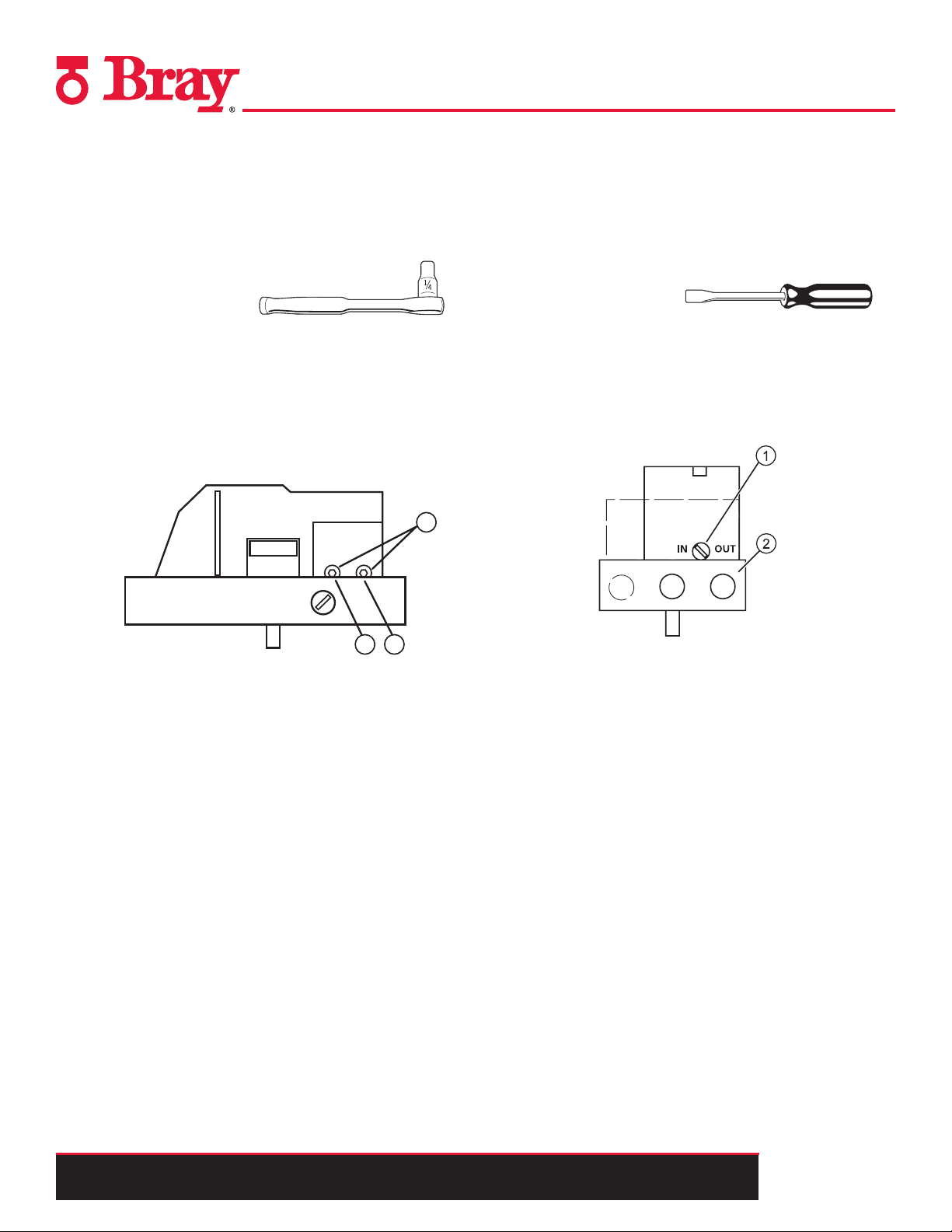
1
2
3
Restrictors
The S6A is equipped with air restrictors to reduce the air output to
achieve actuating times of T > 1.5 s for small actuators. Restrictors
1 and 2 are used for this purpose.
Tools Needed:
• Hexagon socket 2.5 mm
Refer to Figure 3.
When turned clockwise, they reduce the air output and nally shut
it off.
In order to set the restrictors, it is recommended to close them and
then open them slowly.
In case of double-acting actuators, ensure that both restrictors
have approximately the same setting.
Purging
The S6A is equipped with a purge air switch that allows the
actuator to purge air either inside of the unit or directly outside.
When the enclosure is open, the purge air switch above the
pneumatic terminal strip on the pneumatic block can be accessed.
Tools Needed:
• Instrument Screwdriver
Refer to Figure 4.
In the IN position, the enclosure is ushed from inside with a
small volume of clean and dry instrument air.
In the OUT position, the purge air is directed towards outside of
the unit.
Figure 3. - Air Restrictor
➀Restrictor for Y1
➁Restrictor for Y2, only in the version for double-acting
actuators
➂Hexagon socket-head screw 2.5 mm
Figure 4. - Purge Air Switch
➀Purge Air Switch
➁Pneumatic Block
All information herein is proprietary and condential and may not be copied or reproduced without the expressed written consent of BRAY INTERNATIONAL, Inc.
The technical data herein is for general information only. Product suitability should be based solely upon customer’s detailed knowledge and experience with their application.
6A O & M : 9
Page 10
Series 6A Operation & Maintenance – Field Connections
Natural Gas as an Actuator Medium
The S6A can also be operated with natural gas as an actuator
medium. When operating the positioner with natural gas, you
must follow and adhere to the following safety notes:
1. Only the “EEx ia” version of the positioner and optional
modules with the “EEx ia” type of protection may be operated
with natural gas. Positioners with other types of protection,
i.e. ameproof enclosures for zones 1 and 2 are not permitted.
2. Do not operate the positioner with natural gas in closed spaces.
3. Natural gas is continuously blown off in the servo-drive
depending on the model. Special care must therefore be taken
during maintenance activities near the positioner. Always
ensure that the immediate surroundings of the positioner are
adequately ventilated.
4. The mechanical limit switch module may not be used when
operating the positioner with natural gas.
5. Depressurize the devices operated with natural gas adequately
during maintenance activities. Open the cover in an explosionfree atmosphere and depressurize the device for at least two
minutes.
Normally you operate the positioner with compressed air. Natural
gas has been approved as an actuator medium for intrinsically
safe positioners with the “EEx ia” type of protection. Only use
natural gas which is clean, dry and free from additives.
The positioner releases the used natural gas through the exhaust
air outlet E (see Figure 2). The exhaust air outlet E is equipped
with an attenuator. As an alternative to this standard conguration,
the exhaust air outlet can be replaced with a G¼ screwed tting.
You have to dismantle the attenuator for this purpose. Natural gas
escapes parallel to the exhaust air outlet E, from the enclosure
vent at the bottom side of the device, and from the control air
outlet near the pneumatic connections. This escaping natural gas
cannot be collected and carried off. When using natural gas as an
actuator medium refer to Figure 5 for maximum bleed off values.
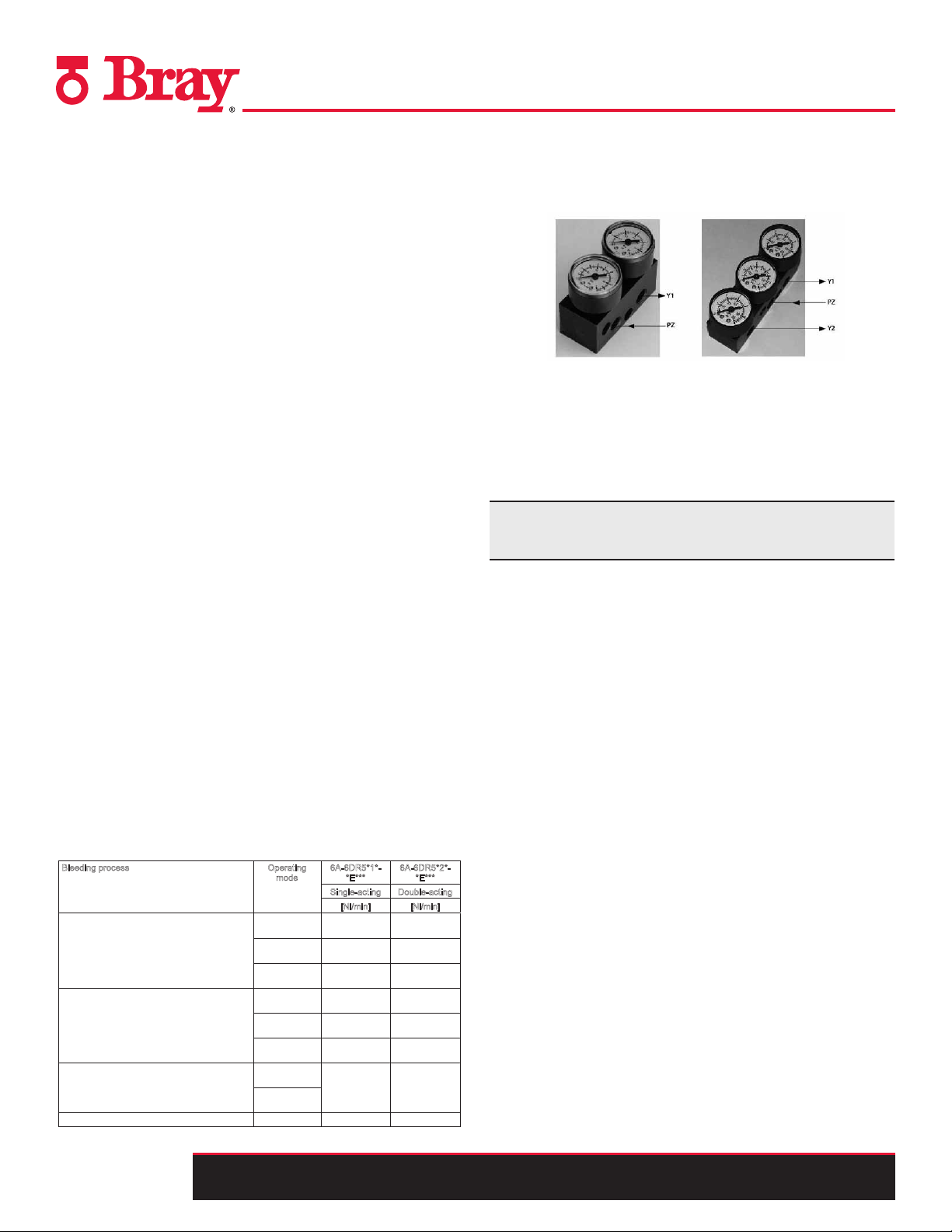
Optional Accessories
1. Pressure Gauges – used to measure and indicate supply and
actuating pressures
2. Filter – used to clean the supply medium
3. Non Contacting/External Position Detection System – used
for harsh environments
4. SIMATIC PDM Operation Software – used for online
diagnostics of the S6A
Contact your Bray representative for specic requirements for
your intended application.
Figure 5. Maximim bleed off values
Bleeding process Operating
Bleed the enclosure volume through the bottom
side of the device. Purge air switch is at "IN":
Bleed through the control air outlet near the
pneumatic connections:
Bleed through the exhaust air outlet E
6A O & M : 10
All information herein is proprietary and condential and may not be copied or reproduced without the expressed written consent of BRAY INTERNATIONAL, Inc.
The technical data herein is for general information only. Product suitability should be based solely upon customer’s detailed knowledge and experience with their application.
ode
m
Operation,
typical
Operation,
max.
Error case,
max.
Operation,
typical
Operation,
max.
Error case,
max.
Operation,
max.
Error case,
max.
6A-6DR5*1*-
*E***
Single-acting Double-acting
[
Nl/min] [Nl/min]
0.14 0.14
0.60 0.60
60.0 60,0
1.0 2.0
8.9 9.9
66.2 91.0
358.21) 339
6
A-6DR5*2*-
*E***
1),
32.1 62.1 ]l[ .xaM emuloV
Page 11
Series 6A Operation & Maintenance – Calibration & Commissioning
CALIBRATION AND COMMISSIONING
Installing a New Unit
Please refer to the S6A Quick Start Guide for the Standard Unit.
Replacing a Unit
The S6A can be replaced in a running system where a S6A was
already in use without interrupting the process. By copying and
transferring the device and initialization data, it is possible to
commission a replacement positioner without needing to initialize it. The S6A uses the communication interface to transfer data.
When this is performed, it is crucial to perform a standard initialization of the replacement positioner as soon as possible because
the following properties can be ensured only after initializing:
• Optimum adjustment of the positioner as per the mechanical
and dynamic properties of the actuator.
• Unrestricted accuracy and dynamic behavior of the positioner.
• Deviation-free position of the hard-end stops.
• Accuracy of the maintenance data
Copy the initialization data and the device parameters as follows:
1. Read in the initialization data and the device parameters of the
positioner to be replaced. Use a suitable parameterization
tool for this purpose.
2. Save the data in the parameterization tool.
Note: If the positioner to be replaced has already been initialized
or congured using the parameterization tool, you need not read
in and save the device data.
Proceed as follows to replace a positioner in a running system:
3. Fix the actuator at its current position mechanically or
pneumatically.
4. Determine the actual position value.
– Read the actual position value on the digital display of
the positioner to be replaced.
Take note of the read value.
– If the electronic unit of the positioner is defective, mea-
sure the actual position value at the actuator or the valve.
Take note of the read value.
5. Dismantle the positioner.
6. Attach the lever arm of the positioner to be replaced to the
replacement positioner.
7. Install the replacement positioner on the control valve.
8. Set the transmission ratio selector of the replacement positioner
to the same position as that of the positioner to be replaced.
9. Use the parameterization tool to transfer the saved device and
initialization data to the replacement positioner.
10. If the displayed actual position value differs from the noted
value, correct the deviation by moving the friction clutch.
11. The replacement positioner is ready for operation when the
displayed and the noted values match.
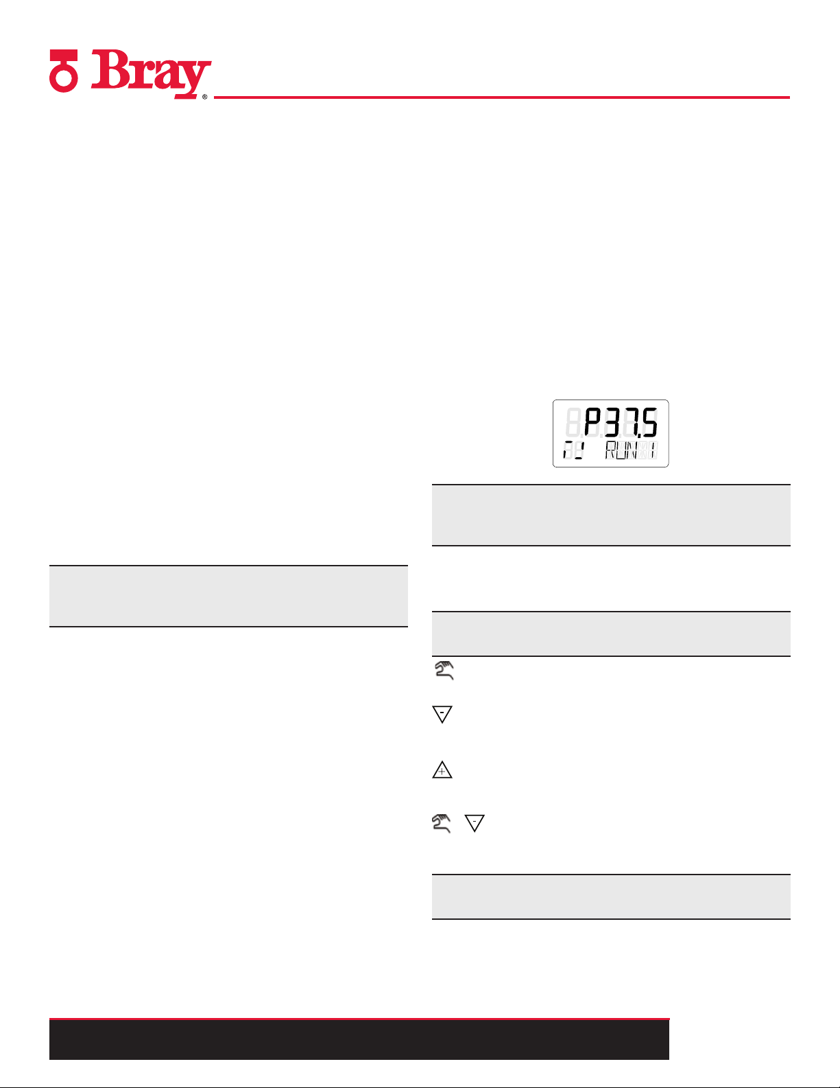
Operation
Reading the LCD screen
The S6A digital display has two lines, one on the bottom and one
on top. Each element on the top line has seven segments while
each element on the bottom line has fourteen. Contents of the display depend on the selected mode. Figure 6 below provides an
example of what the display will look like when the unit is powered on.
Figure 6.
Example Display
Note: When operated in temperature ranges below 14°F (-10°C),
the liquid crystal display of the positioner becomes sluggish and
the repetition rate display is reduced considerably.
Using the pushbuttons
The S6A is manually operated using three pushbuttons. The cover
of the positioner has to be removed in order to operate the buttons.
Note: The function of the buttons depends on the current
Operating Mode. As a general rule the following applies:
The operating mode button is used to select the modes and to
forward the parameters.
The decrement button is used to select parameter values when
conguring. You can use this button to move the actuator in
the manual mode.
The increment button is also used to select parameter values
when conguring. You can use the increment button to move
the actuator in the manual mode.
+ *Parameters are activated in the reverse order by press-
ing the operating mode button and the decrement button at
the same time
Note: The IP66/NEMA 4x degree of protection is not ensured
as long as the positioner is open.
All information herein is proprietary and condential and may not be copied or reproduced without the expressed written consent of BRAY INTERNATIONAL, Inc.
The technical data herein is for general information only. Product suitability should be based solely upon customer’s detailed knowledge and experience with their application.
6A O & M : 11
Page 12
Series 6A Operation & Maintenance – Calibration & Commissioning
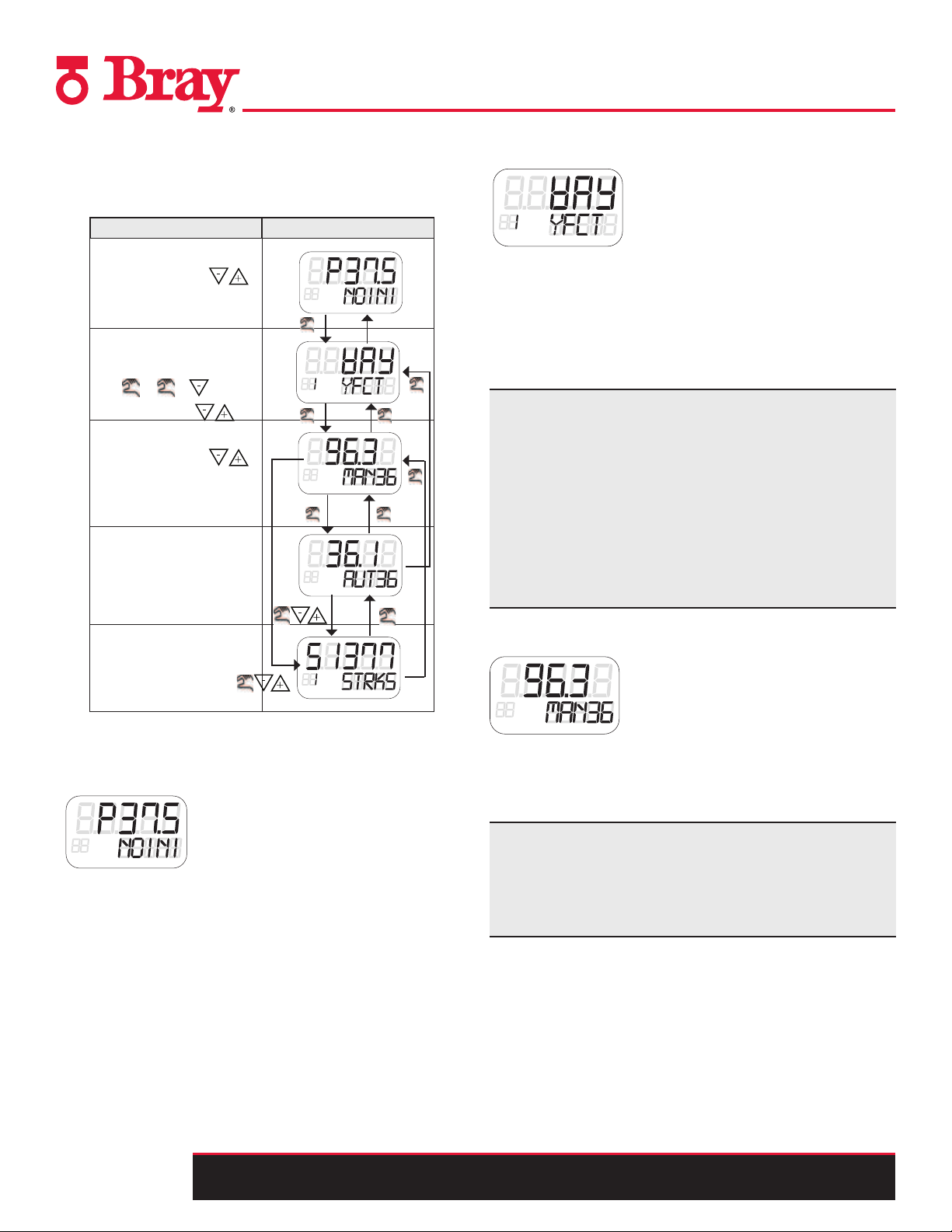
Operating Modes
The S6A has ve different operating modes described in detail
below. Refer to Figure 7 to navigate between modes.
Operating Mode Display
P- manual operation
change position with
Congure
select parameter
with
or +
change value with
Manual Operation
change position with
Automatic
> 5 s
> 5 s > 5 s
1x
PRST
> 5 s
> 2 s
1x
Configuration and initialization mode
To get to the “Conguration” mode, press the operating mode
button for at least 5 seconds. You can use the “Conguration”
mode to adjust the positioner individually as per your actuator
and start commissioning or initialization. The positioner reports
the “Conguration” mode with a congurable fault message. A
position feedback or display of limits A1 and A2 is not possible.
Note: If electrical auxiliary power supply fails when conguring,
the positioner responds as follows until the power supply is
reestablished:
• The positioner switches to the rst parameter.
• Settings of the values already congured are retained.
In order to save the changed parameter values, exit the
“Conguration” mode or switch to another parameter. When
the “Conguration” mode is restarted, the control in the digital
display switches to the last activated parameter.
Diagnostics
Figure 7. Operating Modes Display
> 2 s
> 2 s
> 2 s
P-manual mode (as-delivered condition)
The “P-manual mode” is preset for the positioner in the
as-delivered condition. The digital display of the positioner shows
the current potentiometer position in the upper line. “NOINI”
blinks in the second line of the digital display. You can move the
actuator using the decrement and increment buttons. Switch to
Conguration” and “Initialization mode” to adapt the actuator as
per the positioner.
Alarms or position feedbacks can be triggered only after
initializing the positioner completely.
Manual mode (MAN)
You can move the actuator using the decrement and increment
buttons in this mode. The setting selected here is retained
irrespective of the setpoint current and leakages, if any.
Note: To accelerate the actuator movement keep one of the
two direction buttons pressed and simultaneously press the
remaining direction. In the event of a failure of the power
supply, once the power is reestablished the positioner switches
to “Automatic” mode.
6A O & M : 12
All information herein is proprietary and condential and may not be copied or reproduced without the expressed written consent of BRAY INTERNATIONAL, Inc.
The technical data herein is for general information only. Product suitability should be based solely upon customer’s detailed knowledge and experience with their application.
Page 13

Series 6A Operation & Maintenance – Calibration & Commissioning
Automatic (AUT)
Automatic is the standard mode. In this mode, the positioner
compares the setpoint position with the actual position. The
positioner moves the actuator until the control deviation reaches
the congurable dead zone. A fault message is displayed if the
dead zone cannot be reached.
Diagnostics
Proceed as follows to call the “Diagnostics” mode from the
“Automatic” or “Manual” modes:
Press the three buttons of the positioner at the same time for at
least 2 seconds.
Current operating data can be called and displayed in this mode,
e.g.:
• Stroke number
• Number of changes in direction
Using the built in Diagnostics
The S6A has various monitoring functions with which changes on
the actuator and valve can be detected and signaled if applicable
when a selectable limit has been exceeded. This information may
be important for diagnosis of the actuator or valve and will help
to schedule preventative maintenance. The measuring data that is
monitored is listed below:
• Travel integral
• Number of changes in direction
• Alarm counter
• Self-adjusting dead zone
• Valve end limit position (for detection of valve seat wear or
deposits)
• Operating Hours (also according to temperature and travel
ranges) as well as min./max. temperature
• Operating Cycles of piezoelectric valves
• Valve positioning time
• Actuator leakages
The diagnostics display has similar structure to that of the
“Conguration” mode:
• The upper line shows the value of the diagnosis variable.
• The lower line shows the number and the abbreviation of the
displayed variable.
• Number of fault messages
Note: The “Automatic” and “Manual” modes remain set when
switching to the “Diagnostics” mode. The positioner responds
as per the set mode:
• The predened setpoint is used as a control variable in the
automatic mode.
• The last reached position is retained in the manual mode.
Some diagnostics values can be greater than 99999. In such a
case, the display switches over to the exponential view. Example:
The value “1234567” is shown as “1.23E6”.
In the event of a fault an error code will be shown on the lower
left hand corner of the display. There is a fault table in the
“Troubleshooting” section of this manual which explains what
each of these codes represents.
The following table provides an overview of values that can be
displayed. The last column contains “X” if the value can be set
to zero.
All information herein is proprietary and condential and may not be copied or reproduced without the expressed written consent of BRAY INTERNATIONAL, Inc.
The technical data herein is for general information only. Product suitability should be based solely upon customer’s detailed knowledge and experience with their application.
6A O & M : 13
Page 14

Series 6A Operation & Maintenance – Calibration & Commissioning
Overview of diagnostics values
Overview of Diagnostics Values
No. Abbreviation Meaning Values that can
1 STRKS Stroke number (Strokes) 0 ... 4.29E9 - X
2 CHDIR Changes of direction (Changes of Direction) 0 ... 4.29E9 - X
3 CNT Number of fault messages ( Counter) 0 ... 4.29E9 - X
4 A1CNT Number of alarms 1 (Alarm 1 Counter) 0 ... 4.29E9 - X
5 A2CNT Number of alarms 2 (Alarm 2 Counter) 0 ... 4.29E9 - X
6 HOURS Operating hours (Hours) 0 ... 4.29E9 Hours -
7 WAY Determined actuator travel (Way) 0 ... 130 mm or ° -
8 TUP Actuating time up (Travel Time Up) 0 ... 1000 s -
9 TDOWN Actuating time down (Travel Time Down) 0 ... 1000 s -
10 LEAK Leakage (Leakage) P 0.0 ... 100.0 % -
11 PST Monitoring of the partial stroke test OFF / ###.#, fdini,
12 PRPST Time since the last Partial-Stroke-Test ###, notSt, Sdtst,
13 NXPST Time until the next Partial-Stroke-Test ###, notSt, SdtSt,
14 DEVI General control valve fault OFF, 0.0 ... 100.0 % -
15 ONLK Pneumatic leakage OFF, 0.0 ... 100.0 - -
16 STIC Static friction/Slipstick effect OFF, 0.0 ... 100.0 % -
17 ZERO Zero point displacement OFF, 0.0 .. 100.0 % -
18 OPEN Displacement of upper end stop OFF, 0.0 ... 100.0 % -
19 PAVG Position average 0.0 ... 100.0 % -
20 P0 Potentiometer value of lower end stop (0%) 0.0 ... 100.0 % -
21 P100 Potentiometer value of upper end stop (100%) 0.0 ... 100.0 % -
22 IMPUP lmpulse length up (Impuls Length Up) 2 ... 160 ms -
23 IMPDN Impulse length down (Impuls Length Down) 2 ... 160 ms -
24 DBUP Dead zone up (Dead Band Up) 0.1 ... 10.0 % -
25 DBDN Dead zone down (Dead Band Down) 0.1 ... 10.0 % -
26 SSUP Slow step zone up (Short Step Zone Up) 0.1 ... 100.0 % -
27 SSDN Slow step zone down (Short Step Zone Down) 0.1 ... 100.0 % -
28 TEMP Current temperature -40 ... 85 °C -
29 TMIN Minimum temperature ("min/max pointer") -40 ... 85 °C -
30 TMAX Maximum temperature ("min/max pointer") -40 ... 85 °C -
31 T1 Number of operating hours in temperature range 1 0 ... 4.29E9 Hours -
32 T2 Number of operating hours in temperature range 2 0 ... 4.29E9 Hours -
33 T3 Number of operating hours in temperature range 3 0 ... 4.29E9 Hours -
34 T4 Number of operating hours in temperature range 4 0 ... 4.29E9 Hours -
35 T5 Number of operating hours in temperature range 5 0 ... 4.29E9 Hours -
36 T6 Number of operating hours in temperature range 6 0 ... 4.29E9 Hours -
b
e displayed
notSt, SdtSt,
fdtSt, notd, Strt
fdtSt
fdtSt
nit Reset
U
s for ###.# -
Days -
Days -
p
ossible
Series 6A with and without HART communications
Operation and Maintenance Manual, 09/2008, A5E00756809-03
6A O & M : 14
All information herein is proprietary and condential and may not be copied or reproduced without the expressed written consent of BRAY INTERNATIONAL, Inc.
The technical data herein is for general information only. Product suitability should be based solely upon customer’s detailed knowledge and experience with their application.
Page 15

Series 6A Operation & Maintenance – Calibration & Commissioning
No. Abbreviation Meaning Values that can
b
e displayed
U
nit Reset
p
ossible
37 T7 Number of operating hours in temperature range 7 0 ... 4.29E9 Hours -
38 T8 Number of operating hours in temperature range 8 0 ... 4.29E9 Hours -
39 T9 Number of operating hours in temperature range 9 0 ... 4.29E9 Hours -
40 VENT1 Number of switching cycles of pilot valve 1 0 ... 4.29E9 - -
41 VENT2 Number of switching cycles of pilot valve 2 0 ... 4.29E9 - -
42 STORE Save the current value as "last maintenance" (press
the increment button for 5 s) (Store)
- - -
43 PRUP Prediction up 1 ... 40 - -
44 PRDN Prediction down 1 ... 40 - -
45 WT00 Number of operating hours in the actuating range
WT00
0 ... 4.29E9 Hours X
46 WT05 Number of operating hours in the actuating range
WT05
0 ... 4.29E9 Hours X
47 WT10 Number of operating hours in the actuating range
WT10
0 ... 4.29E9 Hours X
48 WT30 Number of operating hours in the actuating range
WT30
0 ... 4.29E9 Hours X
49 WT50 Number of operating hours in the actuating range
WT50
0 ... 4.29E9 Hours X
50 WT70 Number of operating hours in the actuating range
WT70
0 ... 4.29E9 Hours X
51 WT90 Number of operating hours in the actuating range
WT90
0 ... 4.29E9 Hours X
52 WT95 Number of operating hours in the actuating range
WT95
0 ... 4.29E9 Hours X
Diagnostic value 53
No. Abbreviation Meaning Values that can
b
e displayed
U
nit Reset
p
ossible
53 mA Setpoint current 0.0 to 20.0 mA --
Overview of Diagnostics Values (cont.)
No. Abbreviation Meaning Values that can
37 T7 Number of operating hours in temperature range 7 0 ... 4.29E9 Hours -
38 T8 Number of operating hours in temperature range 8 0 ... 4.29E9 Hours -
39 T9 Number of operating hours in temperature range 9 0 ... 4.29E9 Hours -
40 VENT1 Number of switching cycles of pilot valve 1 0 ... 4.29E9 - -
41 VENT2 Number of switching cycles of pilot valve 2 0 ... 4.29E9 - -
42 STORE Save the current value as "last maintenance" (press
the increment button for 5 s) (Store)
43 PRUP Prediction up 1 ... 40 - -
44 PRDN Prediction down 1 ... 40 - -
45 WT00 Number of operating hours in the actuating range
WT00
46 WT05 Number of operating hours in the actuating range
WT05
47 WT10 Number of operating hours in the actuating range
WT10
48 WT30 Number of operating hours in the actuating range
WT30
49 WT50 Number of operating hours in the actuating range
WT50
50 WT70 Number of operating hours in the actuating range
WT70
51 WT90 Number of operating hours in the actuating range
WT90
52 WT95 Number of operating hours in the actuating range
WT95
Diagnostic value 53
b
e displayed
- - -
0 ... 4.29E9 Hours X
0 ... 4.29E9 Hours X
0 ... 4.29E9 Hours X
0 ... 4.29E9 Hours X
0 ... 4.29E9 Hours X
0 ... 4.29E9 Hours X
0 ... 4.29E9 Hours X
0 ... 4.29E9 Hours X
nit Reset
U
No. Abbreviation Meaning Values that can
53 mA Setpoint current 0.0 to 20.0 mA --
Series 6A with and without HART communications
Operation and Maintenance Manual, 09/2008, A5E00756809-03
b
e displayed
nit Reset
U
p
ossible
p
ossible
All information herein is proprietary and condential and may not be copied or reproduced without the expressed written consent of BRAY INTERNATIONAL, Inc.
The technical data herein is for general information only. Product suitability should be based solely upon customer’s detailed knowledge and experience with their application.
6A O & M : 15
Page 16

Series 6A Operation & Maintenance – Calibration & Commissioning
Parameter Function Parameter Values Description
1)YFCT Typeofpositionactuator
2)YAGL Angleofrotation
3)YWAY RangeofStroke
4)INITA Initialization(automatic)
5)INITM Initialization(manual)
6)SCUR Currentrangeofsetpoint
7)SDIR SetpointSetup
8)SPRA Setpointsplitrangestart
9)SPRE Setpointsplitrangeend
10)TSUP SetpointrampOPEN
11)TSDO SetpointrampCLOSED
12)SFCT SetpointFunction
13)SLO
SetpointTurningPoint
…33)SL20
34)DEBA DeadZoneofClosedLoopController
35)YA Startofthemanipulated
variablelimit
36)YE Endofthemanipulated
variablelimit
37)YNRM Manipulatedvariable
scaling
38)YDIR DirectionofManipulated
Variable
39)YCLS Manipulatedvariabletight
closing
40)YCDO Lowervaluefortight
closing
Turn Automatically sets 2) YAGL to 90◦
WAY Used for linear actuators
LWAY Used for linear actuators
ncSt Used for a non-contacting position sensor on a part
turn actuator
-ncSt Used for a non-contacting position sensor on a part
turn actuator with a reverse direction of action
ncSL Used for linear actuators
ncSLL Used for linear actuators
33◦
90
◦
Used for linear actuators
Used for linear actuators
NOINI | no/ ###.# | Strt Starts the automatic initialization process
NOINI | no/ ###.# | Strt Starts the manual initialization process
0 MA 0 MA only available for 3 to 4 wire connections.
4 MA Factory setting.
riSE
FALL
Used to reverse the direction of the action of the
setpoint. Factory setting is “rise”
0.0 … 100.0 Used to limit the setpoint. Factory setting is “0”
0.0 … 100.0 Factory setting is “100”
Auto / 0 … 400
0 … 400
1 – 25
1 – 33
Limits the speed of change of the effective setpoint.
Factory setting is “0”
Equal Percentage. Linearizes valve characteristics.
Factory setting is “Lin”
1 – 50
n1 – 25
Inverse equal percentage
n1 – 33
n1 – 50
FrEE Freely Adjustable
0.0 … 100.0 Assigns a flow metric to each setpoint interpolation
in units of 5%.
Auto / .1 … 10.0 Adjust the dead zone to the requirements of the
control loop. Factory setting is “Auto”
0.0 … 100.0
Used to limit the mechanical actuator travel from
stop to stop to the configured values. “YE” must
0.0 … 100.0
always be larger than “YA”. Factory setting is “100”
MPOS Mechanical position from 0 to 100% between hard
stops.
FLOW Scaling from 0 to 100% over the range between
“YA” and “YE”
riSE
FALL
No
uP
Do
Used to set the direction of action of the display and
the position feedback Iy. Factory setting is “riSE”
Used to move the valve into its seat with the
maximum force of the actuator. Factory setting is
“No”
uP do
0.0 … 0.5 … 100% Factory setting is “0.5”
6A O & M : 16
All information herein is proprietary and condential and may not be copied or reproduced without the expressed written consent of BRAY INTERNATIONAL, Inc.
The technical data herein is for general information only. Product suitability should be based solely upon customer’s detailed knowledge and experience with their application.
Page 17

Series 6A Operation & Maintenance – Calibration & Commissioning
41)YCUP Uppervaluefortight
closing
42)BIN12) FunctionofBE1
43)BIN22) FunctionofBE2
44)AFCT3) AlarmFunction
0.0 … 99.5 … 100% Used to set the value for tight “Tight closing below”
and “Tight closing above”. Factory setting is “99.5”
Normally
Open
Normally
Closed
Functions while in binary input mode.
OFF Factory setting.
on -on Binary message from peripherals
bloc1 Used to lock the configuration operation
bloc2
uP -uP
doWn -doWn
Actuator regulating to the valve specified by
parameters “YA” and “YE”
StoP -StoP Piezo valves are blocked. Actuator remains at last
position.
PST -PST Used to trigger a partial stroke test
Normally
Open
Normally
Closed
Functions while in binary input mode.
OFF Factory setting.
on -on Binary message from peripherals
uP -uP
doWn -doWn
Actuator regulating to the valve specified by
parameters “YA” and “YE”
StoP -StoP Piezo valves are blocked. Actuator remains at last
position.
PST -PST Used to trigger a partial stroke test
Normal Inverted
Off
Used to determine the value at which going above or
below a given offset or angle will result in a
message.
45)A1 Triggerthreshold,alarm1
46)A2 Triggerthreshold,alarm2
47)FCT3) Functionforfault
messageoutput
48)TIM Monitoringtimefor
settingoffaultmessage
49)LIM Responsethresholdfor
faultmessage
50)PRST Preset(factorysetting)
51)XDIAG Activationofextended
diagnostics
52)FSTY SafetySeating
0.0 … 10.0 … 100 %
Used to specify when an alarm should be displayed.
0.0 … 90.0 …100%
Normal Inverted
Cannot be switched off. Can be suppressed by
switching to “No Automatic Mode”
Auto / 0 … 100 Used to set the time in seconds that the positioner
must have reached the regulated condition.
Auto / 0 … 100 Used to set a value for the permissible size of the
regulation device to trigger a fault message.
no
Strt
Used to restore factory settings and reset
initialization. Press increment button for 5 seconds.
oCAY
OFF
Used to activate extended diagnostics.
On1
On2
On3
FSVL Actuator controlled using the parameterization safety
point. Effective after a power failure.
FSSP Actuator controlled using the last effective set point
FSAC Valves move to location based on spring force.
(Factory Defined)
All information herein is proprietary and condential and may not be copied or reproduced without the expressed written consent of BRAY INTERNATIONAL, Inc.
The technical data herein is for general information only. Product suitability should be based solely upon customer’s detailed knowledge and experience with their application.
6A O & M : 17
Page 18

Series 6A Operation & Maintenance – Calibration & Commissioning
53)FSTI MonitoringPeriodfor
settingthesafetyseating
54)FSVL SafetySetpoint
55)STNR StationNumber
56)IDENT Deviceoperatingmode
(IDNo.)
0 … 100 (s). Once this set value expires the positioner
switches to its safety position. (Factory defined at 0)
0.0 … 100.0 (%). Default value of the safety position. (Factory
setting is 0%)
0 … 126 Independent value for each station. (Default position
is 126)
0 Profile Compliant. Can be replaced with other
positioners complying with Profibus PA profile 3.0
1 Compliant with Extensions (Factory Defined).
Parameter Function Parameter Values Description
A. PST Partial Stroke Test Used to activate the partial stroke test for cyclic or
manual test of up/down and servo solenoid valves.
A1.STPOS Starting position 0.0 … 100.0 Start position in %. Factory setting is “100.0”
A2.STTOL Starting tolerance 0.1 … 2.0 … 10.0 Start position tolerance in %. Factory setting is
“2.0”
A3.STEP Step height 0.1 ..10.0 ..100.0 Step height of partial stroke test in %
A4.STEPD Step Direction uP / do / uP do Step direction of partial stroke test. Factory setting
is “do”
A5.INTRV Test Interval OFF / 1 … 365 Interval time for cyclic partial stroke in days. “Off”
A6.PSTIN Partial Stroke ref. step time NOINI / (C) ###.# /
Fdini / rEAL
A7.FACT1 Factor 1 0.1 … 1.5 … 100.0 Factor for the formation of limit threshold 1. “1.5”
A8.FACT2 Factor 2 0.1 … 3.0 … 100.0 Factor for the formation of limit threshold 2. “3.0”
A9.FACT3 Factor 3 0.1 … 5.0 … 100.0 Factor for the formation of limit threshold 3. “5.0”
b. DEVI General Control Valve Fault Test for dynamic monitoring of control valve
b1.TIM Time constant Auto / 1 … 400 Defines the attenuation effect of the low-pass filter.
b2.LIMIT Limit 0.1 … 1.0 … 100.0 Sets a base limit in %. “1.0”
b3.FACT1 Factor 1 0.1 … 5.0 … 100.0 Factor for the formation of limit threshold 1. “5.0”
b4.FACT2 Factor 2 0.1 ..10.0..100.0 Factor for the formation of limit threshold 2. “10.0”
b5.FACT3 Factor 3 0.1..15.0..100.0 Factor for the formation of limit threshold 3. “15.0”
C. LEAK Pneumatic leakage Activates the pneumatic leakage test
C1.LIMIT Limit 0.1 .. 30.0 .. 100.0 Sets the limit of the leakage indicator in %. “30.0”
C2.FACT1 Factor 1 0.1 … 1.0 … 100.0 Factor for the formation of limit threshold 1. “1.0”
C3.FACT2 Factor 2 0.1 … 1.5 … 100.0 Factor for the formation of limit threshold 2. “1.5”
C4.FACT3 Factor 3 0.1 … 2.0 … 100.0 Factor for the formation of limit threshold 3. “2.0”
d. STIC Friction (slip-stick effect) Monitors the current static friction of the final
d1.LIMIT Limit 0.1 … 1.0 … 100.0 Sets the base limit for the slipstick detection in %.
d2.FACT1 Factor 1 0.1 … 2.0 … 100.0 Factor for the formation of limit threshold 1. “2.0”
d3.FACT2 Factor 2 0.1 … 5.0 … 100.0 Factor for the formation of limit threshold 2. “5.0”
d4.FACT3 Factor 3 0.1 ..10.0..100.0 Factor for the formation of limit threshold 3. “10.0”
E. DEBA Dead zone monitoring Used to measure the automatic adjustment of the
e1.LEVEL3 Threshold 0.1 … 2.0 … 10.0 Sets the factor limit threshold to monitor the dead
Reference step time for partial stroke in s. “NOINI”
response.
“Auto”
controlling element
“1.0”
dead zones
zone adjustment
6A O & M : 18
All information herein is proprietary and condential and may not be copied or reproduced without the expressed written consent of BRAY INTERNATIONAL, Inc.
The technical data herein is for general information only. Product suitability should be based solely upon customer’s detailed knowledge and experience with their application.
Page 19

Series 6A Operation & Maintenance – Calibration & Commissioning
F. ZERO Zero point monitoring Activates the zero point displacement test
F1.LEVEL1 Threshold 1 0.1 … 1.0 … 100.0 Sets a threshold in % of the lower hard stop. “1.0”
F2.LEVEL2 Threshold 2 0.1 … 2.0 … 100.0 Sets a threshold in % of the lower hard stop “2.0”
F3.LEVEL3 Threshold 3 0.1 … 4.0 … 100.0 Sets a threshold in % of the lower hard stop “4.0”
G. OPEN Displacement of the upper
stop
G1.LEVEL1 Threshold 1 0.1 … 1.0 … 100.0 Sets a threshold in % of the upper hard stop. “1.0”
G2.LEVEL2 Threshold 2 0.1 … 2.0 … 100.0 Sets a threshold in % of the upper hard stop. “2.0”
G3.LEVEL3 Threshold 3 0.1 … 4.0 … 100.0 Sets a threshold in % of the upper hard stop. “4.0”
H. TMIN Monitoring of the lower limit
temperature
H1.TUNIT Temperature Unit Sets the temp. parameter from “C” to “F”. “C”
H2.LEVEL1 Threshold 1 -40 … 194 Sets a threshold in degrees “C” or “F”. “-25 C”
H3.LEVEL2 Threshold 2 -40 … 194 Sets a threshold in degrees “C” or “F”. “-30 C”
H4.LEVEL3 Threshold 3 -40 … 194 Sets a threshold in degrees “C” or “F”. “-40 C”
J. TMAX Monitoring of the upper limit
temperature
J1.TUNIT Temperature Unit Sets the temp. parameter from “C” to “F”. “C”
J2.LEVEL1 Threshold 1 -40 … 194 Sets a threshold in degrees “C” or “F”. “75 C”
J3.LEVEL2 Threshold 2 -40 … 194 Sets a threshold in degrees “C” or “F”. “80 C”
J4.LEVEL3 Threshold 3 -40 … 194 Sets a threshold in degrees “C” or “F”. “90 C”
L. STRK Monitoring the path integral Monitors the entire path covered by the final
L1.LIMIT Limit for the number of
changes of direction
L2.FACT1 Factor 1 0.1 … 1.0 … 40.0 Factor for the formation of limit threshold 1. “1.0”
L3.FACT2 Factor 2 0.1 … 2.0 … 40.0 Factor for the formation of limit threshold 2. “2.0”
L4.FACT3 Factor 3 0.1 … 5.0 … 40.0 Factor for the formation of limit threshold 3. “5.0”
O. DCHG Monitoring the changes in
direction
O1.LIMIT Limit for the number of
changes of direction
O2.FACT1 Factor 1 0.1 … 1.0 … 40.0 Factor for the formation of limit threshold 1. “1.0”
O3.FACT2 Factor 2 0.1 … 2.0 … 40.0 Factor for the formation of limit threshold 2. “2.0”
O4.FACT3 Factor 3 0.1 … 5.0 … 40.0 Factor for the formation of limit threshold 3. “5.0”
P. PAVG Position mean value
calculation
P1.TBASE Time base of the mean value
generation
P2.STATE State of the position mean
value calculation
P3.LEVEL1 Threshold 1 0.1 … 2.0 … 100.0 Sets a threshold for the maximum deviation of the
P4.LEVEL2 Threshold 2 0.1 … 5.0 … 100.0 Sets a threshold for the maximum deviation of the
P5.LEVEL3 Threshold 3 0.1 ..10.0..100.0 Sets a threshold for the maximum deviation of the
Activates the test to monitor the displacement of the
upper end stop.
Activates the test to continuously monitor the lower
limit temperature
Activates the test to continuously monitor the upper
limit temperature
controlling element.
1 … 1E6 … 1E8 Sets the base limit for the number of strokes. “1.00
E6”
Continuously monitors the number of changes of
direction of the actuator caused in the dead zone.
1 … 1E6 … 1E8 Sets the base limit for the number of changes of
direction. “1.00 E6”
Activates the test to calculate and monitor the
position average
.5h / 8h / 5d / 60d / 2.5y Sets the time interval to calculate the position
average
IdLE/ rEF / ###.# / Strt Starting time for the calculation of position average.
“IdLE”
current position average from the reference avg.
“2.0”
current position average from the reference avg.
“5.0”
current position average from the reference avg.
“10.0”
All information herein is proprietary and condential and may not be copied or reproduced without the expressed written consent of BRAY INTERNATIONAL, Inc.
The technical data herein is for general information only. Product suitability should be based solely upon customer’s detailed knowledge and experience with their application.
6A O & M : 19
Page 20

Series 6A Operation & Maintenance – Installable Options
FACTORY OR FIELD INSTALLABLE OPTIONS
The S6A comes standard with guides beneath the motherboard so
that optional modules can be added.
Tools Needed:
• T2O Torx
• Phillips Screwdriver
Step A
To install any of the optional modules proceed as follows:
1. Disconnect electrical power from the supply to the positioner
2. Remove pressure from the pneumatic supply lines to the
positioner.
3. Remove the positioner cover by loosening the 4 screws using
the Phillips screwdriver.
4. Remove the module cover by loosening the 2 screws using the
T20 torx drive.
Note: Step A must be performed before installing any of the
modules.
Installing the Feedback Module (Iy Module)
Device features
The Iy module is:
• Single channel
• Potentially isolated from the standard controller.
Note: The current actuator position is indicated only after a successful initialization of the positioner. [Refer to the “Calibration
and Commissioning” section]
Proceed as follows to install the optional Iy module:
1. Perform Step A to remove the module cover
2. Slide the Iy module up to the end stop in the lower stack of the
module rack.
3. Connect the module to the motherboard. For this purpose, use
the 6-pole at ribbon cable provided.
4. Refer to Figure 8 and Figure 9 to connect the Iy module in
standard and intrinsically safe applications.
+
≤ 35 V
UH
+
Current Meter
(Ammeter)
Figure 8.- Iy module 6DR4004-8J, not Ex
61
62
E
I
I
y module
6DR4004-8J
Feedback Module (ly Module)
Function
The optional Iy module indicates the current actuator position as a
dual line signal with Iy = 4 to 20 mA. The Iy module is potentially
isolated from the standard controller. Due to the dynamic control,
this module can report the arising operational faults automatically.
6A O & M : 20
All information herein is proprietary and condential and may not be copied or reproduced without the expressed written consent of BRAY INTERNATIONAL, Inc.
The technical data herein is for general information only. Product suitability should be based solely upon customer’s detailed knowledge and experience with their application.
Non-hazardous area
Intrinsically safe
power source
Figure 9. - Iy module 6DR4004-6J, EEx i
++
H
U
≤ 30 V
EEx
U
I
+
Ammeter
Hazardous area, Zone 1 or zone 2
E
I
Iy module
6DR4004-6J
Page 21

Series 6A Operation & Maintenance – Installable Options
Installing the Mechanical Limit Switch Module
NOTICE
A pin in the actuating disc bearing is pressed. Align this pin
before it touches the special screw. You must rotate the actuating
disc bearing and the special screw simultaneously so that the pin
is inserted into the special screw.
An insulating cover is provided over the mechanical limit switch
module. Place the insulating cover to one side under the motherboard seat on the container wall. The recesses of the insulating
cover must t in the corresponding webs of the container wall.
6. Place the insulating cover on the mechanical limit switch
module by bending the container walls carefully.
Mechanical Limit Switch Module
Function
This module is used to report two limits. These two limit switches
are voltage free and rated for 4A at 24V DC or AC 250V.
Device features
The mechanical limit switch module consists of:
• One binary output to display a collective fault message.
Compare with the device features of the alarm unit.
• Two switches to report two mechanically adjustable limits.
Both of these switches are electrically independent from the
remaining electronic unit.
Note: Only qualied personnel should be allowed to install and
connect the Mechanical Limit switch module
Proceed as follows to install the mechanical limit switch module:
1. Perform Step A to remove the module cover
2. Disengage the motherboard by carefully bending the four
brackets.
7. Engage the motherboard into the four brackets.
8. Connect the motherboard and the optional modules to the
ribbon cables provided.
9. Connect the motherboard and the potentiometer to the
potentiometer cable.
10. Using both the screws, fasten the module cover provided.
Do not use the standard module cover.
11. Refer to Figures 10 and 11 to connect the Mechanical Limit
switch module in standard and intrinsically safe applications.
Mechanical limit switch
module 6DR4004-8K
+
<35 V
+
max. AC 250V
24 V DC
4A AC/DC
+
max. AC 250V
24 V DC
4A AC/DC
Figure 10. - Mechanical limit switch module 6DR4004-8K, not Ex
1K21
31
10K
32
41
42
51
52
Fault message
Limit value A1
Limit value A2
3. Insert the mechanical limit switch module from the top up to
the upper printed circuit board guide of the module rack.
4. Slide the mechanical limit switch module unit into the printed
circuit board of the module rack approximately 1/8" towards
the right.
5. Screw in the special screw through the mechanical limit
switch module into the positioner shaft. Tighten the special
screw with a torque of 17.7 in-lbs.
All information herein is proprietary and condential and may not be copied or reproduced without the expressed written consent of BRAY INTERNATIONAL, Inc.
The technical data herein is for general information only. Product suitability should be based solely upon customer’s detailed knowledge and experience with their application.
6A O & M : 21
Page 22

Series 6A Operation & Maintenance – Installable Options
Non Hazardous Area Hazardous Area, Zone 1
Intrinsically safe
switching amplifier
to DIN EN 60947-5-6
+
max. DC 8,2 V
EEx
+
Umax. DC 30 V
Imax 100 mA
=
+
Umax. DC 30 V
Imax 100 mA
=
Figure 11. - Mechanical limit switch module 6DR4004-6K, EEx i
Mechanical limit switch
module 6DR4004-6K
2K1
31
10K
32
41
42
51
52
Fault message
Limit value A1
Limit value A2
Connect the mechanical limit switch module as follows:
1. Loosen the screw on the transparent cover
2. Pull the transparent cover up to the front end stop.
3. Tighten every cable in the corresponding terminal.
NOTICE
Verify the electrical specications for these terminals based on
the wiring diagram. Do not use the non Ex board in a hazardous environment.
4. Slide the transparent cover up to the end stop of the
motherboard.
5. Tighten the screw on the transparent cover
6. Connect the cables of each switch to the lug of the printed circuit board in pairs. Use the provided cable tie for this purpose.
Installing the Alarm Module
Alarm Unit
Function
The alarm unit triggers fault messages and alarms using binary
outputs. The message function is based on the change in the signal status:
If the signal status is “HIGH”, there is no alarm message and the
binary inputs are conductive.
If the signal status is “LOW”, the module reports an alarm by
shutting down binary outputs using a high-resistance.
Due to the dynamic control, this module can report the arising
operational faults automatically. Set parameters 44 to 51 to activate and parameterize the output of alarms and fault messages.
Apart from binary outputs, the alarm unit has a double-acting
binary input BE2. Depending on the selected parameters, it is used
to block or to move the actuator it to its end position. Congure
the suitable settings on parameter 43.
Device features
The alarm unit has the following features:
6A O & M : 22
Available in two versions.
• Explosion-proof version for connecting to a switching
amplier in conformity with EN 60947-5-6.
• Non-explosion-proof version for connecting to power sources
having a maximum of 35 V.
Three binary outputs. Binary inputs are potentially isolated from
the standard controller and from each other. The binary input has
dual functionality. Both inputs are implemented as logical OR
combination.
• Isolated for voltage level
• Not isolated for dry contacts
All information herein is proprietary and condential and may not be copied or reproduced without the expressed written consent of BRAY INTERNATIONAL, Inc.
The technical data herein is for general information only. Product suitability should be based solely upon customer’s detailed knowledge and experience with their application.
Page 23

Series 6A Operation & Maintenance – Installable Options
Proceed as follows to install the alarm unit:
1. Perform Step A to remove the module cover
2. Slide the alarm unit below the motherboard in the module
rack. Ensure that you slide it up to the end stop.
3. Connect the module to the motherboard. For this purpose, use
the 8-pole at ribbon cable provided.
4. Refer to Figures 12 and 13 to connect the Alarm unit in stan-
dard and intrinsically safe applications
Alarm module
6DR4004-8A
+
≤ 30 V
+
#
#
#
35 V
+
35 V
+
35 V
Figure 12. - Alarm unit 6DR4004-8A, not Ex
Non-hazardous area Hazardous area, zone 1 or zone 2
Intrinsically safe
switching
amplifier to DIN
EN 60947-5-6
#
#
#
11
12
21
22
31
32
41
42
51
52
+
≤ 25,2 V
EEx
+
8,2 V
EEx
+
8,2 V
EEx
+
8,2 V
EEx
+ 3 V
1K
1K
1K
#
Alarm module
6DR4004-6A
11
12
21
22
2K1
31
10K
32
2K1
41
10K
42
2K1
51
10K
52
≥ 1
Fault message
Limit value A1
Limit value A2
#
+ 3 V
Digital input 2
≥ 1
Fault message
Limit value A1
Limit value A2
Digital
input 2
Installing the Slotted Initiator Alarm Unit
Slotted Initiator Alarm Unit
Function
If the standard controller requires electrically independent limit
value messages, the slotted initiator alarm unit is used instead of
the standard alarm unit.
A binary output is used to display a collective fault message.
Compare with the function of the alarm unit. The oating binary
output is implemented as an automatic fault indicating semiconductor output.
The other two binary outputs are used for the message of two
limits L1 and L2 which can be adjusted mechanically using slotted
initiators. Both these binary outputs are electrically independent
from the remaining electronic unit.
Device features
The slotted initiator alarm unit, abbreviated as SIA unit consists
of three binary outputs.
Proceed as follows to install the SIA unit:
1. Perform Step A to remove the module cover
2. Unscrew both the screws on the motherboard.
3. Disengage the motherboard by carefully bending the four
brackets.
4. Insert the SIA unit from the top up to the upper printed circuit
Figure 13.
- Alarm unit 6DR4004-6A, EEx i
board guide of the module rack.
5. Slide the SIA unit in the printed circuit board of the module
rack approximately 1/8" to the right.
6. Screw in the special screw through the SIA unit into the posi-
tioner shaft. Tighten the special screw with a torque of 17.7
in-lbs.
All information herein is proprietary and condential and may not be copied or reproduced without the expressed written consent of BRAY INTERNATIONAL, Inc.
The technical data herein is for general information only. Product suitability should be based solely upon customer’s detailed knowledge and experience with their application.
6A O & M : 23
Page 24

Series 6A Operation & Maintenance – Installable Options
NOTICE
A pin in the actuating disc bearing is pressed. Align this pin
before it touches the special screw. You must rotate the actuating disc bearing and the special screw simultaneously so that the
pin is inserted into the special screw.
7. An insulating cover is provided over the SIA unit. Place the
insulating cover to one side under the motherboard seat on
the container wall. The recesses of the insulating cover must
t in the corresponding webs of the container wall.
8. Place the insulating cover on the SIA unit by bending the
container walls carefully.
9. Engage the motherboard into the four brackets.
10. Tighten the motherboard using the two screws.
11. Reestablish all electrical connections between the motherboard and the optional modules. Connect the motherboard
and the optional modules to the ribbon cables provided.
Connect the motherboard and the potentiometer to the potentiometer cable.
12. Using both the screws, fasten the module cover provided. Do
not use the standard module cover.
13. Refer to Figures 14 and 15 to connect the SIA module in stan-
dard and intrinsically safe applications
SIA module
6DR4004-8G
+
#
#
#
Switching amplifier according to EN 60947-5-6
Figure 14. - SIA unit 6DR4004-8G, not Ex
Intrinsically safe
switching
amplifier to DIN
EN 60947-5-6
< 35 V
+
8,2 V
+
8,2 V
Non-hazardous area Hazardous area, zone 1 or zone 2
+
#
#
#
EEx
EEx
EEx
8,2 V
+
8,2 V
+
8,2 V
2K1
31
10K
32
41
42
51
52
SIA module
6DR4004-6G
31
32
41
42
51
52
2K1
10K
Fault message
Limit value A1
Limit value A2
Fault message
Limit value A1
Limit value A2
Setting The Limits Of The Slotted Initiator Alarm Unit
You will require a suitable display device to determine the switch
status. For example, use the initiator tester type 2 / Ex by Pepperl
+ Fuchs.
1. Connect the display device to the following terminals of the
SIA unit:
• 41 and 42
• 51 and 52
2. Read the switch status of slotted initiators
Proceed as follows to set the limits:
1. Move the actuator to the rst desired mechanical position.
2. Adjust the upper actuating disc manually until the output
signal at terminals 41 and 42 changes. Set a high-low or a
low-high switch over as follows:
• Rotate the actuating disc beyond the switching point
until you reach the next switching point.
3. Move the actuator to the second desired mechanical position.
4. Adjust the lower actuating disc manually until the output
signal at terminals 51 and 52 changes. Set a high-low or a
low-high switch over as follows:
• Rotate the actuating disc beyond the switching point
until you reach the next switching point.
Note: The actuating discs are relatively difcult to move. This
design prevents their unintentional movement during operation.
You can achieve an easier and ner adjustment by reducing
friction temporarily. Move the actuator to and fro while
simultaneously holding the actuating discs.
Figure 15.
- SIA unit 6DR4004-6G, EEx i
6A O & M : 24
All information herein is proprietary and condential and may not be copied or reproduced without the expressed written consent of BRAY INTERNATIONAL, Inc.
The technical data herein is for general information only. Product suitability should be based solely upon customer’s detailed knowledge and experience with their application.
Page 25

Series 6A Operation & Maintenance – Installable Options
Installing the EMC Filter Module
EMC Module
Function
You will require the EMC lter module if you use an external
position sensor on the positioner, e.g. a potentiometer or a noncontacting position sensor. The EMC lter module forms the
interface between external position sensors and the motherboard
of the positioner. This module protects the positioner from electromagnetic effects.
Device features include:
Proceed as follows to install the EMC lter module:
1. Perform Step A to remove the module cover
2. Remove the module cover.
3. Dismantle all existing optional modules.
4. Unscrew the screws of the module rack that are opposite to
the blanking plugs.
5. The EMC lter module has a fastening hole. Tighten the
module on the module rack using the screws provided
6. Lay the ribbon cable of the EMC lter module towards left
through the opening of the module rack.
7. Unplug the connector of the internal potentiometer from the
motherboard.
8. Connect the ribbon cable of the EMC module to the
motherboard.
9. Connect the external position sensor to the terminals of the
EMC module.
10. Reinstall the other optional modules in the reverse order.
11. Refer to Figures 14 and 15 to reconnect the SIA module in
standard and intrinsically safe applications
12. Install the module cover.
• EMC protection
• Connection to motherboard
• Connecting terminals for an external potentiometer
All information herein is proprietary and condential and may not be copied or reproduced without the expressed written consent of BRAY INTERNATIONAL, Inc.
The technical data herein is for general information only. Product suitability should be based solely upon customer’s detailed knowledge and experience with their application.
6A O & M : 25
Page 26

Series 6A Operation & Maintenance – Troubleshooting
TROUBLESHOOTING
During operation of the positioner, a few important values and parameters are continually monitored. In conguration mode, you can
congure that monitoring so that the fault message output will be activated if, for instance, a limit is exceeded. Information about what
events can activate the fault message output can be found in Figure 16
Fault See Table #:
In which mode does a fault occur?
Initialization 1
Manual and automatic modes 2, 3, 4, 5
In which environment and under which boundary conditions does a fault occur?
Wet environment (e.g. strong rain or constant condensation) 2
Vibrating (oscillating) control valves 2, 5
Impact or shock loads (e.g. vapor shocks or breakaway valves) 5
Moist (wet) compressed air 2
Dirty (contaminated with solid particles) compressed air 2, 3
When does a fault occur?
Regularly (reproducible) 1, 2, 3, 4
Sporadically (not reproducible) 5
Mostly after a specic operation time 2, 3, 5
Figure 16. - Fault Messages
In automatic and manual mode, when the fault message output triggers the digital display shows what fault triggered the message.
The two digits on the lower left show the corresponding error code. If multiple triggers occur at the same time, they are displayed one
after the other cyclically. The device status, including all fault messages, can be called up using command “#48” over HART. For other
protocols please refer to their specic guide on www.bray.com.
You can use the advance diagnostics parameters to display fault messages in one, two or three stages. The three stage method uses
“trafc light signaling” symbolizing the type of fault occurring. The user will see either a green, yellow, or red wrench on their HMI in
relation to the S6A. Green indicates a need for maintenance, yellow an urgent need for maintenance and red indicates imminent danger
of unit failure or general failure. In addition to the fault message output, alarm outputs 1 and 2 are then used. For this purpose, set the
“XDIAG” parameter as described in Figure 17.
Settings of XDIAG Message due to
OFF Advanced diagnostics not activated
On 1 Fault message output for threshold 3 fault
Figure 17.
XDIAG Parameters
messages (one-stage)
On 2 Fault message output for threshold 3 fault
messages and alarm output 2 for threshold
2 fault messages (two-stage)
On 3 Fault message output for threshold 3 fault
messages and alarm output 2 for threshold
2 fault messages and alarm output 1 for
threshold 1 fault messages (three-stage)
When a fault occurs an error code will show up on the lower left hand corner of the screen. Remedial Measures Tables 1-5 respectively,
show possible causes of the fault messages, events which activate the fault message output or alarm outputs, settings of parameters
needed for event monitoring, and remedial measures to cancel a fault message.
6A O & M : 26
All information herein is proprietary and condential and may not be copied or reproduced without the expressed written consent of BRAY INTERNATIONAL, Inc.
The technical data herein is for general information only. Product suitability should be based solely upon customer’s detailed knowledge and experience with their application.
Page 27

Series 6A Operation & Maintenance – Troubleshooting
Remedial Measures Table 1
Fault profile (symptoms) Possible cause(s) Remedial measures
Positioner remains in “RUN 1”. Initialization started from the end position
The response time of a maximum of 1 minute was
not observed
Network pressure not connected or it is too low
Positioner remains in “RUN 2”. Transmission ratio selector and parameter 2 do
Positioner remains in “RUN 3”. Actuator actuating time is too high Open the restrictor completely and/or set the pressure PZ (1)
Positioner remains “RUN 5”,
does not go up to “FINISH”
(waiting time > 5 min)
not match the actuator type.
Incorrectly set stroke on the lever
Piezo valve does not activate
“Gap” (play) in the positioner - actuator - control
valve system
Remedial Measures Table 2
Fault profile (symptoms) Possible cause(s) Remedial measures
“CPU test” blinks on the digital
display approximately every two
seconds.
Piezo valve does not activate.
In the manual and automatic
modes, the actuator cannot be
moved or can be moved only in
one direction
Piezo valve does not activate (a
gentle click sound is not audible
when the “+” or “-” buttons are
pressed in the manual mode.)
Water in the pneumatic block (due to wet compressed air)
Moisture in the pneumatic block
The screw between the shrouding cover and the
pneumatic block has not been tightened rmly or
the cover got stuck
Dirt (swarf, particles) in the pneumatic block
Deposits on the contacts between the electronic
printed circuit board and the pneumatic block
may develop due to abrasion owing to continuous
loads resulting from strong vibrations
A waiting time of up to 1 minute is essential
Do not start initialization from the end position
Provide the network pressure
Check settings: see leaet: “Device view (7)” picture as well
as parameters 2 and 3
Check the stroke setting on the lever. See table 2
to the highest permissible value
Use a booster if required
Part-turn actuator: check for the rmness of the grub screw
of the coupling wheel
Linear actuator: check for the rmness of the lever on the
positioning shaft
Remove any play between the actuator and the control valve.
At an early stage, this fault can be rectied with a subsequent
operations using dry air, if required, in a temperature cabinet
at 50 to 70°C
Otherwise: repair
Tighten the screw rmly; if required realign cover.
1)
Repair or a new device; clean and/or replace the builtin ne screens
Clean all contact surfaces with spirit; if required, bend
the pneumatic block contact springs
Remedial Measures Table 3
Fault profile (symptoms) Possible cause(s) Remedial measures
Actuator does not move. Compress air < 1.4 bar Set the supply air pressure to >20 psi
Piezo valve does not activate (a
gentle click sound is however
audible when the “+” or “-” buttons are pressed in the manual
mode.)
A piezo valve activates
constantly in the stationary automatic mode (constant setpoint)
and the manual mode.
All information herein is proprietary and condential and may not be copied or reproduced without the expressed written consent of BRAY INTERNATIONAL, Inc.
The technical data herein is for general information only. Product suitability should be based solely upon customer’s detailed knowledge and experience with their application.
Restrictor valve turned off (screw at the right end
stop)
Dirt in the pneumatic block
Pneumatic leakage in the positioner - actuator system; start the leakage test in “RUN3”
(initialization).
Dirt in the pneumatic block, see above
Open the restrictor screw by turning it counter clockwise, see
leaet, “Device view (6)”
1)
or a new device: clean and/or replace the built-in
Repair
ne screens
Rectify leakage in the actuator and/or feed line.
In case of an intact actuator and tight feed line; repair
new device
1)
or a
6A O & M : 27
Page 28

Series 6A Operation & Maintenance – Troubleshooting
Remedial Measures Table 4
Fault profile (symptoms) Possible cause(s) Remedial measures
Sticking friction of the packing gland from the
control valve or actuator too large
In stationary automatic mode
(constant setpoint) and in manual
mode, both piezo valves continually switch alternately, and the
actuator oscillates around a mean
value.
Positioner doesn’t move control
valve to the stop (at 20 mA)
Looseness (play) in the positioner/actuator/con-
trol valve system
Actuator is too fast
Supply pressure too low. Load on the feeding
controller or system output is too low
Remedial Measures Table 5
Fault profile (symptoms) Possible cause(s) Remedial measures
Zero point displaces sporadically (> 3%).
Impact or shock loads result in accelerations
so high that the friction clutch moves, e.g.
due to ”vapor shocks” in vapor lines
Electrical auxiliary power supply is not
adequate
In case of very high continuous loads due to
The device function has com-
pletely failed: no view even
on the digital display.
vibrations (oscillations):
Screws of the electrical connecting terminals
may be loose
Electrical connecting terminals and/or elec-
tronic components may be knocked out
Reduce friction or increase dead zone of positioner (parameter ”dEbA”) until the oscillation stops
Part-turn actuator: Check for rm seating of set screw on coupling wheel
Linear actuator: Check for rm seating of lever on positioner
shaft
Correct any other play between the actuator and the control
valve
Increase supply pressure, insert ballast converter
Select 3/4-wire mode
Rectify the causes for shock loads
Re-initialize the positioner
Check the electrical auxiliary power supply
Tighten the screws rmly x
1)
Repair
For prevention: install the positioner on the damping pads
6A O & M : 28
All information herein is proprietary and condential and may not be copied or reproduced without the expressed written consent of BRAY INTERNATIONAL, Inc.
The technical data herein is for general information only. Product suitability should be based solely upon customer’s detailed knowledge and experience with their application.
Page 29

Series 6A Operation & Maintenance – Service and Maintenance
SERVICE AND MAINTENANCE
The S6A is maintenance-free to a large extent. Screens are
installed in the pneumatic connections of the positioners to protect them from debris. If there are dirt particles in the pneumatic
auxiliary power supply, they damage the screens and hamper the
function of the positioner.
Perform the following steps when needing to clean the screens:
Cleaning the Screens
Q CAUTION
Danger Positioner in the plastic enclosure:
Risk of explosion due to electrostatic charge. Electrostatic
charges develop when cleaning the positioner in the plastic
enclosure with a dry cloth. It is imperative you avoid electrostatic charges in the hazardous environment.
1. Disconnect the pneumatic power supply.
2. Remove the lines.
3. Unscrew the cover.
4. Unscrew the three self-tapping screws on the pneumatic
terminal strip.
Installation of the Screens
Q CAUTION
Damage to the enclosure. The enclosure is damaged due to
screwing in the self-tapping screws improperly. Ensure that the
available thread pitches are used. Turn the screws counterclockwise until they engage noticeably in the thread pitch. Tighten
the self-tapping screws only after they have engaged.
1. Insert the screens into the recesses of the plastic enclosure.
2. Place the O-rings on the screens.
3. Fit the pneumatic terminal strip on both studs so that it ts
ushly.
4. Screw-on the three self-tapping screws.
5. Place the cover and tighten it.
6. Reconnect the pipelines and feed the pneumatic power
supply
5. Remove the screens and O-rings behind the terminal strip.
6. Clean the screens, e.g. using compressed air.
All information herein is proprietary and condential and may not be copied or reproduced without the expressed written consent of BRAY INTERNATIONAL, Inc.
The technical data herein is for general information only. Product suitability should be based solely upon customer’s detailed knowledge and experience with their application.
6A O & M : 29
Page 30

Series 6A Operation & Maintenance – Technical Data
TECHNICAL DATA
1. Basic Units
Technical specifications
SIPART PS2 Basic device
without Ex protection
3-/4-wire device (terminals 2/4 and
6/8) (6DR52.. and 6DR53..)
• Power supply U
• Current consumption I
• Internal capacitance C
• Internal inductance L
H
H
i
i
• For connection to circuits with the
following peak values
Current input I
W
Rated signal range 0/4 ... 20 mA
Load voltage at 20 mA ≤ 0.2 V (corresponds to 10 Ω) ≤ 1 V (corresponds to 50 Ω)
Internal capacitance Ci – 22 nF 22 nF (at "nL")
Internal inductance Li – 0.12 mH 0.12 mH (at "nL")
For connection to circuits with the
following peak values
Electrical isolation between U
Test voltage 840 V DC, (1 s)
Connections
• Electrical Screw terminals 2.5
AWG28-12
Cable gland M20x1.5 or
½-14 NPT
• Pneumatic
External position sensor (potentiometer or NCS; as option) with the following peak values
• U
o
• I
(static) – 75 mA
o
• I
(short-time) – 160 mA –
s
• P
o
Maximum permissible external
capacitance C
Maximum permissible external
inductance L
o
o
Basic device
with Ex d protection
Basic device
with Ex ia/ib protection
(flameproof enclosure)
18 ... 35 V DC 18 ... 30 V DC
(UH - 7.5 V)/2,4 kΩ [mA]
– 22 nF 22 nF (at "nL")
– 0.12 mH 0.12 mH (at "nL")
– intrinsically safe
= 30 V DC
U
i
= 100 mA
I
i
= 1 W
P
i
– intrinsically safe
= 30 V DC
U
i
= 100 mA
I
i
= 1 W
P
i
and I
H
W
Screw terminals 2.5
AWG28-12
between UH and I
(2 intrinsically safe circuits)
W
Screw terminals 2.5 AWG28-12
Cable gland M20x1.5 or ½-14 NPT
Ex d certified cable gland
M20x1.5, ½-14 NPT or
M25x1.5
Female thread G1/4 EN ISO 228-1 or
¼ -18 NPT
– 5 V
– 120 mW
– 1 μF
– 1 mH
Basic device
with Ex n/
dust protection
at "nA" and "tD":
U
= 30 V DC
n
= 100 mA
I
n
at "nL":
= 30 V DC
U
i
= 100 mA
I
i
at "nA" and "tD":
U
= 30 V DC
n
= 100 mA
I
n
at "nL":
= 30 V DC
U
i
= 100 mA
I
i
between U
and I
H
W
6A O & M : 30
All information herein is proprietary and condential and may not be copied or reproduced without the expressed written consent of BRAY INTERNATIONAL, Inc.
The technical data herein is for general information only. Product suitability should be based solely upon customer’s detailed knowledge and experience with their application.
Page 31

Series 6A Operation & Maintenance – Technical Data
Technical specifications
SIPART PS2 PA Basic device
without Ex protection
Explosion protection as per ATEX Without Ex d
Mounting location Zone 1 Zone 2/22
Permissible ambient temperature for
operation
-30 ... +80 °C
(-22 ... +176 °F)
At ≤ -10 °C (+14 °F) the display refresh
rate of the digital display is limited.
(for basic devices with Ex protection
the following applies: Only T4 is permissible when using I
module.)
y
Electrical specifications
Input
Power supply (terminals 6/7) Bus-supplied
Bus voltage 9 ... 32 V 9 ... 24 V 9 ... 32 V
• Bus connection with supply unit – Intrinsically safe FISCO at "nA" and "tD":
- Max. supply voltage U
- Max. short-circuit current I
- Max. power P
o
o
o
• Bus connection with barrier intrinsically safe at "nL"
- Max. supply voltage (Uo) –
- Max. short-circuit current (Io) – 250 mA –
- Max. power P
o
Current consumption 11.5 mA ± 10 %
Additional error signal 0 mA
Effective internal inductance L
Effective Internal capacitance C
i
i
Safety shutdown can be activated
with coding bridge (terminals 81/82;
electrically isolated from the basic
device)
• Input resistance > 20 kΩ
• Signal status "0" (shutdown active) 0 ... 4.5 V or unused
• Signal status "1"
(shutdown not active)
• Effective Internal capacitance C
• Effective internal inductance L
i
i
• For connection to power supply with – intrinsically safe At "nA", "nL" and "tD"
- Max. supply voltage U
- Max. short-circuit current I
- Maximum power P
i
i
i
Electrical isolation Between basic device and the input for safety shut-
down, as well as the outputs of the option modules
Test voltage 840 V DC, 1 s
Basic device
with Ex d protection
(flameproof enclosure)
II 2 G Ex d II C T4/T5/T6
Basic device
with Ex ia/ib protection
Ex ia/ib
II 2 G Ex ia/ib II C T6
Basic device
with Ex n/
dust protection
Ex n
II 3 G Ex nA nL[nL] IIC T6
Dust
II 3 D Ex tD A22 IP66
T100°C
T4: -30 ... +80 °C
(-22 ... +176 °F)
T5: -30 ... +65 °C
(-22 ... +149 °F)
T6: -30 ... +50 °C
(-22 ... +122 °F)
T4: -20 ... +75 °C
(-4 ... +167 °F)
T5: -20 ... +65 °C
(-4 ... +149 °F)
T6: -20 ... +50 °C
(-4 ... +122 °F)
Un = 32 V DC
at "nL":
FNICO
– 17.5 V
– 380 mA 570 mA
– 5.32 W –
24 V 32 V
– 1.2 W –
– 8 μH 8 μH (at "nL")
– Negligible
13 ... 30 V
– Negligible
– Negligible
– 30 V 30 V
– 100 mA 100 mA
– 1 W –
The basic device and the
input to the safety shutdown, as well as the outputs of the option
modules, are separate,
Between basic device
and the input for safety
shutdown, as well as the
outputs of the option
modules
intrinsically safe circuits
All information herein is proprietary and condential and may not be copied or reproduced without the expressed written consent of BRAY INTERNATIONAL, Inc.
The technical data herein is for general information only. Product suitability should be based solely upon customer’s detailed knowledge and experience with their application.
6A O & M : 31
Page 32

Series 6A Operation & Maintenance – Technical Data
Technical specifications
SIPART PS2 PA Basic device
without Ex protection
Communication Layers 1 and +2 according to PROFIBUS PA, transmission technology according to IEC 1158-2;
(all data acyclic, manipulated variable, feedbacks and status also cyclic)
C2 connections Four connections to master class 2 are supported,
Device profile PROFIBUS PA profile B, version 3.0, more than 150 objects
Response time to master message Typically 10 ms
Device address 126 (when delivered)
PC parameterizing software SIMATIC PDM, supports all device objects. The software is not included in the scope of delivery
Connections
• Electrical Screw terminals 2.5
AWG28-12
Cable gland M20x1.5 or
½-14 NPT
• Pneumatic
External position sensor (potentiometer or NCS; as option) with the following peak values
• U
o
• I
(static) – 75 mA
o
(short-time) – 160 mA –
• I
s
• P
o
• Maximum permissible external
capacitance C
o
• Maximum permissible external
inductance L
o
Basic device
with Ex d protection
(flameproof enclosure)
Basic device
with Ex ia/ib protection
Basic device
with Ex n/
dust protection
slave function; layer 7 (protocol layer) according to PROFIBUS DP,
EN 50170 standard with the extended PROFIBUS functions
automatic connection setup 60 s after break in communication
Screw terminals 2.5
AWG28-12
Ex d certified cable gland
Screw terminals 2.5 AWG28-12
Cable gland M20x1.5 or ½-14 NPT
M20x1.5, ½-14 NPT or
M25x1.5
Female thread G¼
EN ISO 228-1
(¼ -18 NPT)
– 5 V
– 120 mW
– 1 μF
– 1 mH
6A O & M : 32
All information herein is proprietary and condential and may not be copied or reproduced without the expressed written consent of BRAY INTERNATIONAL, Inc.
The technical data herein is for general information only. Product suitability should be based solely upon customer’s detailed knowledge and experience with their application.
Page 33

Series 6A Operation & Maintenance – Technical Data
Technical specifications
SIPART PS2 FF Basic device
without Ex protection
Explosion protection as per ATEX Without Ex d
Mounting location Zone 1 Zone 2/22
Permissible ambient temperature for
operation
-30 ... +80 °C
(-22 ... +176 °F)
At ≤ 10 °C (+14 °F) the display refresh
rate of the indicator is limited
(for basic devices with Ex protection
the following applies: Only T4 is permissible when using I
module.)
y
Electrical specifications
Input
Power supply (terminals 6/7) Bus-supplied
Bus voltage 9 ... 32 V 9 ... 24 V 9 ... 32 V
• Bus connection with supply unit – Intrinsically safe FISCO at "nA" and "tD":
- Max. supply voltage U
- Max. short-circuit current I
- Max. power P
o
o
o
• Bus connection with barrier intrinsically safe at "nL"
- Max. supply voltage (Uo) – 24 V 32 V
- Max. short-circuit current (Io) – 250 mA –
- Max. power P
o
Electrical specifications
Current consumption 10.5 mA ± 1
Additional error signal 0 mA
Effective internal inductance L
Effective Internal capacitance C
i
i
Safety shutdown can be activated
with coding bridge (terminals 81/82;
electrically isolated from the basic
device)
• Input resistance > 20 kΩ
• Signal status "0" (shutdown active) 0 ... 4.5 V or unused
• Signal status "1"
(shutdown not active)
• Effective Internal capacitance C
• Effective internal inductance L
i
i
• For connection to power supply with – intrinsically safe At "nA", "nL" and "tD"
- Max. supply voltage U
- Max. short-circuit current I
- Maximum power P
i
i
i
Electrical isolation Between basic device and the input for safety shut-
down, as well as the outputs of the option modules
Test voltage 840 V DC, 1 s
Basic device
with Ex d protection
(flameproof enclosure)
II 2 G Ex d II C T4/T5/T6
Basic device
with Ex ia/ib protection
Ex ia/ib
II 2 G Ex ia/ib II C T6
Basic device
with Ex n/
dust protection
Ex n
II 3 G Ex nA nL[nL] IIC T6
Dust
II 3 D Ex tD A22 IP66
T100°C
T4: -30 ... +80 °C
(-22 ... +176 °F)
T4: -20 ... +75 °C
(-4 ... +167 °F)
T5: -30 ... +65 °C
(-22 ... +149 °F)
T6: -30 ... +50 °C
(-22 ... +122 °F)
Un = 32 V DC
at "nL":
FNICO
– 17.5 V
– 380 mA 570 mA
– 5.32 W –
– 1.2 W –
0 %
– 8 μH 8 μH (at "nL")
– Negligible
13 ... 30 V
– Negligible
– Negligible
– 30 V
– 100 mA
– 1 W –
The basic device and the
input to the safety shutdown, as well as the outputs of the option
modules, are separate,
Between basic device
and the input for safety
shutdown, as well as the
outputs of the option
modules
intrinsically safe circuits
All information herein is proprietary and condential and may not be copied or reproduced without the expressed written consent of BRAY INTERNATIONAL, Inc.
The technical data herein is for general information only. Product suitability should be based solely upon customer’s detailed knowledge and experience with their application.
6A O & M : 33
Page 34

Series 6A Operation & Maintenance – Technical Data
Technical specifications
SIPART PS2 FF Basic device
without Ex protection
Communication
Communications group and class According to technical specification of the Fieldbus Foundation for H1 communication
Function blocks Group 3, Class 31PS (publisher, subscriber)
Execution times of the blocks AO: 60 ms
Physical layer profile 123, 511
FF registration Tested with ITK 5.0
Device address 22 (when delivered)
Connections
• Electrical Screw terminals 2.5
AWG28-12
Cable gland M20x1.5 or
½-14 NPT
• Pneumatic Female thread G¼ EN ISO 228-1 (¼ -18 NPT)
External position sensor
(potentiometer or NCS; as option)
with the following peak values
• U
o
• I
(static) – 75 mA
o
• I
(short-time) – 160 mA –
s
• P
o
• Maximum permissible external
capacitance C
o
• Maximum permissible external
inductance L
o
Basic device
with Ex d protection
Basic device
with Ex ia/ib protection
(flameproof enclosure)
1 resource block (RB2)
1 analog output function block (AO)
1 PID function block (PID)
1 transducer block (standard advanced positioner valve)
PID: 80 ms
Screw terminals 2.5
AWG28-12
Ex d certified cable gland
Screw terminals 2.5 AWG28-12
Cable gland M20x1.5 or ½-14 NPT
M20x1.5, ½-14 NPT or
M25x1.5
– 5 V
– 120 mW
– 1 μF
– 1 mH
Basic device
with Ex n/
dust protection
6A O & M : 34
All information herein is proprietary and condential and may not be copied or reproduced without the expressed written consent of BRAY INTERNATIONAL, Inc.
The technical data herein is for general information only. Product suitability should be based solely upon customer’s detailed knowledge and experience with their application.
Page 35

Series 6A Operation & Maintenance – Technical Data
Technical specifications
SIPART PS2 (all versions)
General data
Range of stroke (linear actuators) 3 ... 130 mm (0.12 ... 5.12 inch)
Angle of rotation (part-turn actuators)
Assembly
• On linear actuators Using mounting kit 6DR4004-8V and
• On part-turn actuators
Controller unit
• Five-point switch Self-adjusting
• Deadband
- dEbA = Auto Self-adjusting or can be set as fixed
- dEbA = 0.1 ... 10 %
A/D converter
• Scan time 10 ms
• Resolution ≤ 0.05 %
• Transmission error
• Temperature influence effect ≤ 0.1 %/10 K (≤ 0.1 %/18 °F)
Cycle time
• 20 mA/HART device 20 ms
• PA device 60 ms
• FF device
Binary input BE1 (terminals 9/10;
electrically conn. to basic device)
Degree of protection
EMC requirements EN 61326/A1 Appendix A.1 and
Material
• Enclosure
- 6DR5..0-... (plastic) Glass-fiber-reinforced Macrolon
- 6DR5..1-... (aluminum)
- 6DR5..2-... (stainless steel)
- 6DR5..5-... (alum., press.-proof)
• Pressure gauge block
Vibration resistance
• Harmonic oscillations
(sine-wave) according to
EN 60068-2-6/05.96
• Bumping (half-sine)
to EN 60068-2-29/03.95
• Noise (digitally controlled)
to EN 60068-2-64/08.95
• Recommended continuous duty
range of the complete fitting
(angle of positioner shaft 16 ... 90°)
30 ... 100°
where necessary with an additional
lever arm 6DR4004-8L on actuators
according to IEC 534-6 (NAMUR)
with ribs, bars or flat face
Using mounting kit 6DR4004-8D
on actuators with mounting plane
according to VDI/VDE 3845 and
DIN 3337: The required mounting
console has to be provided on the
actuator side; shaft with groove and
female thread M6
value
Self-adjusting or can be set as fixed
value
≤ 0.2 %
60 ms (min. loop time)
Suitable only for floating contact;
max. contact load < 5 µA with 3 V
IP66 to EN 60 529/NEMA 4X
NAMUR NE21 August 98
GD AISi12
Austenitic stainl. steel mat. No. 1.4581
GK AISi12
Aluminium AIMgSi, anodized
3.5 mm (0.14 inch),
2 ... 27 Hz 3 cycles/axis
98.1 m/s² (321.84 ft/s²),
27 ... 300 Hz, 3 cycles/axis
150 m/s² (492 ft/s²), 6 ms,
1000 shocks/axis
10 ... 200 Hz;
1 (m/s²)²/Hz (3.28 (ft/s²)²/Hz)
200 ... 500 Hz;
0.3 (m/s²)²/Hz (0.98 (ft/s²)²/Hz)
4 hours/axis
≤ 30 m/s² (≤ 98.4 ft/s²) without reso-
nance sharpness
Weight, basic device
• Glass-fiber-reinforced Makrolon
enclosure
Approx. 0.9 kg (1.98 lb)
• Aluminum enclosure Approx. 1,3 kg (2.86 lb)
• Stainless steel enclosure Approx. 3.9 kg (8.58 lb)
• Pressure-proof alum. enclosure Approx. 5.2 kg (11.46 lb)
Dimensions See Dimensional drawings
Climatic class According to DIN EN 60721-3-4
• Storage
• Transport
• Operation
1)
1)
2)
1K5, but -40 ... +80 °C
(-40 ... +176 °F)
2K4, but -40 ... +80 °C
(-40 ... +176 °F)
4K3, but -30 ... +80 °C
(-22 ... +176 °F)
3)
Certificates and approvals
Classification according to pressure equipment directive
(PED 97/23/EC)
CE marking
For gases of fluid group 1, complies
with requirements of article 3, par. 3
(sound engineering practice SEP)
You can find the appropriate guidelines
and standards applied, including the
relevant versions, in the EC Declaration
of Conformity on the Internet
Pneumatic data
Auxiliary power (air supply) Compressed air, nitrogen or cleaned
• Pressure 1.4 ... 7
natural gas
bar (20.3 ... 101.5 psi):
Sufficiently greater than max. drive
pressure (actuating pressure)
Air quality to ISO 8573-1
• Solid particulate size and density Class 2
• Pressure dew point
• Oil content
Class 2 (min. 20 K (36 °F) below
ambient temperature)
Class 2
Unrestricted flow (DIN 1945)
• Inlet air valve (ventilate actuator)
4)
- 2 bar (29 psi) 4.1 Nm³/h (18.1 USgpm)
- 4 bar (58 psi) 7.1 Nm³/h (31.3 USgpm)
- 6 bar (87 psi) 9.8 Nm³/h (43.1 USgpm)
• Outlet air valve (vent actuator)
4)
- 2 bar (29 psi) 8.2 Nm³/h (36.1 USgpm)
- 4 bar (58 psi) 13.7 Nm³/h (60.3 USgpm)
- 6 bar (87 psi) 19.2 Nm³/h (84.5 USgpm)
Valve leakage < 6⋅10
Throttle ratio
Auxiliary power consumption in
the controlled state
-4
Nm³/h (0.0026 USgpm)
Adjustable up to ∞ : 1
-2
< 3,6⋅10
Nm³/h (0.158 USgpm)
Device versions
• In Makrolon enclosure Single-acting and double-acting
• In aluminum enclosure Single-acting
• In pressure-proof aluminum encl. Single-acting and double-acting
• In stainless steel enclosure Single-acting and double-acting
1)
During commissioning at ≤ 0 °C (≤ 32 °F) make sure that the valves are
flushed long enough with the dry medium.
2)
At ≤ -10 °C (≤ 14 °F) the display refresh rate of the indicator is limited. Only
T4 is permissible when using I
3)
-20 ... +80 °C (-4 ... + 176 °F) for 6DR55..-0G..., 6DR56..-0G...,
6DR55..-0D... and 6DR56..-0D...
4)
With the Ex d version (6DR5..5-...) the values are reduced by approx. 20 %
Gauge made of Plastic Steel
Degree of protection
IP31 IP44 IP54
module.
y
Stainl. Steel 316
Vibration resistance acc. to DIN EN 837-1
All information herein is proprietary and condential and may not be copied or reproduced without the expressed written consent of BRAY INTERNATIONAL, Inc.
The technical data herein is for general information only. Product suitability should be based solely upon customer’s detailed knowledge and experience with their application.
6A O & M : 35
Page 36

Series 6A Operation & Maintenance – Technical Data
Technical specifications
SIPART PS2 Basic device
without Ex protection
Explosion protection ATEX - Ex d
Mounting location - Zone 1 Zone 2/22
Permissible ambient temperature for
operation
-30 ... +80 °C
(-22 ... +176 °F)
At ≤ -10 °C (+14 °F) the display refresh
rate of the indicator is limited.
(for basic devices with EX ia/ib and Ex n
protection the following applies: Only T4
is permissible when using I
module)
y
Electrical specifications
Input
2-wire connection (terminals 6/8)
Rated signal range 4 ... 20 mA
Current to maintain the auxiliary power
supply
Required load voltage
(corresponds to Ω at 20 mA)
U
B
• Without HART (6DR50..)
- Typical 6.36 V
(corresponds to 318 Ω)
- max. 6.48 V
(corresponds to 324 Ω)
• Without HART (6DR53..)
- Typical 7.9 V
(corresponds to 395 Ω)
- max. 8.4 V
(corresponds to 420 Ω)
• With HART (6DR51..)
- Typical 6.6 V
(corresponds to 330 Ω)
- max. –
• With HART (6DR52..)
- Typical – 8.4 V
- max. – 8.8 V
• Static destruction limit ± 40 mA –
Internal capacitance C
i
• Without HART – 22 nF 22 nF (at "nL")
• With HART – 7 nF 7 nF (at "nL")
Internal inductance L
i
• Without HART – 0.12 mH 0.12 mH (at "nL")
• With HART – 0.24 mH 0.24 mH (at "nL")
For connection to circuits with the following peak values
Basic device
with Ex d protection
Basic device
with Ex ia/ib protection
(flameproof enclosure)
Ex ia/ib
II 2 G Ex d II C T6
II 2 G Ex ia/ib II C T6
T4: -30 ... +80 °C (-22 ... +176 °F)
T5: -30 ... +65 °C (-22 ... +149 °F)
T6: -30 ... +50 °C (-22 ... +122 °F)
≥ 3.6 mA
–
–
(corresponds to 420 Ω)
(corresponds to 440 Ω)
– intrinsically safe
= 30 V DC
U
i
= 100 mA
I
i
= 1 W
P
i
Basic device
with Ex n/
dust protection
Ex n
II 3 G Ex nA nL[nL] IIC T6
Dust
II 3 D Ex tD A22 IP66
T100°C
7.8 V
(corresponds to 390 Ω)
8.3 V
(corresponds to 415 Ω)
–
at "nA" and "tD":
U
= 30 V DC
n
= 100 mA
I
n
at "nL":
U
= 30 V DC
i
I
= 100 mA
i
6A O & M : 36
All information herein is proprietary and condential and may not be copied or reproduced without the expressed written consent of BRAY INTERNATIONAL, Inc.
The technical data herein is for general information only. Product suitability should be based solely upon customer’s detailed knowledge and experience with their application.
Page 37

Series 6A Operation & Maintenance – Technical Data
2. Optional Models
Technical specifications
Add-on modules Without Ex protection/
with Ex d protection
Ex protection acc. to ATEX – II 2G Ex ia/ib II C T4/T5/T6
Mounting location – Zone 1 Zone 2/22
Permissible ambient temperature for operation
-30 ... +80 °C (-22 ... +176 °F) T4: -30 ... +80 °C (T4: -22 ... +176 °F)
(For devices with Ex protection: Only in con-
junction with the basic device 6DR5... -.E....
Only T4 permissible when using I
module.)
y
Alarm unit 6DR4004-8A
Binary alarm outputs A1, A2 and alarm output
• Signal status High (not responded)
Signal status Low* (responded)
(* Low is also the status when the basic
device is faulty or has no electric power
supply)
Conductive, R = 1 kΩ, +3/1 %*
Disabled, I
< 60 µA
R
(* When used in the flameproof
enclosure the current consumption must be limited to 10 mA
per output.)
• Internal capacitance C
• Internal inductance L
• Power supply U
i
i
H
• Connecting to circuits with the following
– 5.2 nF 5.2 nF (at "nL")
– Negligible
≤ 35 V –
– Intrinsically safe switching
peak values
Binary input BE2
• Electrically connected to the basic device
- Signal status 0 Floating contact, open
- Signal status 1
- Contact load
• Electrically isolated from the basic device
- Signal status 0
- Signal status 1
- Natural resistance
• Static destruction limit
± 35 V –
• Internal inductance and capacitance – Negligible
• Connecting to circuits with the following
– Intrinsically safe U
peak values
Electrical isolation The 3 outputs, the input BE2 and the basic device are electrically isolated from each other
Test voltage 840 V DC, 1 s
1)
Only in conjunction with the basic device 6DR5...-.E.... Only T4 permissible when using with Iy module.
With Ex ia/ib protection With Ex n/dust protection
1)
Ex n
II 3 G Ex nA nL[nL] IIC T6
Dust
II 3 D Ex tD A22 IP66 T100°C
T5: -30 ... +65 °C (-22 ... +149 °F)
T6: -30 ... +50 °C (-22 ... +122 °F)
≥ 2.1 mA
≤ 1.2 mA
(Switching threshold with supply to EN 60947-5-6: U
= 1 kΩ)
R
i
at "nA" and "tD":
amplifier to EN 60947-5-6
U
= 15.5 V DC
i
= 25 mA
I
i
= 64 mW
P
i
= 15.5 V DC
U
n
at "nL":
U
= 15.5 V DC
i
= 25 mA
I
i
Floating contact, closed
3 V, 5 mA
≤ 4.5 V or open
≥ 13 V
≥ 25 kΩ
= 25.2 V at "nA" and "tD":
i
= 25.2 V DC
U
n
at "nL":
= 25.2 V DC
U
i
= 8.2 V,
H
All information herein is proprietary and condential and may not be copied or reproduced without the expressed written consent of BRAY INTERNATIONAL, Inc.
The technical data herein is for general information only. Product suitability should be based solely upon customer’s detailed knowledge and experience with their application.
6A O & M : 37
Page 38

Series 6A Operation & Maintenance – Technical Data
Technical specifications
Add-on modules Without Ex protection/
SIA module
Limit transmitter with slot-type initiators
and alarm output
Limit transmitter A1, A2
2-wire connection
Ex protection
Connection
with Ex d protection
6DR4004-8G
(not for Ex d version)
Without II 2 G Ex ia/ib IIC T6 II 3 G Ex nA nL [nL] IIC T6
2-wire system to EN 60947-5-6 (NAMUR), for switching amplifier to be connected on load side
2 slot-type initiators Type SJ2-SN
Function NC (normally closed)
Connecting to circuits with the following
peak values
Internal capacitance C
Internal inductance L
i
i
Electrical isolation
rated voltage 8 V
Current consumption:
≥ 3 mA (limit value not
responded)
≤ 1 mA (limit value
responded)
– 41 nF 41 nF (at "nL")
– 100 μH 100 μH (at "nL")
The 3 outputs are electrically isolated from the basic device
Test voltage 840 V DC, 1 s
Alarm output
Connection To switching amplifier according to EN 60947-5-6 (NAMUR), U
Signal state High (not activated) R = 1.1 kΩ ≥ 2.1 mA
Signal state Low (activated)
Ri = 10 kΩ ≤ 1.2 mA
Internal capacitance Ci – 5.2 nF 5.2 nF (at "nL")
Internal inductance Li – Negligible
Power supply UH
Connecting to circuits with the following
peak values
Limit value contact module
Limit transmitter with mechanical ground
contact and alarm output
Limit transmitter A1, A2
U
≤ 35 V DC
H
I ≤ 20 mA
– Intrinsically safe switching ampli-
6DR4004-8K
(not for Ex d version)
Ex protection Without II 2 G Ex ia/ib IIC T6 II 3 G Ex nL [nL] IIC T6
Max. switching current AC/DC
4 A Connection to intrinsically safe
Max. switching voltage AC/DC 250 V/24 V 30 V DC 30 V DC
Internal capacitance
Internal inductance
– Negligible Negligible
– Negligible Negligible
Electrical isolation The 3 outputs are electrically isolated from the basic device
Test voltage
Alarm output
Connection To switching amplifier according to EN 60947-5-6 (NAMUR), U
Signal state High (not activated) R = 1.1 kΩ ≥ 2.1 mA
Signal state Low (activated)
Internal capacitance Ci
Ri = 10 kΩ ≤ 1.2 mA
– 5.2 nF 5.2 nF (at "nL")
Internal inductance Li – Negligible
Power supply UH
Connecting to circuits with the following
peak values
≤ 35 V DC
U
H
I ≤ 20 mA
– Intrinsically safe switching ampli-
With Ex ia/ib protection With Ex n/dust protection
6DR4004-6G
Intrinsically safe switching amplifier EN 60947-5-6
= 15.5 V DC
U
i
= 25 mA
I
i
P
= 64 mW
i
at "nA" and "tD":
= 15.5 V DC
U
n
Pn = 64 mW
at "nL":
U
= 15.5 V DC
i
I
= 25 mA
i
= 8.2 V, Ri = 1 kΩ
H
–
fier acc. to EN 60947-5-6
U
= 15.5 V DC
i
= 25 mA
I
i
P
= 64 mW
i
at "nA" and "tD":
= 15.5 V DC
U
n
at "nL":
U
= 15.5 V DC
i
I
= 25 mA
i
6DR4004-6K
circuit with maximum values:
= 30 V,
U
i
I
= 100 mA,
i
P
= 750 mW
i
Connection to circuits with maximum values:
at "nL":
= 30 V
U
i
I
= 100 mA,
i
3150 V DC, 2 s
= 8.2 V, Ri = 1 kΩ
H
–
fier acc. to EN 60947-5-6
U
= 15.5 V DC
i
= 25 mA
I
i
P
= 64 mW
i
at "nL":
= 15.5 V DC
U
i
I
= 25 mA
i
6A O & M : 38
All information herein is proprietary and condential and may not be copied or reproduced without the expressed written consent of BRAY INTERNATIONAL, Inc.
The technical data herein is for general information only. Product suitability should be based solely upon customer’s detailed knowledge and experience with their application.
Page 39

Series 6A Operation & Maintenance – Technical Data
Technical specifications
Add-on modules Without Ex protection/
with Ex d protection
module 6DR4004-8J 6DR4004-6J
I
y
DC output for position feedback 2-wire connection
Rated signal range
Total operating range
Power supply U
External loads R
H
[kΩ] ≤ (UH [V] - 12 V) /i [mA]
B
+12 ... +35 V +12 ... +30 V
Transmission error
Temperature influence effect
Resolution
Residual ripple
Internal capacitance C
Internal inductance L
i
i
– 11 nF 11 nF (at "nL")
– Negligible
For connection to circuits with the following peak values
Electrical isolation Electrically isolated from the basic device
Test voltage
NCS sensor
(not for Ex d version)
Position range
• Linear actuator 3 ... 130 mm (0.12 ... 5.12
inch), to 200 mm (7.87 inch) on
request
• Part-turn actuator 30° ... 100°
(not for Ex d version) 30° ... 100° -
Linearity (after correction by SIPART PS2)
• Linear actuator ± 1 % ± 1 % -
• Part-turn actuator ± 1 % ± 1 % -
Hysteresis ± 0.2 % ± 0.2 % -
Continuous working temperature -40 °C ... +85 °C
(-40 °F ... +185 °F),
extended temperature range on
request
Vibration resistance Harmonic oscillations
(sine-wave) according to EN 60062-26/05.96
For connection to circuits with the following peak values
Internal capacitance C
Internal inductance L
i
i
– 10 nF 10 nF (at "nL")
– 240 μH 240 μH (at "nL")
Degree of protection of enclosure IP68/NEMA 4X -
With Ex ia/ib protection With Ex n protection
4 ... 20 mA, short-circuit-proof
3.6 ... 20.5 mA
≤ 0,3 %
≤ 0.1 %/10 K (≤ 0.1 %/18 °F)
≤ 0,1 %
≤ 1 %
Intrinsically safe:
U
= 30 V DC
i
= 100 mA
I
i
= 1 W (only T4)
P
i
840 V DC, 1 s
3 ... 130 mm (0.12 ... 5.12
inch), to 200 mm (7.87 inch) on
request
-40 °C ... +85 °C
(-40 °F ... +185 °F),
extended temperature range on
request
7 mm (0.28 inch), 5 ... 54 Hz
2
500 m/s
(1640 ft/s2), 80 ... 200 Hz
Intrinsically safe
= 5 V DC
U
i
at "nA" and "tD":
U
= 30 V DC
n
= 100 mA
I
n
= 1 W (only T4)
P
n
at "nL":
= 30 V DC
U
i
= 100 mA
I
i
-
-
at "nL":
Ui = 5 V DC
All information herein is proprietary and condential and may not be copied or reproduced without the expressed written consent of BRAY INTERNATIONAL, Inc.
The technical data herein is for general information only. Product suitability should be based solely upon customer’s detailed knowledge and experience with their application.
6A O & M : 39
Page 40

Series 6A Operation & Maintenance – Dimensional Drawings
DIMENSIONAL DRAWINGS
Dimensional drawings
50 x 4 (1.97 x 0.16) x M6
2)
29.5
(1.16)
1)
3)
96.6 (3.80)
185 (7.28)
50 x 4 (1.97 x 0.16) x M6
185 (7.28)
4)
4)
M20 x 1.5
95 (3.74)
All air connections
G 1/4 or 1/4 NPT
84 (3.31)
All air connections
G 1/4 or 1/4 NPT
Stainless steel version, values:
1) 74 (2.91)
2) 99 (3.89)
3) 98 (3.86)
4) Dimension at electrical
connection ½-14 NPT (with
adapter) 203 mm
29.5
(1.16)
11.2 (0.44)
29.5
(1.16)
11.2 (0.44)
72 (2.83)
59 (2.32)
Makrolon and stainless steel enclosure double acting (top), aluminum enclosure single acting (center),
Makrolon and aluminum enclosure (bottom), dimensions in mm (inch)
Note: Drawings are shown in rst angle
All information herein is proprietary and condential and may not be copied or reproduced without the expressed written consent of BRAY INTERNATIONAL, Inc.
6A O & M : 40
The technical data herein is for general information only. Product suitability should be based solely upon customer’s detailed knowledge and experience with their application.
All information herein is proprietary and condential and may not be copied or reproduced without the expressed written consent of BRAY INTERNATIONAL, Inc.
The technical data herein is for general information only. Product suitability should be based solely upon customer’s detailed knowledge and experience with their application.
6A O & M : 40
Page 41

Dimensional drawings
Makrolon and stainless steel enclosure double acting (top), aluminum enclosure single acting (center),
Makrolon and aluminum enclosure (bottom), dimensions in mm (inch)
All air connections
All air connections
G 1/4 or 1/4 NPT
G 1/4 or 1/4 NPT
Stainless steel version, values:
1) 74 (2.91)
2) 99 (3.89)
3) 98 (3.86)
4) Dimension at electrical
connection ½-14 NPT (with
adapter) 203 mm
M20 x 1.5
11.2 (0.44)
11.2 (0.44)
185 (7.28)
50 x 4 (1.97 x 0.16) x M6
50 x 4 (1.97 x 0.16) x M6
1)
2)
4)
185 (7.28)
4)
95 (3.74)
3)
96.6 (3.80)
84 (3.31)
29.5
(1.16)
29.5
(1.16)
29.5
(1.16)
72 (2.83)
59 (2.32)
Series 6A Operation & Maintenance – Dimensional Drawings
M8, 14 (0.55) deep (4x)
43 (1.69)
23 (0.91)
Y1
5
(0.2)
65 (2.65)
3.5 (0.14)
Ø50 (1.97)
M6, 11 (0.43) deep (4x)
129.5 (5.1)
60 (2.36)
7.75 (0.3)
M6, 8 (0.31) deep (2x)
158.5 (6.24)
Ø136.5 (5.37)
all air connections
G1/4 or 1/4-NPT
25
(0.98)
34
(1.34)
4.5 (1.8)
M20x1,5, M25x1,5 or
1/2-NPT (2x)
10.25 (0.4)19.25 (0.36)
1)
7.5
(0.3)
25.7
(1.01)
12 (0.47)
E
87.2 (3.43)
7 (0.28)
14.3
(0.56)
33.5
(1.32)
33.5
(1.32)
235.3 (9.26)
Flameproof enclosure dimensions in mm (inch)
Note: Drawings are shown in rst angle
Ø8 (7)
82.5 (3.25)
h9
1) Connection Y2 only for double-action version
All information herein is proprietary and condential and may not be copied or reproduced without the expressed written consent of BRAY INTERNATIONAL, Inc.
The technical data herein is for general information only. Product suitability should be based solely upon customer’s detailed knowledge and experience with their application.
6A O & M : 41
Page 42

CONTROLS
R
A Division of BRAY INTERNATIONAL, Inc.
13333 Westland East Blvd. Houston, Texas 77041
281/894-5454 FAX 281/894-9499 www.bray.com
®
is a registered trademark of BRAY INTERNATIONAL, Inc.
Bray
© 2011 Bray International. All rights reserved. OM-6A-001 12_2011
 Loading...