

Page 1

SERIES 52
2N1 ProxSensor Valve Status Monitor
OPERATION AND MAINTENANCE MANUAL
Page 2

BRAY Series 52 Valve Status Monitor
Operation and Maintenance Manual
Table Of COnTenTs:
page
SaFeTY INSTRUCTIONS: DeFINITION OF TeRMS .................................................1
aTeX USeR INSTRUCTIONS ..........................................................................................2
INTRODUCTION ................................................................................................................5
TaRgeT MOUNTINg
aDJUSTaBLe TaRgeT MOUNTINg ............................................................. 6
NON-aDJUSTaBLe TaRgeT MOUNTINg ...................................................8
DC pNp VeRSION ..............................................................................................................8
DC NpN VeRSION .............................................................................................................9
INTRINSICaLLY SaFe VeRSION ................................................................................10
aC VeRSION.....................................................................................................................11
FIeLDBUS CapaBLe VeRSIONS
aS-I (aCTUaTOR SeNSOR INTeRFaCe) ....................................................12
DeVICeNeT .......................................................................................................13
pROFIBUS Dp ............................................................................................... 14-15
appLICaTION eXaMpLe # 1 (DC pNp) ............................................................... 16-17
appLICaTION eXaMpLe # 2 (aS-I) ............................................................................18
FOR INFORMaTION ON ThIS pRODUCT aND OTheR BRaY pRODUCTS
pLeaSe VISIT US aT OUR weB page - www.bray.com
Page 3
BRAY Series 52 Valve Status Monitor
!
!
!
Operation and Maintenance Manual
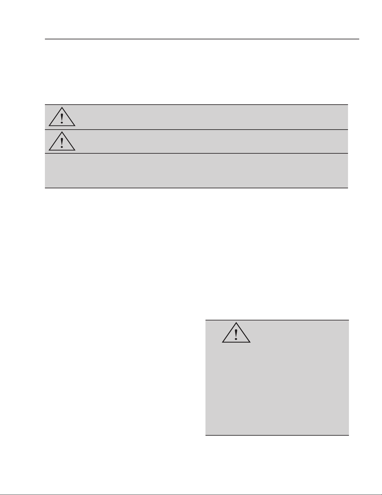
safeTy InsTruCTIOns - DefInITIOn Of Terms
reaD anD fOllOW THese InsTruCTIOns
saVe THese InsTruCTIOns
WARNING
CAUTION
indicates a potentially hazardous situation which, if not avoided, could
result in death or serious injury.
indicates a potentially hazardous situation which, if not avoided, may
result in minor or moderate injury.
used without the safety alert symbol indicates a potential situation which, if
NOTICE
not avoided, may result in an undesirable result or state, including property
damage.
1.1 HazarD-free use
This device left the factory in proper condition to be safely installed and operated in a hazard-free manner. The
notes and warnings in this document must be observed
by the user if this safe condition is to be maintained and
hazard-free operation of the device assured.
Take all necessary precautions to prevent damage
to the valve status monitor due to rough handling,
impact, or improper storage. Do not use abrasive
compounds to clean the actuator, or scrape metal
surfaces with any objects.
• Is trained or authorized to energize, de-energize,
ground, tag and lock electrical circuits and equipment
in accordance with established safety practices
• Is trained in the proper use and care of personal
protective equipment (PPE) in accordance with
established safety practices
• Is trained in rst aid
• In cases where the device is installed in a potentially
explosive (hazardous) location – is trained in the
operation, commissioning, operation and maintenance
of equipment in hazardous locations
WARNING
The control systems in which the valve status monitor is
installed must have proper safeguards to prevent injury
to personnel, or damage to equipment, should failure of
system components occur.
1.2 QualIfIeD PersOnnel
A qualied person in terms of this document is one who
is familiar with the installation, commissioning and operation of the device and who has appropriate qualications, such as:
• Is trained in the operation and maintenance of electric
equipment and systems in accordance with established safety practices
The valve status monitor must only be installed,
commissioned, and operated by qualied personnel.
The device generates large mechanical force during
normal operation.
All installation, commissioning, operation and
maintenance must be performed under strict
observation of all applicable codes, standards and
safety regulations.
Reference is specically made here to observe all
applicable safety regulations for actuators installed in
potentially explosive (hazardous) locations.
1
Page 4

BRAY Series 52 Valve Status Monitor
Operation and Maintenance Manual
CAT 3, S52 2N1ProxSensor
Valve Status Monitor
User Instructions. (EHSR 1.0.6)
specic to hazardous area installations
(reference European ATEX Directive 94/9/EC,
Annex II, 1.0.6.)
The following instructions apply to the Bray
International S52 2N1ProxSensor Valve Status
Monitors Part nos. 52100*-71114536 (*= 1, 2, 4,
6, 7, 8, and 9) covered by certicate number Sira
11ATEX4135X. Translations into other languages
are available on request.
1. The equipment may be used with ammable
gases and vapours with apparatus Gas Groups
IIA, IIB and IIC in Zone 2 locations, and Dust
Group IIIB in zone 22 locations.
2. The equipment Temperature Class is T4 for
gases and T102°C for dusts, and is only certied
for use in ambient temperatures in the range
-20°C to +70°C and should not be used outside
this range.
3. Installation shall be carried out in accordance
with the applicable code of practice by suitablytrained personnel.
4. Repair of this equipment shall be carried out in
accordance with the applicable code of practice.
5. The X sufx to the certicate number is to
indicate that there is a special condition for safe
use, which is regarding the potential build up of
static electricity and the precautions to be taken,
some of the sensors must be protected from
impact/ mechanical damage.
6. If the equipment is likely to come into contact
with aggressive substances, then it is the
responsibility of the user to take suitable
precautions that prevent it from being adversely
affected, thus ensuring that the type of protection
is not compromised.
Aggressive substances - e.g. acidic liquids or gases
that may attack metals, or solvents that may affect
polymeric materials.
S52 2N1ProxSensor Intrinsically
Safe Valve Status Monitor
User Instructions
specic to hazardous area installations
(reference European ATEX Directive 94/9/EC,
Annex II, 1.0.6.)
The following instructions apply to the Bray
International S52 2N1ProxSensor Valve Status
Monitor Part 521003-71114536 Intrinsically Safe
covered by certicate number Sira 11ATEX2134X.
Translations into other languages are available on
request.
1. The equipment may be used with ammable
gases and vapours with apparatus Gas Groups
IIA, IIB and IIC in Zone 0, 1 or 2 locations.
2. The equipment Temperature Class is T4 and is
only certied for use in ambient temperatures
in the range -20°C to +70°C and should not be
used outside this range.
3. Installation shall be carried out in accordance
with the applicable code of practice by suitablytrained personnel.
4. Repair of this equipment shall be carried out in
accordance with the applicable code of practice.
5. The X sufx to the certicate number is to
indicate that there is a special condition for safe
use, which is regarding the potential build up of
static electricity and the precautions to be taken.
6. If the equipment is likely to come into
contact with aggressive substances, then
it is the responsibility of the user to take
suitable precautions that prevent it from being
adversely affected, thus ensuring that the type
of protection is not compromised.
Aggressive substances - e.g. acidic liquids or gases
that may attack metals, or solvents that may affect
polymeric materials.
Suitable precautions - e.g. regular checks as part
of routine inspections or establishing from the
material’s data sheet that it is resistant to specic
chemicals.
Suitable precautions - e.g. regular checks as part
of routine inspections or establishing from the
material’s data sheet that it is resistant to specic
chemicals.
Copy of Certicate number Sira 11ATEX4135X
2
Copy of Certicate number Sira 11ATEX2134X
Page 5

BRAY Series 52 Valve Status Monitor
C E R T I F I C A T ION
Operation and Maintenance Manual
1 EC TYPE-EXAMINATION CERTIFICATE
2 Equipment intended for use in Potentially Explosive Atmospheres Directive 94/9/EC
3 Certificate Number: Sira 11ATEX2134X Issue: 0
4 Equipment: Series 52 2N1ProxSensor Valve Status Monitor
5 Applicant: Bray International
6 Address: 13333 Westland East Boulevard
7 This equipment and any acceptable variation thereto is specified in the schedule
the documents therein referred to.
8 Sira Certification Service, notified body number 0518 in accordance with Article 9 of Directive 94/9/EC
of 23 March 1994, certifies that this equipment has been found to comply with the Essential Health and
Safety Requirements relating to the design and construction of equipment intended for use in
potentially explosive atmospheres given in Annex II to the Directive.
The examination and test results are recorded in the confidential reports listed in Section 14.2.
9 Compliance with the Essentia
the schedule to this certificate, has been assured by compliance with the following documents:
EN 60079-0:2006 EN 60079-11:2007 EN 60079-26:2007 EN 61241-11:2006
EN 60079-0:2009
10 If the sign ‘X’ is placed after the certificate number, it indicates that the equipment is subject to special
conditions for safe use specified in the schedule to this certificate.
11 This EC type-examination certificate relates only to the design and construction
equipment. If applicable, further requirements of this Directive apply to the manufacture and supply of
this equipment.
12 The marking of the equipment shall include the following:
Houston
Texas, 77041
USA
to this certificate and
l Health and Safety Requirements, with the exception of those listed in
(used for guidance in respect of marking)
of the specified
Project Number 22753 D R Stubbings BA MIET
This certificate and its schedules may only be
reproduced in its entirety and without change.
Form 9400 Issue 2
II 1 G D
Ex ia IIC T4 Ga Ta = -20°C to +70°C
Ex iaD 20 T135°C Da
Certification Manager
Sira Certification Service
Page 1 of 2
Rake Lane, Eccleston, Chester, CH4 9JN, England
Tel: +44 (0) 1244 670900
Fax: +44 (0) 1244 681330
Email: info@siracertification.com
Web: www.siracertification.com
3
Page 6

BRAY Series 52 Valve Status Monitor
C E R T I F I C A T ION
Operation and Maintenance Manual
1 TYPE EXAMINATION CERTIFICATE
2 Equipment intended for use in Potentially Explosive Atmospheres Directive 94/9/EC
3 Certificate Number: Sira 11ATEX4135X Issue: 0
4 Equipment: Series 52 2N1ProxSensor Valve Status Monitors
5 Applicant: Bray International
6 Address: 13333 Westland East Boulevard
7 This equipment and any acceptable variation thereto are specified in the schedule to this certificate and
the documents therein
8 Sira Certification Service certifies that this equipment has been found to comply with the Essential
Health and Safety Requirements that relate to the design of Category 3 equipment, which is intended
for use in potentially explosive atmospheres. These Essential Health and Safety Requirements are given
in Annex II to European Union Directive 94/9/EC of 23 March 1994.
The examination and test results are recorded in the confidential reports listed in Section 14.2.
9 Compliance with the Essential Health and Safety Requirements, with the exception of those listed in the
schedule of this ce
EN 60079-0:2009 EN 60079-15:2010 EN 60079-31:2008
10 If the sign “X” is placed after the certificate number, it indicates that the equipment is subject to special
conditions for safe use specified in the schedule to this certificate.
11 This TYPE EXAMINATION CERTIFICATE relates only to the design of the specified equipment, and not
to specific items of equipment subsequently manufactured.
12 The marking of the equipment shall include the following:
Houston
Texas, 77041
USA
referred to.
rtificate, has been assessed by reference to:
Project Number 22753 D R Stubbings BA MIET
This certificate and its schedules may only be
reproduced in its entirety and without change.
Form 9402 Issue 2
4
II 3 G D
Ex nA IIC T4 Gc Ta = -20°C to +70°C
Ex tc IIIB T102°C Dc
Page 1 of 2
Certification Manager
Sira Certification Service
Rake Lane, Eccleston, Chester, CH4 9JN, England
Tel: +44 (0) 1244 670900
Fax: +44 (0) 1244 681330
Email: info@siracertification.com
Web: www.siracertification.com
Page 7

BRAY Series 52 Valve Status Monitor
Operation and Maintenance Manual
Introduction
Note: The following information is intended to assist individuals with the use and support of the
Bray S52 Valve Status Monitors.
The Series 52 Valve Status Monitor has been designed to provide valve position indication. The
2N1TM ProxSensor is available in several con-
gurations:
• DC Version 10-30VDC PNP (Sourcing)
• DC Version 10-30VDC NPN (Sinking)
• DC NAMUR Intrinsically Safe Version
(to be used with IS Barrier)
• AC Version 20-250VAC, 50-60Hz
• Fieldbus capable Versions
1. AS-i (Actuator Sensor Interface)
2. DeviceNet
3. PROFIBUS DP (Process Fieldbus
Decentralized Peripherals)
Each of these congurations will be covered in
more detail on the pages that follow. Additionally, examples of how to apply some of these products will be given.
All Bray S52 Valve Status Monitors utilize solid
state switches. Although the solid state switch
performs the same function as a conventional mechanical switch, there are differences in the way
solid state switches operate.
NOTICE
It is very important for the user to pay close
attention to the exact specications of their
sensor in order to avoid damaging the unit.
Solid state switches have current restrictions imposed by the semi conducting materials used to
form the sensor. These current limitations have to
be accounted for during setup. Unlike mechanical switches, which can normally handle several
amperes of current owing through them, solid
state switches are generally rated for half an ampere or less.
NOTICE
The Parameters of the S52 must be
compatible with the application
When working with the S52, several parameters
must be considered. A few of which (with signicant importance) are listed here: operating volt-
age, maximum switching current, output voltage
drop, and residual current. Using an S52 outside
of these parameter limits can cause damage to the
unit and void factory warranty.
Operating voltage is the amount of voltage necessary for the sensor to operate. The maximum
switching current is the largest amount of current that the sensor’s solid state electronics can
have owing through them in the On-State (when
the target is in proximity of the sensor). During
commissioning, it is up to the user to correctly apply the sensor to their control system in order to
limit the current owing through the device. This
is done through the use of a load; all the wiring
diagrams associated with the S52s specify where
this load needs to be placed in the circuit. Common control systems utilize a digital input card
to monitor devices like the S52; these cards have
loads (parameter usually referred to as “input impedance”) – it is the responsibility of the user to
ensure that this load is sufciently sized to limit
the current owing through the S52 below the
maximum switching current, yet above the OnState input current minimum of their monitoring
device. We will cover an example of this on page
14-15.
Output voltage drop is dened as the amount of
voltage that will drop across the solid state switch.
This voltage drop will often vary with the amount
of current owing through the sensor and the load.
5
Page 8

BRAY Series 52 Valve Status Monitor
Operation and Maintenance Manual
This drop in voltage becomes paramount when
connecting several valve status monitors in series,
each unit will have a voltage drop across it – adding each subsequent drop and subtracting from
the supply voltage yields the resulting voltage at
the end of the series connection. The user needs
to ensure that the supply voltage is large enough
so that the resulting voltage after all the drops is
above the min. operating voltage of the last S52 in
the series connection. Sensors located a great distance from the load require consideration as well,
as a general rule, every 1000 ft. of wire will have
a resistance of 10Ω (see electrical code references
for the resistance value of specic wire sizes), it is
important for the customer to ensure that the distance between the S52 and the control panel is not
long enough to cause the voltage drop to fall below the minimum operating voltage of the sensor.
Residual current is often referred to as leakage current. In the “Off” state (target is NOT in
proximity of the sensor) the sensor draws a small
amount of current in order to power the device’s
electronics. This is necessary for the device to
sense the target at any point in time when the supply voltage is applied. It is important that this
residual current is below the maximum Off-State
current rating of the control system.
Target Mounting
All congurations of the S52 are offered with two
types of targets; adjustable and non-adjustable.
Standard S52 (AC, DC, and DC Intrinsically Safe
units) utilize inductive proximity sensing technolo-
gy to provide valve position indication; the eldbus
capable versions utilize hall effect sensing technology to accomplish the same objective. When ap-
plying eldbus capable S52s, the same targets are
used; however, small magnets are located in the
small chambers behind the metal inserts on the
sides of the targets.
Adjustable Target Mounting
The adjustable versions are for customers that want the exibility to position their indication limits outside
of the standard 0 to 90°. The components that come in the adjustable target kit are displayed in Figure 1.
Figure 2 shows the components of the High Visibility Indicator Kit and the adjustable target kit.
Figure 1: Adjustable Target Kit. From
Left to Right: (1) S52 Mounting Screws,
(2) Base, (3) Middle Piece, (4) Top, (5)
Yellow Pointer w/ mounting screw
Figure 2: High visibility indicator with adjustable
target. Pictured from left to right:
(1) Indicator cover w/mounting screws, (2) indica-
tor w/mounting screw, and (3) adjustable target.
6
Page 9

BRAY Series 52 Valve Status Monitor
Operation and Maintenance Manual
The steps required to set up the adjustable target for your S52 2N1 Valve Status Monitor:
Step 1: Place the base on top of your pneumatic
actuator’s output pinion.
Step 3: Place the top piece so that the metal target
will be directly in front of the top switch (labeled
1) on the S52 when the actuator rotates to it’s opposite end of travel position. If you have a high
visibility indicator kit, jump to step 5 - otherwise
proceed to step 4.
Step 2: Place the middle piece on top of the base so
that the metal target is in front of where the bottom
switch (labeled 2) of the S52 will be located.
Step 4: Place the yellow pointer in your desired
orientation and tighten the mounting screw. Note:
Units assembled at the factory will have yellow
pointers in line with valve discs.
Step 5: Mount the high visibility beacon on top of
the target to display ‘Open’ and ‘Closed’ according
to your actuator/valve mounting orientation.
Step 6: Tighten the mounting screw to ensure that
your indicator and target are secured to the pinion
of the actuator. Note: damage to the indicator can
result from over tightening the screw.
7
Page 10

BRAY Series 52 Valve Status Monitor
Operation and Maintenance Manual
Step 7: Place the S52 on the actuator, aligning the holes in
the sensor with the mounting holes of the actuator. Insert the
cover over the indicator and align the mounting holes of the
cover with those of the sensor. Use the longer mounting bolts
supplied with your kit and tighten the cover and sensor to the
actuator.
Non-Adjustable Target Mounting
The S52 Valve Status Monitor is offered with a non-adjustable
target. The non-adjustable target is a one piece puck style target
with metal inserts offset by 90°. The yellow pointer however is
adjustable and can be positioned however you require; when the
unit is mounted at the factory the pointer will be in line with the
valve disc. All components of the non-adjustable kit are shown below in Figure 3. The procedure for mount-
ing the non-adjustable target is described on the next page. Note: when conguring this target with your
input monitoring device pay close attention to metal insert position versus sensor position as your actuator
rotates from open to close.
Figure 3: Non-Adjustable Target with pointer.
Figure 4: Non-adjustable Target mounting
Mounting of the non-adjustable target:
Insert the target on the pinion of the pneumatic
actuator. Based on what position your pinion/actuator is in, one of the metal inserts of the target
will be directly in front of switch ‘1’ or switch
‘2’ on your sensor. When your quarter turn actuator rotates 90° to its opposite travel limit, the
other metal insert of the target will be directly
in front of switch ‘2’ or switch ‘1’, respectively.
Position your actuator to yield your desired indication results.
8
Page 11

BRAY Series 52 Valve Status Monitor
Operation and Maintenance Manual
The Standard S52 (non eldbus capable versions) are offered with two types of connections; the DC versions are offered with a 4-pin M12 connection, and the AC versions are offered with a 5-pin 7/8” con-
nection. Both types are pictured below:
4-pin M12 Connector 5-pin 7/8” Connector
Figure 5: Standard S52 Connectors
The following pages cover each of the congurations of the S52 in more detail.
DC Version 10-30VDC PNP (Sourcing)
Specications:
Operating Voltage 10 to 30VDC
Target Type Metallic
Electrical Conguration DC - PNP
Maximum Switching
Current 200mA
Output Voltage Drop < 2VDC
Residual Current (Off
State Current) 20μA
+
10 to 30 Vdc
-
LOAD 2
LOAD 1
PIN 1
PIN 2
PIN 4
PIN 3
S2
PNP
WIRING DIAGRAM
3
4
2
1
KEY
M12 X1
CONNECTOR
PINOUT
DIAGRAM
S1
PNP
9
Page 12

BRAY Series 52 Valve Status Monitor
!
Operation and Maintenance Manual
DC Version 10-30VDC NPN (Sinking)
Specications:
Operating Voltage 10 to 30VDC
Target Type Metallic
Electrical Conguration DC - NPN
Maximum Switching Current 200mA
Output Voltage Drop < 2VDC
Residual Current (Off State Current) 20μA
+
10 to 30 Vdc
-
LOAD 2
LOAD 1
PIN 1
PIN 2
PIN 4
PIN 3
S2
PNP
WIRING DIAGRAM
3
4
2
1
KEY
M12 X1
CONNECTOR
PINOUT
DIAGRAM
S1
PNP
I.S. S52 must be used in conjunction with I.S. barrier. Installation and wiring should
WARNING
be carried out by trained personnel who will ensure that the work complies with local
standards & NEC practices
Any approved Intrisically Safe
apparatus with Entity Concept parameters as follows:
Voc or Vt ≤ 15V
Isc or It ≤ 53mA
Ca = Ccable + 220nF
La > Lcable + 280 uH
Any approved Intrisically Safe
apparatus with Entity Concept parameters as follows:
Voc or Vt ≤ 15V
Isc or It ≤ 53mA
Ca = Ccable + 220nF
La > Lcable + 280 uH
WIRING DIAGRAM
DC Intrinsically Safe Version
+
PIN 1
_
PIN 4
+
PIN 2
_
PIN 3
Specifications:
Operating Voltage 7 to 12VDC
Target Type Metallic
Electrical Conguration NAMUR
S1
S2
10
Page 13

WARNING
!
BRAY Series 52 Valve Status Monitor
Operation and Maintenance Manual
AC Version 20-250VAC, 50-60Hz
I.S. S52 must be used in conjunction with I.S. barrier. Installation and
wiring should be carried out by trained personnel who will ensure that the work
complies with local standards & NEC practices
3
KEY
2
1
NOTE:
WIRES NOT USED SHOULD BE
COILED AND TAPED FOR
PROTECTION
4
5
7/8’’ 16 UN CONNECTOR
PINOUT DIAGRAM
NEUTRAL
20 to 250 Vac
LIVE
NOT USED
LOAD 2
LOAD 1
PIN 5
PIN 4
PIN 2
PIN 3
PIN 1
WIRING DIAGRAM
Specications:
Operating Voltage 20-250 VAC
Target Type Metallic
Electrical Conguration AC
Maximum Switching Current 500mA
Output Voltage Drop < 5VAC
Residual Current (Off State
Current) < 1mA
S2
S1
Bray P/N: 52-1004-12624-536 (Kit) includes:
- 52-1004-71114-536 (S52)
- 52-1000-14811-533 (target & std. indicator)
Drawing: ES11A-0544
S63 Solenoid, Bray P/N:
PLC with Digital
63-0250-21520-536
AC Input Module
Y Cord, Bray P/N: 60-0250-23661-536
Drawing # : ES11A-0559
11
Page 14

BRAY Series 52 Valve Status Monitor
Operation and Maintenance Manual
AS-i (Actuator Sensor Interface) Version with
M12 Quick Connector
S1
S2
Specications:
Operating Voltage 30.5 VDC by AS-i Network
Target Type Magnetic
Electrical Conguration AS-i Spec. 3.2 (1), (2)
Maximum Switching Current 100mA
Consumption Current < 25mA
Addressing 0 to 31A or B
Data Bits Bit 0: Sensor 1
Bit 1: Sensor 2
Bit 2: Output to Solenoid
(1) Hardware AS-i Version 3.0 - congured as AS-i Version 2.1
(2) Full backwards compatibility is maintained with earlier
AS-i networks and products
2
4
1
3
SOL -
SOL +
GND GN/YE
NC
NC
YE
RD
WIRING DIAGRAM
3
4
2
1
KEY
M12 X1
CONNECTOR
PINOUT
DIAGRAM
BN
BU
+
_
AS - i
AS-i Controller and
AS-i 24VDC Power Supply
12
AS-i S52, Bray P/Ns:
52-1005-12624-536 (Kit) includes:
- 52-1005-71114-536 (S52)
- 52-1000-14821-533 (target)
52-1000-14805-533 (high visibility
indicator)
AS-i bus
Page 15

BRAY Series 52 Valve Status Monitor
Operation and Maintenance Manual
DeviceNet Version
S1
S2
Specications:
Operating Voltage 24VDC by DN Network
Target Type Magnetic
Electrical Conguration DeviceNet
Maximum Switching Current 100mA
Consumption Current < 20mA
Output Voltage Drop < 2.5VDC
Addressing 0 to 63 software congured
Data Bits Input Bit 0: Sensor 1
Input Bit 1: Sensor 2
Output Bit 0: Solenoid
2
4
5
3
1
SOL -
SOL +
GND GN/YE
BARE
YE
RD
WIRING DIAGRAM
3
4
5
KEY
PINOUT DIAGRAM
RD
WH
BU
BK
V+
CNH
CNL
V-
GND
2
1
DeviceNet S52, Bray P/Ns:
52-1007-12624-536 (kit) includes:
- 52-1007-71114-536 (S52)
- 52-1000-14821-536 (target)
High Visibility Indicator,
Bray P/N: 52-1000-14805-533
PLC with DeviceNet
Scanner
13
Page 16

BRAY Series 52 Valve Status Monitor
OUT
IN
8
9
0
1
2
3
4
5
6
7
8
9
0
1
2
3
4
5
6
7
V -
V +
A
B
TERRE
X 10
X 1
SOL -
SOL +
NC
U = 24 V CC - IL = 50 mA
SÉLECTION
D’ADRESSE
RACCORDEMENTS
SUR BORNIER
Operation and Maintenance Manual
PROFIBUS DP Version
V -
(WH)
A
(YE)
V A
S1
S2
GND
B
V +
SOL -
SOL +
NC
YE
RD
GND
B
V +
V A
GND
B
V +
(GN)
(BR)
(WH)
(YE)
(GN)
(BR)
SCHÉMA ÉLECTRIQUE
Specications:
Operating Voltage 24VDC by Probus DP
Target Type Magnetic
Electrical Conguration Probus DP
Maximum Switching
Current 100mA
Consumption Current < 30mA
Output Voltage Drop < 2.5VDC
Addressing 0 to 63 software
congured
Data Bits Input Bit 0: Sensor 1
Input Bit 1: Sensor 2
Output Bit 0: Solenoid
Step 1: Purchase several
PROFIBUS DP S52s from
your local Bray Distributor
14
Step 2: Separate the
connection module from the
sensor module by loosening
the two fastening screws.
Step 3: Take an inventory of all components of the PROFIBUS DP S52 to
ensure that you have all the necessary
parts of the module. Clockwise from
the top left on the image above, you
should have th following: (a) connection module, (b) PG connectors, (c)
sensor module, (d) connection plate,
(e) terminal connectors.
Page 17

BRAY Series 52 Valve Status Monitor
Operation and Maintenance Manual
Step 4: Use the adjustment
knobs to set your device’s
network address.
Step 7: Place the connection
plate on the connection module
and tighten the fastening screws.
Step 5: Insert your solenoid cable
and your PROFIBUS DP & BUS
power cable through the cable
glands of the connection module.
Terminate the wires into the labeled connectors.
Step 8: Align the connection module to the sensor
module and tighten the fastening screws. Your sensor
is now ready to be mounted on your actuator.
Step 6: Heat shrink the terminations and pull the excess cable back
through the cable glands, aligning
the connectors with the chambers
of the connection module.
PLC with Probus
DP Scanner
Probus DP S52, Bray P/Ns:
52-1008-12624-536 (kit) includes:
- 52-1008-71114-536 (S52)
- 52-1000-14821-533 (target)
15
Page 18

BRAY Series 52 Valve Status Monitor
Operation and Maintenance Manual
Application Example #1 (DC PNP S52)
PLC with Digital
DC Input Module
DC PNP S52, Bray P/Ns:
52-1001-12624-536 (kit) includes:
- 52-1001-71114-536 (S52)
- 52-1000-14811-533 (adjustable target)
52-1000-14805-533 (high visibility indicator.)
Customer has an Allen Bradley CompactLogix 1769 PLC platform with DC Input Module Model #
1769-IQ6XOW4. In order for you to determine if the Bray S52 2N1 DC Prox Sensor is compatible with
this device, reference the specications of each device. Using the manufacturer’s website, you should
be able to nd a manual for your customers DCS or PLC. In this documentation, you can do a search for
the input module in question. Below are some important specications from Allen Bradley’s literature
on this specic card.
Model #: 1769-IQ6XOW4
Voltage Input Type 24V dc, sinking or sourcing
Voltage, On-state Input, Min. 10V dc
Voltage, On-state Input, Max. 30V dc @ °C (86 °F)
26.4V dc @ 60 °C (140 °F)
Number of Inputs 6
Voltage, Off-State Input, Max. 5V dc
Current, Off-State Input, Max. 1.5 mA
Current, On-Stae Input, Min. 2 mA
Input Impedance, Nom. 3 KΏ
From this information, and the DC PNP S52 specications on page 7, you should be able to determine
that these two devices are compatible.
• The operating voltage of the DC S52 (specied as: 10-30VDC) is within the acceptable On-State Input
Voltage Min. and Max. range of the Input Module (specied as: 10VDC to 30 VDC @86°F/26.4Vdc
@140°F).
16
Page 19

BRAY Series 52 Valve Status Monitor
Operation and Maintenance Manual
• The residual Off-state Current of the DC S52 (specied as: 20 μA) is below the Off-State Current Max.
of the Input Card (specied as: 1.5mA). Note: this means that the leakage current of the S52 will not
cause false readings.
• The Nominal Impedance of the Input Card (specied as: 3kΩ) is sufcient enough to limit the current
owing through the proximity switch below its Max. Switching Current (specied as: 200mA).
Ohm’s Law: V = IR (V = Voltage, I = Current, R = Resistance*)
24VDC = I x 3 KΩ
24/3000 = .008 A or 8 mA
This value is the amount of current that will ow through the S52 in the On-State (when the target is
in proximity of the sensor). This value, 8 mA, is below the Max. Switching Current of the S52 (current exceeding 200mA can damage the device) and above the Min. On-State Input Current of the input
module (specied as: 2mA). *Note: Resistance in this case is referred to as Input Impedance
Once you have determined the compatibility of the two devices; you can wire the two devices together
using their appropriate wiring diagrams. The diagram in Figure 5 below shows you how to do this correctly.
Note: Each proximity switch in the S52 will require a separate input into the PLC card; thus, (1) S52 will
utilize (2) inputs into the PLC Input Module. One input for ‘Valve Open’ indication and one for ‘Valve
Close’ indication. Because this specic input module only has 6 inputs, three S52s can be wired into this
device. The number of necessary modules grows quite rapidly when you have several devices in use; this
is why eldbus capable versions can be so cost effective, for more information please see the eldbus ap-
plication example.
FIELD WIRING TO PLC
AND 24 VDC SUPPLY
+
24 Vdc
DC
COM
LOAD 2
LOAD 1
IN 0
IN 1
-
S52 VALVE STATUS
MONITOR
PIN 1
S2
PNP
PIN 2
S1
PNP
PIN 4
PIN 3
WIRING DIAGRAM
Figure 5: Wiring diagram showing how to wire a DC PNP S52 to an
Allen Bradley Model # 1769-IQ6XOW4 DC Input Module.
17
Page 20

BRAY Series 52 Valve Status Monitor
Operation and Maintenance Manual
Application Example #2 (AS-i S52)
Customer has an AS-i (Actuator Sensor Interface) controller with an AS-i approved 24VDC power sup-
ply. Once your customer has the conguration software (usually provided with the controller) they can
scan the bus and congure any AS-i device connected. Up to 62 devices can be connected to one con-
troller (V2.1 or 3), in applications requiring several valve status monitors, cost is greatly reduced when
only one single module can control 62 devices versus having to purchase a PLC input module for every
three to four S52s that you have.
1) Bray S52 is connected to the AS-i
BUS and is located at address 12.
2) By selecting the device at address
12, a conguration window allows
you to modify the device address,
check input state, and test the output.
3) Input 1 is shown in the ‘On’ State, Input 0
is ‘Off’, and the Output to the solenoid is not
energized.
AS-i Controller and
AS-i 24VDC Power Supply
AS-i slave (1 of 62), Bray S52 P/Ns:
52-1005-12624-536 (kit) includes:
- 52-1005-71114-536 (S52)
- 52-1000-14821-533 (target)
52-1000-14805-533 (indicator)
AS-i bus
18
Page 21

CONTROLS
R
A Division of BRAY INTERNATIONAL, Inc.
13333 Westland East Blvd. Houston, Texas 77041
281/894-5454 FAX 281/894-9499 www.bray.com
Bray® is a registered trademark of BRAY INTERNATIONAL, Inc.
© 2011 Bray International. All rights reserved. OM-52-001 07-2011
 Loading...