

Page 1

BTI
Bravo Tech, Inc.
Users Manual
FCC ID: O2H LPA800-200-1
1
Page 2

BTI
Bravo Tech, Inc.
LPA800 Operating Manual
Table of Contents
Section Page Number
1.General
1.1-Introduction ………………………………………………………………………… 3
1.2-General Description………………………………………………………………… 3-4
1.3-Functional and Physical Specifications……………………………………………… 4
1.4-Equipment Changes………………………………………………………………….. 4
2. Inst allation
2.1-Introduction………………………………………………………………………….. 5
2.2-Electrical Service Recommendations………………………………………………... 5
2.3-Unpacking and Inspection………………………………………………………….... 5
2.4-Installation Instructions……………………………………………………………... 5
2.5-Amplifier Status……………………………………………………………………... 6
3.Operating Instructions
3.1-Introduction………………………………………………………………………….. 7
3.2-Connections…………………………………………………………………………... 7-9
3.3-Initial startup and Operating Procedure……………………………………………… 10
4.Principles of Operation
4.1-Introduction………………………………………………………………………….. 11
4.2-RF Input signal…………………………………………………………………….… 11
4.3-RF Output Load……………………………………………………………………… 11
4.4-Amplifier Functional Description………………………………………………….. 11-12
4.5-Amplifier Monitoring……………………………………………………………….. 12
4.6-Amplifier Cooling…………………………………………………………………… 129
5.Maintenance
6.Table
Table 1 – Functional and Physical Specifications
………………………………………………………………………………………………………. 4
……………………………………………………………………………..…………….. 13
FCC ID: O2H LPA800-200-1
2
Page 3

BTI
SECTION 1
Bravo Tech, Inc.
GENERAL
1-1. INTRODUCTION.
Congratulation on purchasi ng Bravo Tech’s advanced linear power amplifier. Our goal is to
satisfy you with our RF technology expertise, offering the best product with unsurpass e d quality,
performance and at the best price. In fact, a strong background in wireless communication
technologies enables Bravo Tech to provide highly integrated products wit h the most advanced
features in the industry. Our commitment to quality and product excellence makes Bravo Tec h a
strong contender in the industry.
Bravo Tech designs, manufactures, and markets the most advanced Linear Power Amplifiers for
use in wireless communication systems. Our Linear Power Amplifiers are designed with the most
advanced RF and digital control technology.
Our focus on high-end power amplifiers at affordable price res u lts in total commit ment to
offering state of the art products to meet the growing needs of today‘s exploding wireless
communication ma rket. We consider "value" a requirement in every facet of a product, not just a
feature. When comparing Power Amplifiers, consider all the essential factors in your decision.
Price and performance c haracteris tic s such as distortion specifica tions, fle xibility , reliability a nd
design parameters are critica l. And not least of all the warra nty- will t he manufacturer sta nd
behind thei r products ? Bravo Tech will consistently outpace the competitio n in every category.
This manual contains information and procedures for installation, operation, and maintenance of
the LPA800 Series multic ha nnel feed-forward linear power amplifier system. The manual is
organized into five sections as follows:
Section 1. General Des c ription
Section 2. Installation
Section 3. Opera ting Instructions
Section 4. Principles of Operation
Section 5. Maintena nce
1-2. GENERAL DESCRIPTION
The LPA800 Series
trunk ing systems, featuring bandwidth up to 20 MHz and output power up to 200W per system.
Our Power Amplifiers are designed with our advanced RF and digital control technology. T hey
provide unsurpass e d p ower, linearity, efficiency, a nd sys tem flexibility in trunking, ce llula r, and
wireless loca l loo p systems. T he intelligent digital control sys te m constantly fine-tunes the
amplifiers to ensure optimum operation over a wide variety of electrical and environmental
conditions. T he amplifiers can be fed up to 16 channels and meet all FC C require ments.
The system is designed to provide trouble free operation with minimum maintenance. T he LEDbased operational status and fault indicators help minimize downtime. T he turn-on and tur n-off
sequences of voltages are fully automatic, as is overload protection, making the amplifier
multichannel feed-forward linear power amplifier is specially designed for
FCC ID: O2H LPA800-200-1
3
Page 4

BTI
virtually impervious to failures caused by system problems.
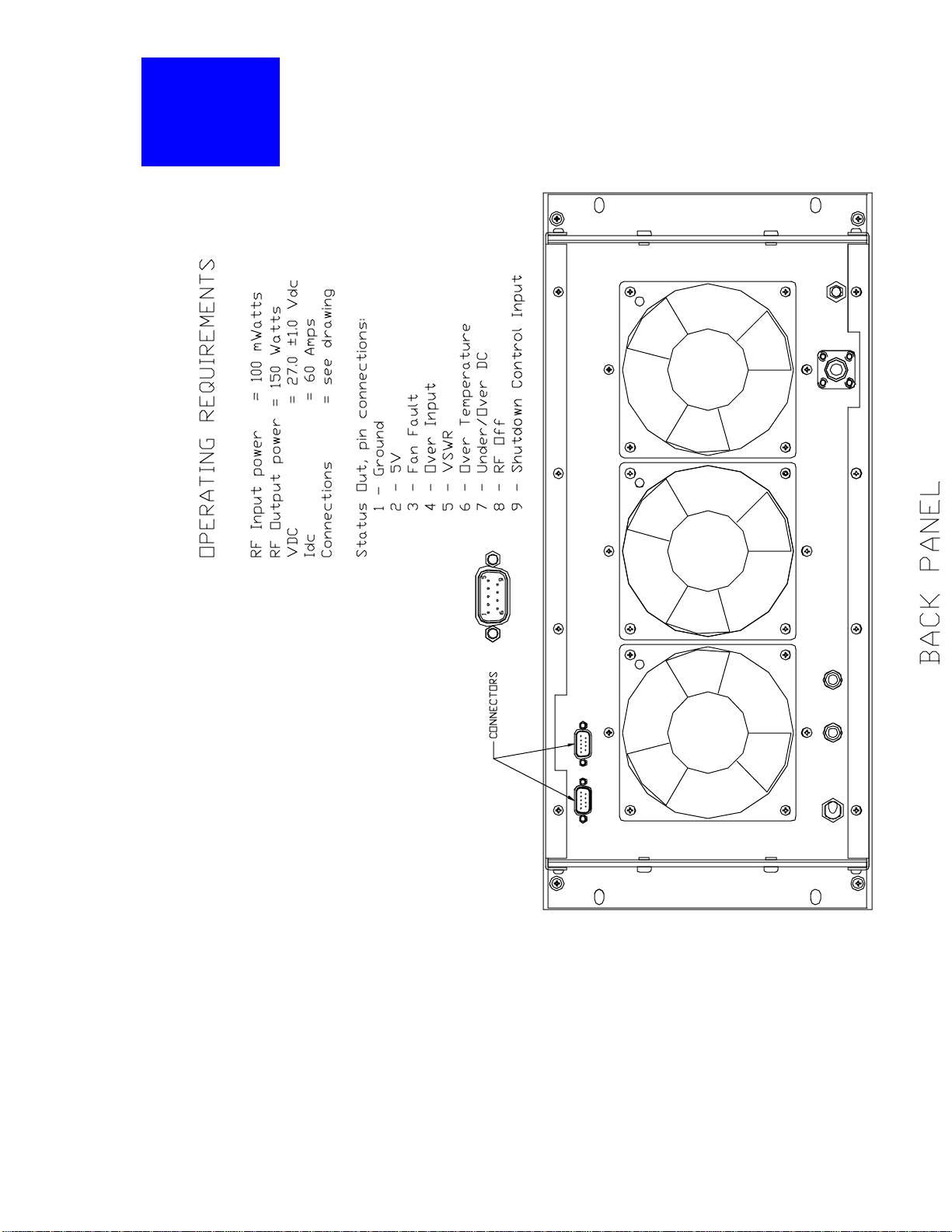
RF I/O and D.C. Power are connected to the rear panel of the amplifier. The rear panel also has
the serial port connectors that interface with the host control system. The system status connector
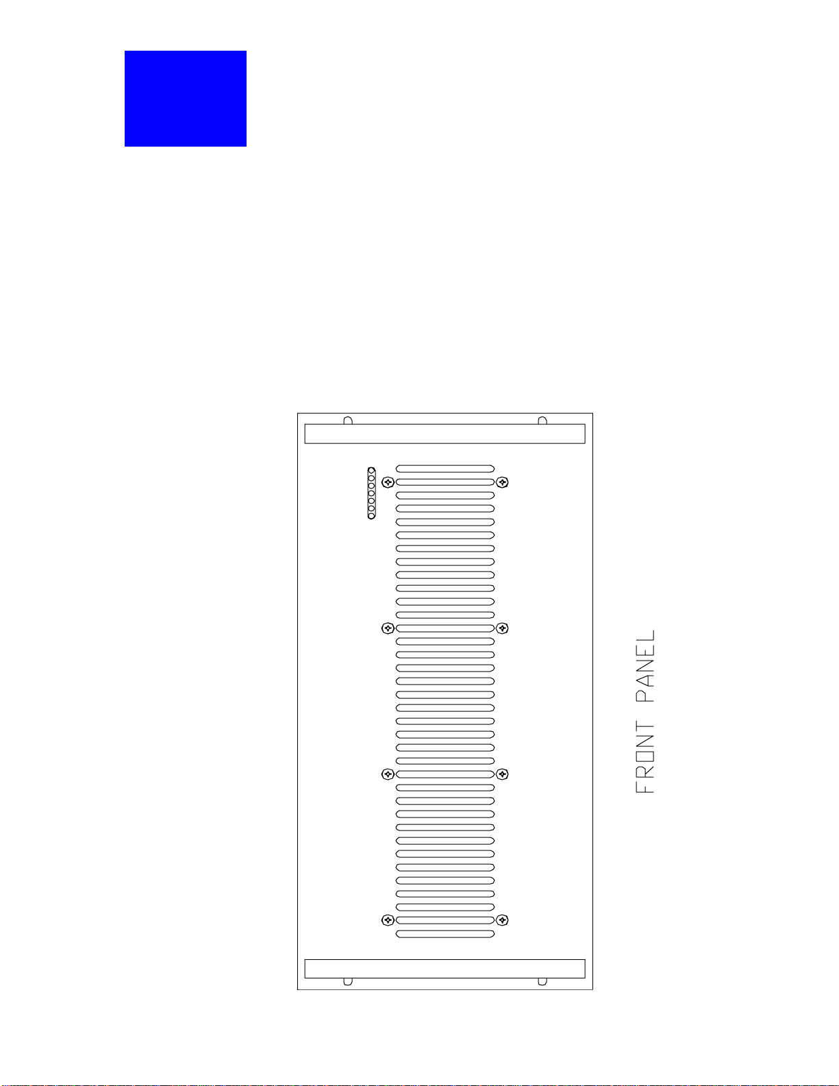
allows the host system to monitor performance of the amplifier. The fro nt panel of the amplifier
equipped with fault indicators. D.C. power for the amplifier system is +27 Vdc. C ooling for the
amplifier is provided by three fans mounted on the rear of the system. The fans draw outside air
through the front of and exhaust hot air through the rear of the rack.
Bravo Tech, Inc.
1-3. FUNC TIONAL AND PH YS ICAL SP ECIF IC A TIONS
Functional and physical s p ec ifica tions for the amplifier system are listed in Table 1.
PARAMETER SPECIFICATIONS
Frequency Range 850 - 870 MHz
Output Power 100-200 W Average
Peak Power Capacity 1600 W
IMD Meet FCC Requirements
RF Gain 35 dB
RF Gain Variation Over Frequency Band +/- 0.5 dB over the whole frequency band
RF Gain Variation Over Temperature +/- 0.7 dB (Max.)
Input / Output VSWR <2 : 1
Output Protection Isolator
Harmonic & Sprurious Emissions Meet FCC Requirements
DC Power Voltage Current Consumption 27V +/- 1.0 VDC 65A max @ 27VDC
Operation Temperature 0 To + 55C
Physical Dimensions 19" Rack Standard
Over Power Output Alarm
High Temperature Alarm and Shut-Down
Output VSWR Alarm @ 3: 1
Table 1 – Functional and physical specifications f or the amplif ier systems
@95C +/- 6 on the case of power transistor and recovery @
85C +/- 6
1-4 EQUIPMENT CHANGES
Bravo Tech reserves the right to make any changes to the equipment without notice, including but
not necess arily limited to component subs titution and circuit ry cha nges.
FCC ID: O2H LPA800-200-1
4
Page 5

BTI
SECTION 2
Bravo Tech, Inc.
INSTALLATION
2-1. INTRODUCTION
This section contains installation recommendations for the LPA800 amplifier. Please read the
material in this section prior to installatio n of the amplifier into a sys te m.
2-2. ELECTRICAL SERVICE RECOMMENDATIONS
Bravo Tech recommends that proper AC line conditioning and surge suppression is provided on
the primary AC input to the +27 Vdc power source. All electrical service should be installed in
accordance with any applicable government or local regulations (codes) and good engineering
practice.
2-3. UNPACKING AND INSPECTION
This equipment has been tested and calibrated at the factory. Only in the event of severe shocks
or other mistreat ment should any substantial readjustment be required. Check the outside of the
shipping container for instru c ti ons re garding u npa c k in g. C a re fu l ly ope n the co ntainer and re move
the amplifier module. Retain all packing material that can be reassembled in the event the unit
must be returned to the factory.
CAUTION
Exe rcis e c are in handling equipment duri ng inspection to prevent da mage.
!
Visually inspect the amplifier for damage that may have occurred during shipme nt.
!
Check for evidence of water damage, bent or warped chassis, loose screws or nuts, or
!
extraneous packing material in connectors or fans.
Inspect all connectors for bent connector pins. If the equipment is damaged, a claim
!
should be filed with the carrier once the extent of any damage is assessed. We cannot
stress too strongly the importance of IMMEDIATE careful inspectio n of the equipment
and the subse quent
IMMEDIATE filing of the necessary claims against the carrier if necessary. If possible,
!
inspect the equipment in the presence of the delivery person. If the equipment is
damaged, the carrier is your first area of recourse. If the equipment is damaged and must
be returned to the factory, please contact Bravo Tech for a return authorization. Bravo
Tech may not accept returns without a return authorization. Claims for loss or damage
may not be withheld from any payment to Bravo Tech, nor may any payment due be
withheld pending the outcome thereof.
2-4. INSTALLATION INSTRUCTIONS
To install the amplifier proceed as follows:
1. Install ampl ifier in equipment rack, and secure in place with four screws
2. Connect load cable to RF OUT connector on rear of amplifier.
3. Connect transceiver or exciter input to RF IN on rear of amplifier.
4. Connect +27 Vdc and GROUND to appropriate terminals on the amplifier rear panel.
5. Connect statas port on rear panel (if applicable).
FCC ID: O2H LPA800-200-1
5
Page 6

BTI
6. Check your work before applying DC voltage to the amplifier. Make certain all
connections are tight and correct.
7. Measure primary DC input voltage. DC input voltage should be +26-28 Vdc. If t he DC
input volta ge is above or below the limits, call and consult Bravo Tech before you apply
power to your amplifier.
2-5. AMPLIFIER STATUS
The amplifier has a remote alarm connector that is used by the host system to monitor the
amplifier. The status connections are made through a 9-pin D-Sub male connector and are listed
and described in
Figure 1 .
Bravo Tech, Inc.
FCC ID: O2H LPA800-200-1
6
Page 7

BTI
SECTION 3
OP ERATING INS TRUC TIO NS
3-1. INTRODUCTION.
This section contains operating instructions for the LPA800. Series Amplifier System.
3-2. Connections
LPA800 Input/Output Connectors (Rear Panel)
NUMBER NAME FUNCTION
1 +27V Input and RTN Input terminals for primary DC source
voltage
2 Jl 9-pin, male type D-SUB connector. Fault and control signals to
host
Bravo Tech, Inc.
system for each of the plug-in amplifier modules. Refer to
Figure 1 fo r a descripti on of the si gnals
3 J2 9-pin, female type D-SUB serial connector.
4 RF IN Type SMA female bulkhead connector.
5 RF OUT Type N female bulkhe ad c onnector.
FCC ID: O2H LPA800-200-1
7
Page 8
BTI
Bravo Tech, Inc.
RF INRF INRF IN
RF OUTRF OUTRF OUT
-
DC INDC INDC IN
SERIAL
STATUS OUT
+
OFF
POWER
ON
Figure 1 -
FCC ID: O2H LPA800-200-1
8
Page 9
BTI
LPA800 STATUS INDICATORS (Front Panel)
Bravo Tech, Inc.
NUMBER NAME FUNCTION
1 POWER ON Indicator Green Led. When lit, indicates that +27 Vdc is
2
3
4
5
6
7
OVER TEMP Red Led indicates o ve r temperature conditio ns
DC VOLTAGE Red Led indicates under or over voltage
FAN FAULT Red Led indicates fan fault conditio ns
OVER INPUT Red Led indicates ov er input power conditions
VSWR Red Led indicates bad antenna connections
RF OFF Red Led indicates RF power is turned off by
RF OFF
VSWR
OVER INPUT
FAN FA ULT
DC VOLTAG E
OVER TEMP
POWER ON
applied to the amplifier module.
conditions
system controller
FCC ID: O2H LPA800-200-1
Multi-Carrier Linear Power Amplifier
Figure 2 -
9
Page 10

BTI
3-3. INITIAL START-UP AND OPERATING PROCEDURES
Double check to ens ure that all input and output cables are properly connec ted.
WARNING
Before applying power, make sure that the input and output of the amplifier are properly
termi nated at 50 ohms. Do not operate the amplifier without a load attached. Refer to Table1 for
input power require ments. Excess ive input power may dama ge the amplifier
NOTE
The output coaxial cable between the amplifier and the antenna must be 50 Ohm coaxial
!
cable. Use of any other cable, will distort the output
Turn on supply that provides +26-28 Vdc to the amplifier system. Visually check the
!
amplifier as it is turned on, and verify that the DC ON indicator (gree n) comes on.
Bravo Tech, Inc.
As the LPA800 is controlled by an internal microprocessor-based optimization loop , the
!
specified linearity performance may not be obtained until several minutes after initial
turn-on.
FCC ID: O2H LPA800-200-1
10
Page 11

BTI
SECTION 4
Bravo Tech, Inc.
PRINCIPLES OF OPERATION
4-1. INTRODUCTION
This section contains a functional description of the LPA800 Series linear amplifier.
4-2. RF INPUT SIGNAL
The maximum i nput power for all carrier frequencies s hould not
exceed the limits specified in table 1. The input VS WR should be 2:1 maximum (or better).
4-3. RF OUTPUT LOAD
The load impedance should be as good as possible (1.5:1 or better) in the working band for good
power transfer to the load.
4-4. AMPLIFIER FUNCTIONAL DESCRIPTION
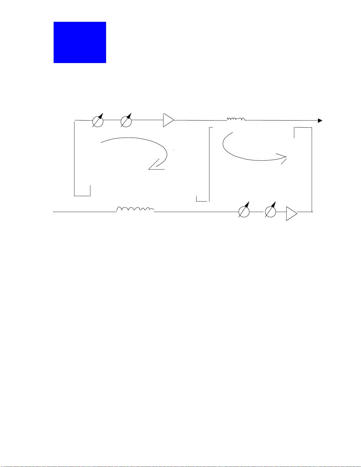
The amplifier is designed based on the feed-forward technique. The input RF carriers are
split into two paths at the coupler 1. One path is to the 1 loop delay line and the other
path is to the main amplifier path. The carriers’ are amplified by the main output stage
where distortion signal components are generated. The amplified signals, carriers plus
distortions, are fed into the second loop delay line while very small part of the output
signals are coupled by coupler 2 into the coupler 3, where the carrier components of the
coupled signals are cancelled with the pure input carriers at the coupler 3, resulting in
error signals. The phase-1 and attenuator-1 are adjusted to ensure the carrier cancellation
at the coupler 3 so that only error signals are fed into the second loop and amplified by
the error amplifier, which is a linear relatively low power amplifier. The phase and
amplitude of the amplified error signals are adjusted by phase-2 and attenuator_2,
respectively, so that they are cancelled with the error signals from the second loop delay
line at the coupler 4. After the cancellation, the output signals will be cleaned up so that
the amplifier can meet the FCC requirements.
FCC ID: O2H LPA800-200-1
11
Page 12
BTI
P
D
D
A
M
I
P
A
E
L
Bravo Tech, Inc.
nput
h 1
Coupler 1
tt 1
Loop 1
elay 1
ain Amp
Coupler 3
Figu re 3 – Loop Feed Forward
elay 2
Coupler 2
h 2
oop 2
Coupler 4
tt 2
Output
rror Amp
4-5. AMPLIFIER MONITORING
The microprocessor control allows the amplifier to protect itself agains t external occurrences . In
routine operation, all nor mal variations are a utomatically c ompe nsate d for. When large variations
occur the modules generate alarm outputs. The alarms are displayed on the fro nt panel indicator
and output via a connector on the rear of the rack for remote monitoring. Faults and alarms are
summarized in Figure 1.
4-6. AMPLIFIER MODULE COOLING
Three fans are used for forced air cooling .The fans are located on the rear of the amplifier and
exhaust hot air out the back of the module.
FCC ID: O2H LPA800-200-1
12
Page 13

BTI
SECTION 5
Bravo Tech, Inc.
MAINTENANCE
The LPA800 a mplifier co nta ins no user-serviceable parts. T here is no maintena nce that can be
performed by the user other than ensuring that the external connections to the amplifier are sound.
Breaking the s eals around the outside of the unit will render the warra nty null and void. If your
LPA800 amplifier requires any servicing, or fails to perform to specifications in any way, please
contact factory for RMA number and ship i n the original packing box to:
Bravo Tech Inc.
4260 Cerritos Ave.
Los Alamitos, CA 90720
Phone: 714-952-8324
Fax: 714-952-0107
FCC ID: O2H LPA800-200-1
13
 Loading...