

Page 1
BR50•10 Technical Manual
CHARACTERISTICS
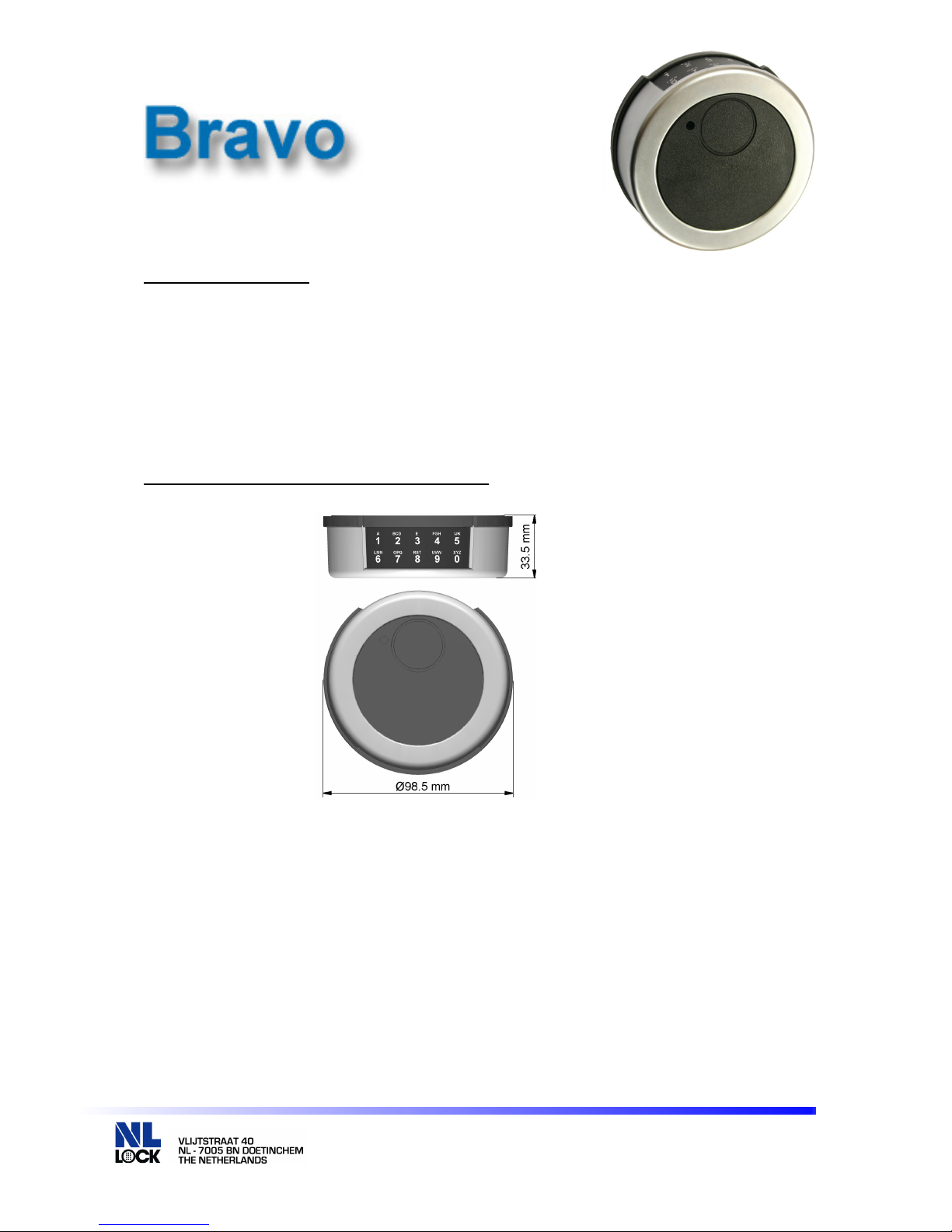
The Bravo is a top reading electronic entry unit that provides easy operation for
smaller home safes as well as providing spy protection. The numbers can only be
read up close by the operator. The code numbers cannot be “spied on” from the
distance. The Entry Unit features a terminal for an electronic key. The integrated
battery compartment in the bottom of the Bravo entry unit opens by moving a slider.
Cable length is approximately 30 cm. The Bravo entry can be mounted as stationary
or turnable model.
DIMENSIONS / MOUNTING INSTRUCTION
The Terminal for the electronic key (Dallas Key) is located in the front next to the light
signal. In case the terminal is not required, it should be covered with the provided
round black label.
BR50•10 Technical Manual 090729
© 2008 Lock Technology BV
Page 1 of 3
Page 2
1 2
3
5
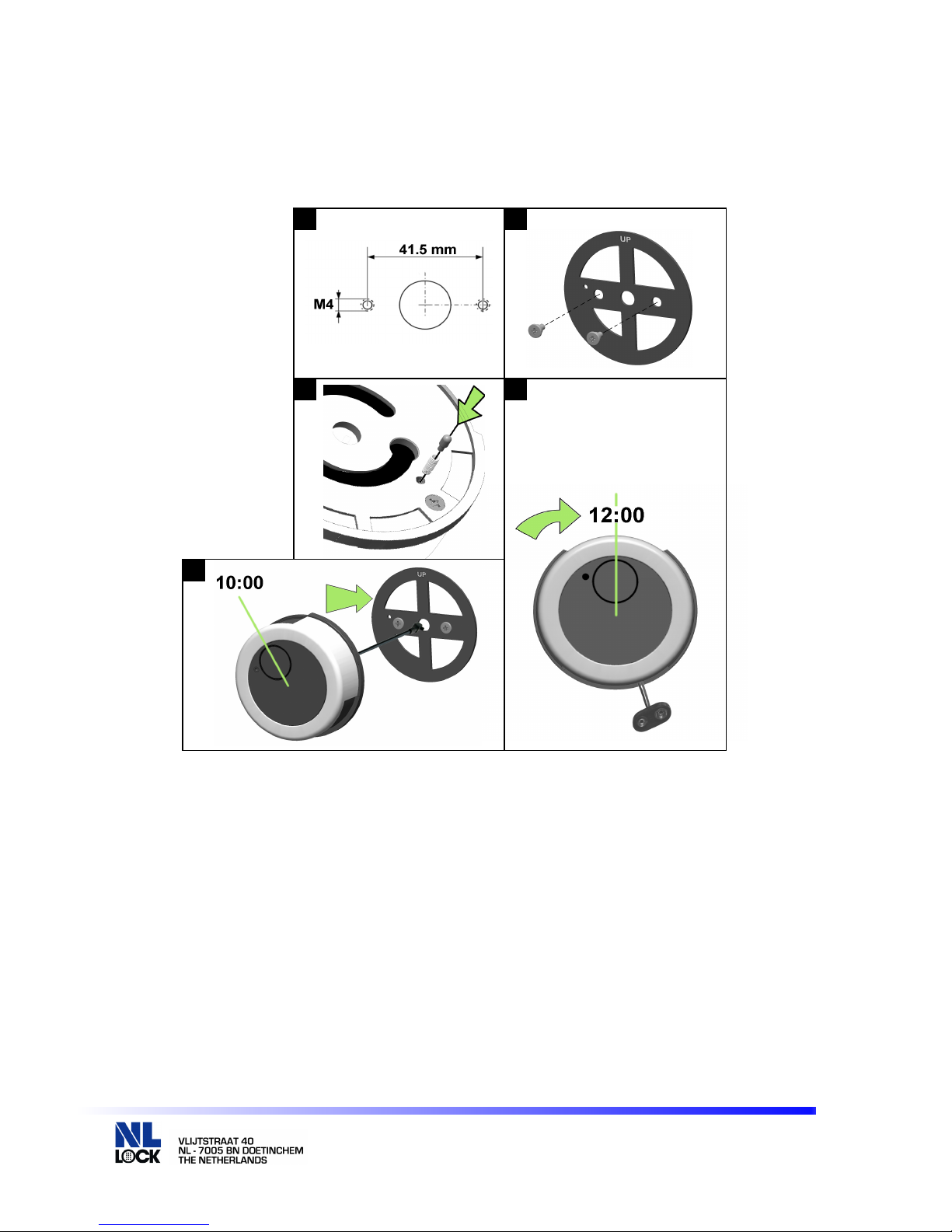
STATIONARY MOUNTING:
The diameter of the cable hole should be minimum 9 mm, maximum 12 mm. The
hole must be deburred well to avoid damage to the cable.
4
Prepare the mounting and cable holes according to picture 1. Hold the bearing plate
in a way against the mounting surface that “UP LOCK” is readable on top (picture 2).
Affix the bearing with the two mounting adapter (M4). Insert first the spring and then
the pin into the hole on the back cover (picture 3). Route the cable through the cable
hole, hold the unit at an approximately 10:00 o’clock position (picture 4), and slide it
on the mounting adapters. Turn unit clockwise until it clicks into stationary position at
12:00.
The Bravo entry unit can now not be removed!
Connect one (1) battery to the battery clip. Only use 9V-ALKALINE batteries from
brand name manufacturers like DURACELL™.
BR50•10 Technical Manual 090729
© 2008 Lock Technology BV
Page 2 of 3
Page 3
1 2 3
5
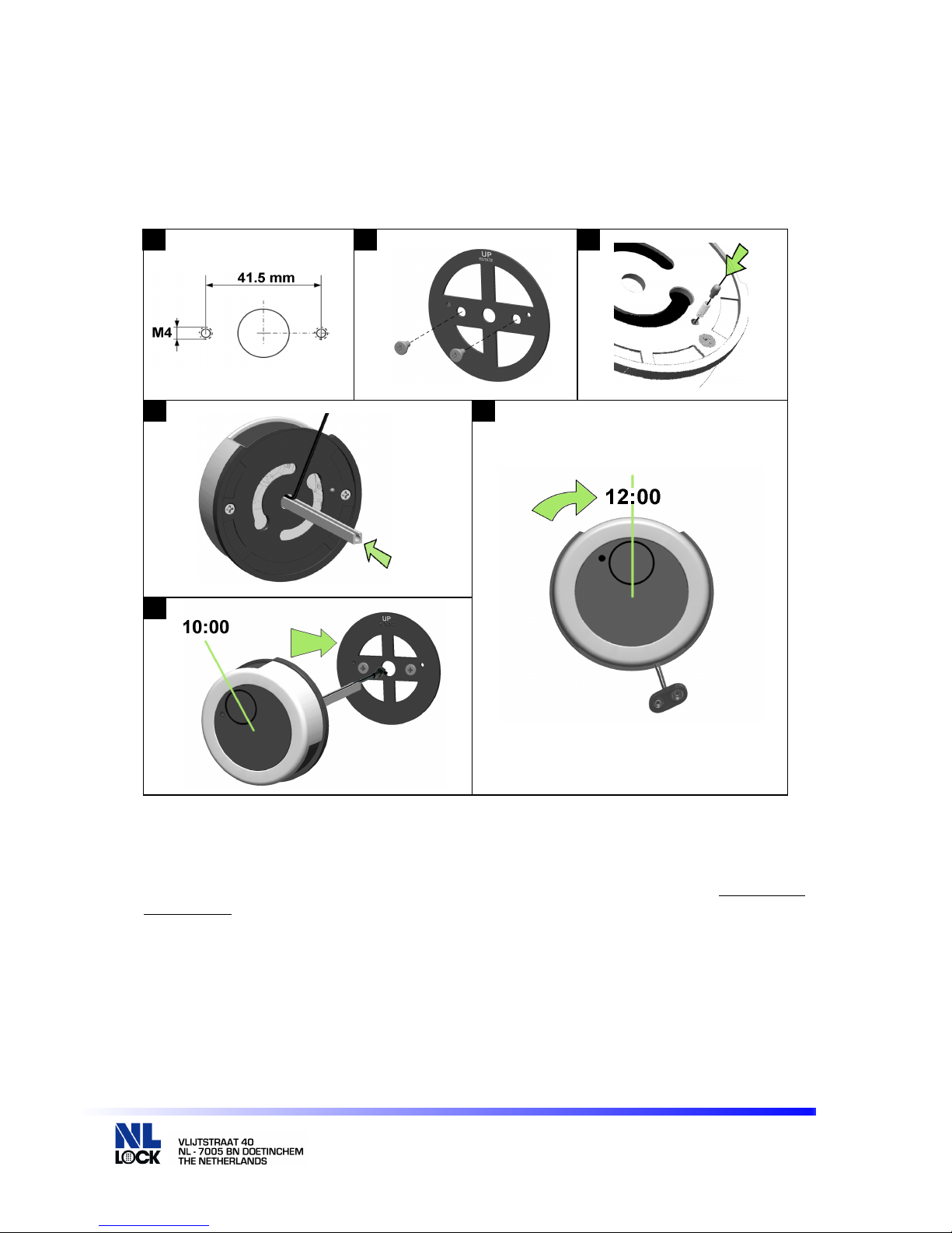
As TURNABLE ENTRY UNIT with NL LOCK StraightBolt lock EM35•20:
The diameter of the cable hole should be minimum 9 mm, maximum 12 mm. The hole must
be deburred well to avoid damage to the cable. Cut the grooved shaft to the appropriate
length: Measure door thickness (from mounting surface of the Entry unit to the mounting
surface of the lock) and add 40 mm (1.6”).
4
6
Prepare the mounting and cable holes according to picture 1. Hold the bearing plate in a
way against the mounting surface that “UP ROTATE” is readable on top (picture 2). Affix the
bearing with the two mounting adapter (M4) Do not overtighten. Insert first the spring and
then the pin into the hole on the back cover (picture 3). Insert the grooved shaft, with the cutoff edge first, all the way into the entry housing (picture 4). Now push the cable into the
groove until flat over the entire length of the shaft. Route the cable and shaft through the
spindle hole of the door, hold the unit at an approximately 10:00 o’clock position, and slide it
on the mounting adapters (picture 5). Turn unit clockwise until it clicks into straight position
at 12:00.
The Bravo entry unit will not be detachable once the lock is installed.
Connect one (1) battery to the battery clip. Only use 9V-ALKALINE batteries from brand
name manufacturers like DURACELL™.
BR50•10 Technical Manual 090729
© 2008 Lock Technology BV
Page 3 of 3
 Loading...