


1
Operating Manual
Infrared thermometer
Model:IT-121
Professional Fast Accurate

2
CONTENTS
1 I n t r o d u c t i o n . . . . . . . . . . . . . . . . … … … … … … … … … … … … … … … … 3
1.1Product intended use……………………………………………………………3
2 Ba si c p ri n ci p le ……… …… … …… ……… …… … …… …… … …… … … 3
3 Pr o d u c t f e a t u r e … … … … … … … … … … … … … … … … … … … … … 3
4 T e c h n i c a l pa r a m e t e r s …… … … … … … … … … … … … … … … … … … 4
5 S h ap e st r u ct u r e …… … … … ……… … … … … …… … … … … …… … … 4
6 Di spl ay ico n de fin iti on … … … … … … ………… …………… ……… 5
7 F u n c t i o n k e y s … … … … … … … … … … … … … … … … … … … … … 6
8 Se t t i n g s …… … … … … … … … … … … … … … … … … … … … … … … … 7
9 Me a s ur i ng me th o d … …… … … …… … …… … ……… … …… … … …… 7
9. 1Forehe ad tem peratu re meas urement……………… ………………… …7
9 . 2 E a r t e m p e r a t u r e m e a s u r e m e n t … … … … … … … … … … … … 8
9.3 Object temperature measurement……………………………………………8
9.4 Ambient temperature measurement……………………………………………9
10. Replacement of batteries………………………………………..……………9
11Maintenance and matters needing attention ..................………………….…9
12.Troubleshooting....................................................................................................10
13. Commitment to quality and after-sales service ………………………….…14
14. Manufacturer information…………………………... ……………………14

3
1. Introduction
IT-121 measures the body temperature through receiving the infrared energy
radiation from the surface of objects. It is with forehead temperature mode,and ear
temperature mode. The measurement result directly shows on the LCD screen It is
easy, hygiene and accurate.
The device is widely used for home healthcare, medical institutes and many other
occasions.
The product is mainly composed with infrared temperature sensors, signal
receiving processor, buttons, buzzer, LCD display, battery, etc
1.1 Product intended use
The infrared thermometer is intend for the measurement and monitoring of
human body temperature by doctor or customers in the hospital or home, it is used
alone for human beings for all ages.
2. principle
Any object in which temperature is higher than absolute zero degree will transmit
some infrared radiation energy according to its own temperature. The radiation
energy and its distribution per wavelength are closely associated with its surface
temperature. Based on the principle, it is possible to measure the forehead surface
temperature and then adjust the offset between forehead temperature and actual body
temperature, which will result in the correct display of body temperature.
3. Product features
●Contact-type infrared measurement
;
●Forehead, Eear temperature, dual modes of measurement
;
●Hi definition dual color LED backlit, clearly and softly display
●Fever alarm function (defaut alarm value is 38.0°C and above)
●Capacity of storing 20 sets measurements;
●Dual temperature units Cesis and Fahrenheit optional.
●Automatic shut-down and power-saving.

4
4. Technical parameters
Table1
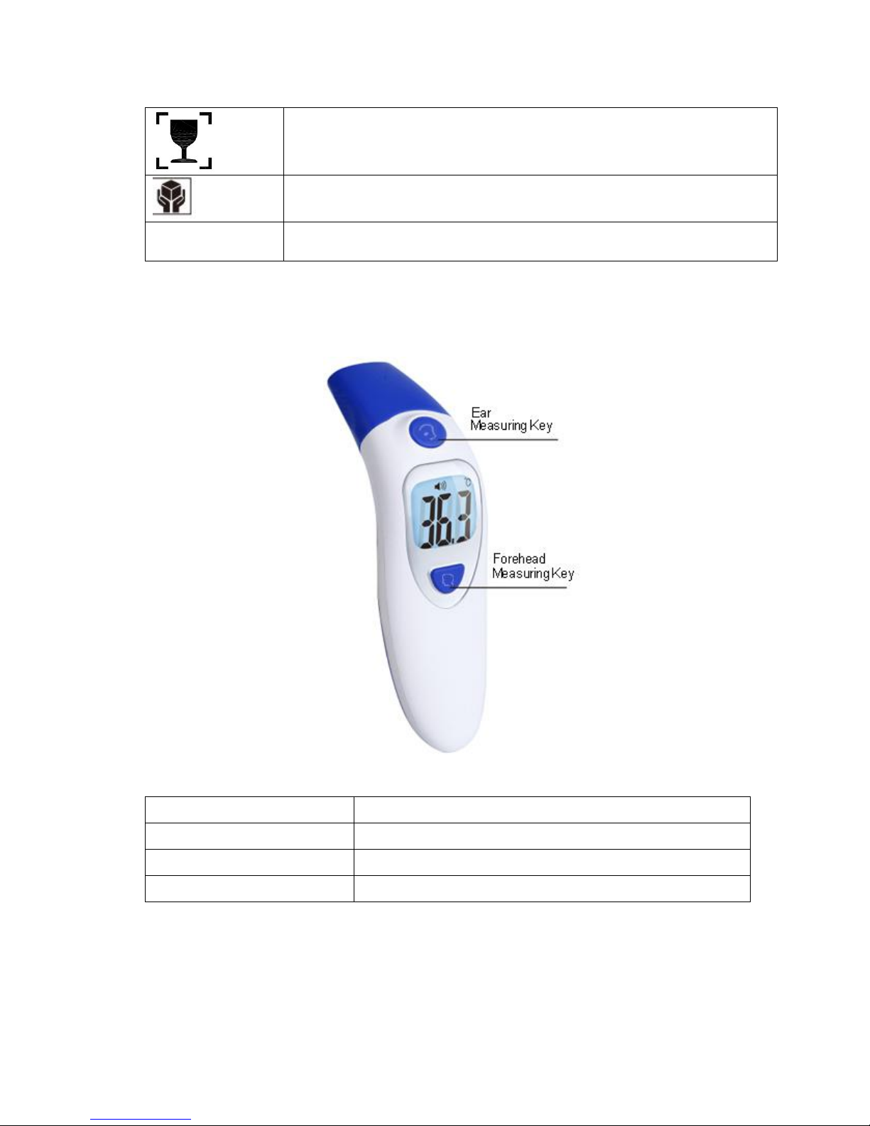
5. Shape structure
1. Mode conversion cover; 2. Infrared probe;
3. Measuring key; 4. LCD display;
5. Memories key and conversion key
6. handle 7. Battery cover
Measurement method
Contact-Type
Measurement Mode
Body Mode
32.0°C~42.9°C(89.6°F~109.2°F)
Surface Mode
0°C~100°C(32°F~212°F)
Measurement accuracy
Body Mode
±0.3°C(0.54°F)
Surface Mode
±1.0°C(1.8°F)
Display resolution
0.1°C/°F
Operating environment
16° C ~ 35 ° C (60.8° F to 95 ° F) ≦ 85% moisture
condensation
Storage condition
- 25 ° ~ 55 ° C - (-13° F to 131 ° F)≦90% moisture
condensation
Power supply
DC1.5V×2
Power consumption
When off≦10 uw
Auto power-off
When measuring≦ 30 mw
In 30 seconds
Dimensions
30mm * 44 mm *152 mm(length x width x height)
Weight
About 72 g (without battery)
Dimensions
152mm * 44 mm *30mm(length x width x height)

5
6. Display icon definition
Table 2
Icon definition
icon
Definition
Measuring
mode1
Forehead and Object temperature
Measuring
mode2
Ear temperature measurement
Temperature unit
°F or °C
Celsius degree; Fahrenheit degree
The icon means can convert between °F and °C
Ambient Mode.
Ambient temperature measurement
Battery capacity
Indicates low battery status
Memory symbol
M
Record the latest 20sets memories
Read the manual
before use
Precautions for use
Don’t dispose with household waste after use
Flammable and explosive
Manufacturer
BF type application device
Keep dry
Upward
6
Fragile, handle with care
IS LOVE
7. Function keys
Table 3
Function key
functional description
Measuring key
Press to measure
Memories key
Press to get the latest 20 sets memories temp.
Conversion key
Keeping press in 5s to adjust ° C / ° F, when setup
8. Settings
A: Memory mode
:

7
Open the battery cover and install the batteries, then the screen display all symbols.
press the Memory key to check the lastest 20 sets measurement value.
Note:
a. The record order is 20,19,18...1 and so on.
b. The record will be deleted when uninstall the batteries.
B: Temperature unit setting
:
Open the battery cover and install the batteries, then the screen display all the
symbols and off. Press the memory key for 5s and the screen display “- - - - ° C”,
press the memory key one more time to change into “° F” and off after 3s. then the
setting is done.
Note: The default temperature unit is “°C”. The setting will come back to the
default when uninstall the batteries.
9. Measuring method
9.1 Forehead temperature measurement.
●Install the batteries to power on, make sure the screen display “ ”and the mode
conversion cover before the measurement.
●Hold the thermometer and point the device to the forehead,
measurement key directly or keep pressing measurement key, scan forehead ,when
buzzer beeps, the temp.will display on the LCD screen.Keep the probe cover
contacting the forehead when measuring.
9.2 Ear temperature measurement
● Take off the mode conversion cover, then put on the ear probe cover .Insert the
probe into the ear. Press the measuring key to measure directly,when the buzzer
beeps, the temperature will display on the screen.
● Make sure that the probe cover is taken off and converted to the Ear and ambient
measuring mode

8
Prompt
Don’t push hard into the ear to avoid hurting the eardrum
9.3 The object temperature measurement.
● Take off the Cover of mode conversion, point the thermometer to the object, keep
the probe 3~5mm to the object. Press the measuring key to measure directly,when
the buzzer beeps, the temperature will display on the screen.
● Make sure that the cover of mode conversion is taken off and converted to the Ear
and the object mode.
Prompt
1. All operation should do when power on;
2. All settings will come to default when uninstall the batteries. If need adjust the
settings, please power on and make the new settings..
3. Temperature unit setting must in the state of power off.
4. Memory value can be inquired when power off or any measurement mode
according to 8 (B)
5. The thermometer will be auto off after 30s when idle.
6. Measurement must be carried out when power on and the backlight is off.
7. When the measured temperature value is 38℃and above, the backlight is red
and beep while the other value is green. When the measurement vale is between
37.5-37.9℃, it is considered low fever, advice to consult the doctor.
9.4 Ambient temperature measurement
1.Take off the mode conversion cover.

9
2.point the prove to the air and press the start key.
10. Replacement of batteries
●The battery life is approx. 3000 readings one year and 90 minutes when in
constant use.
●Open the battery cover, and remove the old battery.
● Put in new battery, and take care of the direction of the electrodes.
Prompt
1.when not used for a long time, please take out the battery to prevent leakage. It
is forbidden to put waste battery in the fire.
2. According to local regulations, properly handle the waste batteries to avoid
pollution.
11. Maintenance and matters needing attention
Please keep the inner cavity of the sensors and probes clean, otherwise it will
affect the measuring accuracy.
Cleaning methods:
1. The device only needs routine cleaning, and period or times can be decided
according to user’s need.
2. The surface cleaning: use a clean soft cloth or cotton swab stick moistened with a
little medical alcohol or water to wipe the dirt.
3. Probe and sensor inner cavity cleaning: with a clean soft cloth or cotton swab
dipped with a little medical alcohol gently wipe the probe at the top of the inner
cavity or sensors, and do not use until the alcohol completely evaporates.
●Before use, please read the instructions, and make sure the battery has been
installed.
●Prohibit the thermometer into any liquid, no long time use in high or low
temperature environment.
●No collision, falling and sharp objects mix, it is forbidden to disassemble the
thermometer.
●Do not use in strong electromagnetic interference environment.
●The thermometer is placed in the position not touched by children.
●Practice is suggested to get familiar with the measurement methods; try not to
change the product factory settings.
●The measurement results cannot replace the physician diagnosis.
●Use the thermometer in a stable temperature environment. If the environment
temperature changes too much, for example from outdoor to indoor, please put
the
thermometer and wait for about half an hour minutes before measuring.

10
● Don't measure body temperature after measuring extremely high or low
temperature. Put the device for 10 minutes before measuring.
●Try to avoid using the thermometer when drying the hair, drenching water,
sweating,
and putting on skin cosmetics. Don’t measure the temperature after doing sports,
washing and 30 minutes before dinner.
●No special maintenance is needed to the use process. Please contact the vendor or
manufacturer for fault.
12. Troubleshooting
Table 4
Diagnosis
Solution
The screen shows "Lo" or "Hi”
1.Check the measurement object. It is
unable to ensure the measurement of the
forehead hair, water, sweating, and
applying cosmetics case.
2.Check the operation environment.
Environment changes will greatly
influence the measurement.
3.Temperature change is too big or the
thermometer tests target of low
temperature immediately after being
switched from a high temperature
measuring. It's better to use after 10
minutes to achieve a new heat balance.
4. The measured body temperature is
higher than 42.9° C or lower then
32.0 ° C
5. The measured object is not corrent.
The screen shows "Er1”
1. The environment temperature is
exceed the normal working arrange
which is 16° C ~ 35 ° C (60.8° F to
95 ° F)
Buttons have no response
2. Load and unload the battery
3. Check if the setting is in the
progress
No display or display abnormal
Unload the batteries and load again
Power off when open
Check the battery, load and unload the
battery again
11
Table 5
Guidance and manufacturer ’s declaration-electromagnetic emissions
The IT-121 is intended for using in the electromagnetic environment specified below. The customer or the
user of theIT-121 should assure that it is used in such an environment.
Emissions test
Compliance
Electromagnetic environment-guidance
RF emissions
CISPR 11
Group 1
TheIT-121 uses RF energy only for its internal function.
Therefore, its RF emissions are very low and are not likely to
cause and interference in nearby electronic equipment.
RF emissions
CISPR 11
Class B
TheIT-121 is suitable for use in all establishments other than
domestic and those directly connected to the public low-voltage
power supply network that supplies buildings used for domestic
purposes.
Harmonic emissions
IEC 61000-3-2
N/A
Voltage fluctuations
/flicker emissions
IEC 61000-3-3
N/A
Table 6
Guidance and manufacturer ’s declaration-electromagnetic immunity
TheIT-121 is intended for use in the electromagnetic environment specified below. The customer or the user
of theIT-121 should assure that it is used in such an environment.
Immunity test
IEC60601 test level
Compliance
level
Electromagnetic
environment -guidance
Electrostatic
discharge
(ESD)
IEC 61000-4-2
±2,±4,
±6kV for
Contact discharge
±2,±4,±8kV
air
discharge
±2,±4,
±6kV
for
Contact
discharge
Floors should be wood, concrete or ceramic
tile. If floors are covered with synthetic material,
the relative humidity should be at least 30%
Electrical fast
transient/burst
IEC 61000-4-4
±2 kV for a.c. power
lines
±1 kV for d.c. power
lines
N/A
Mains power quality should be that of a typical
commercial or hospital environment.
Surge
IEC 61000-4-5
±1 kV line(s) to
line(s)
±2 kV line(s) to
earth
N/A
Mains power quality should be that of a typical
commercial or hospital environment.

12
Voltage dips,
short
interruptions
and voltage
variations in
power supply
input lines
IEC 61000-4-11
<5%UT
(>95 dip in UT) for 0.5
cycle
40% UT
(60% dip in UT) for 5
cycles
70% U
T
(30% dip in UT) for 25
cycles
<5% UT (>95% dip in
UT for 5 s
N/A
Mains power quality should be that of a typical
commercial or hospital environment. If the user of
theIT-121 requires continued operation during
power mains interruptions, it is recommended that
theIT-121 be powered from an uninterruptible
power supply or a battery
Power
frequency
(50/60Hz)
magnetic field
IEC 61000-4-8
3 A/m
3 A/m
Power frequency magnetic fields should be at
levels characteristic of a typical location in a
typical commercial or hospital environment
NOTE UTis the a.c. mains voltage prior to application of the test level.
Table 7
Guidance and manufacturer ’s declaration-electromagnetic immunity
The IT-121 is intended for use in the electromagnetic environment specified below. The customer or the user
Immunity test
IEC 60601 test level
Compliance
level
Electromagnetic environment-guidance
Conducted RF
IEC 61000-4-6
3Vrms
150kHz to 80MHz
N/A
Portable and mobile RF communications
equipment should be used no closer to any part of
theIT-121 including cables, than the
recommended separation distance calculated from
the equation applicable to the frequency of the
transmitter.
Recommended separation distance
d=1.2 P
13
Radiated RF
IEC 61000-4-3
3V/m
80kHz to 2.5GHz
3V/m
d=1.2 P 80MHz to 800MHz
d=2.3 P 800MHz to 2.5MHz
Here P is the maximum output power rating of the
transmitter in watts (W) according to the transmitter
manufacturer and d is the recommended separation
distance in meters (m). Field strengths form fixed
RF transmitters, as determined by an
electromagnetic site survey, should be less than the
compliance
b
level in each frequency range.
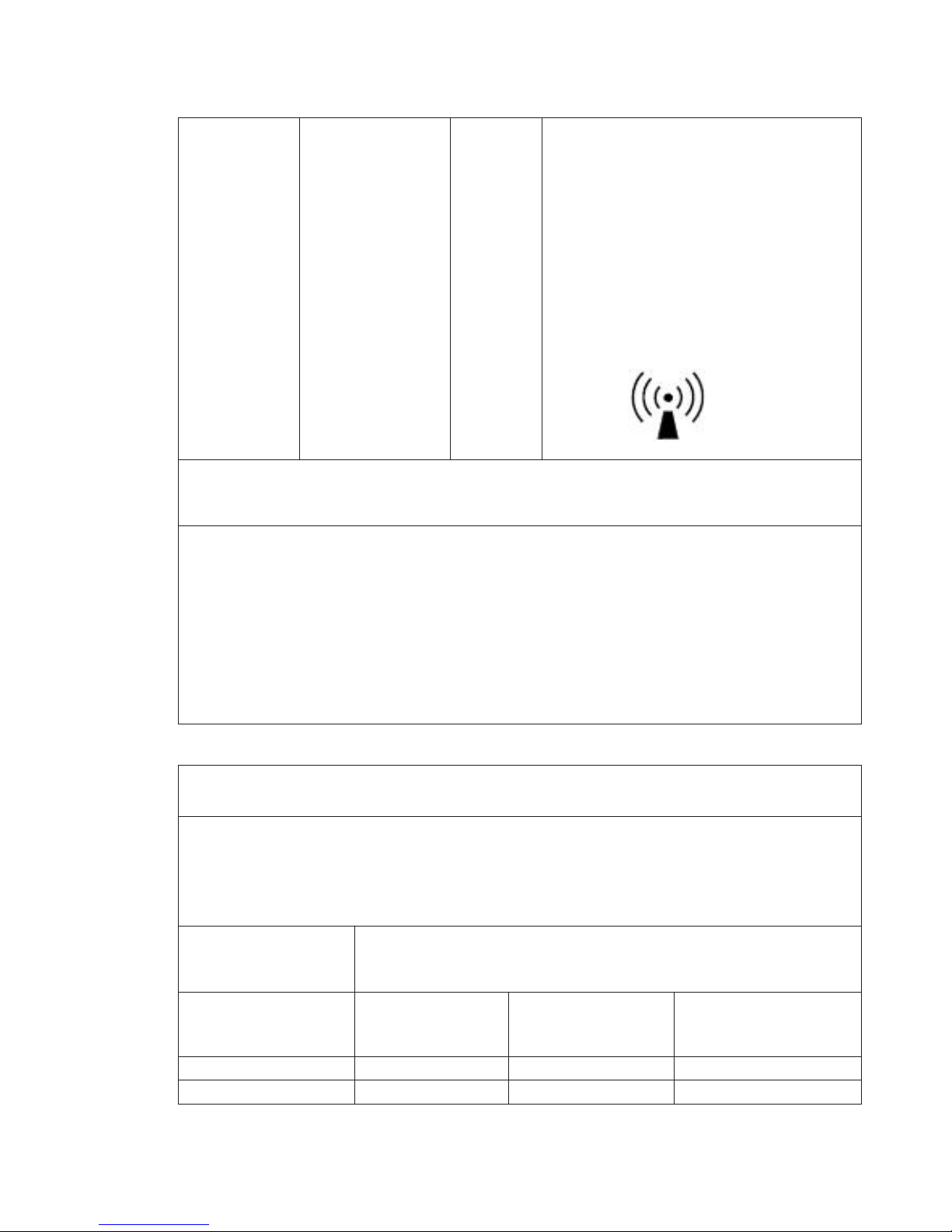
Interference may occur in the vicinity of equipment
marked with the following symbol:
NOTE 1 At 90MHz and 800MHz, the higher frequency range applies.
NOTE 2 These guidelines may not apply in all situations. Electromagnetic propagation is affected by absorption
and reflection from structures, objects and people.
a
Field strengths from fixed transmitters, such as base stations for radio (cellular/cordless)
telephones and land mobile
radios, amateur radio, AM and FM radio broadcast and TV
broadcast cannot be predicted theoretically with accuracy. To
assess the electromagnetic
environment due to fixed RF transmitters, anelectromagnetic site survey should be
considered. If the measured field strength in the location in which theIT-121 is used exceeds the applicable RF
compliance level above, theIT-121 should be observed to
verify normal operation. If abnormal performance is
observed, additional measures may
be necessary, such as reorienting or relocating theIT-121
b
Over the frequency range 150kHz to 80MHz, field strengths should be less than 3V/m.
Table 8
Recommended separation distances between portable and mobile RF communications equipment and
the IT-121
TheIT-121 is intended for use in an electromagnetic environment in which radiated RF disturbances are
controlled. The customer or the user of theIT-121 can help prevent electromagnetic interference by
maintaining a minimum distance between portable and mobile RF communications equipment (transmitters)
and theIT-121 as recommended below, according to the maximum output power of the communications
equipment.
Rated maximum output
power of transmitter
W
Separation distance according to frequency of transmitter
m
Rated
maximum
output power
150kHz to 80MHz
d =1.2 P
80MHz to 800MHz
d =1.2 P
800MHz to 2.5GHz
d =2.3 P
0.01
0.01
0.12
0.23
0.1
0.1
0.38
0.73

14
111.2
2.3
10103.8
7.3
100
1001223
For transmitters rated at a maximum output power not listed above, the recommended separation distance d
in meters (m) can be estimated using the equation applicable to the frequency of the transmitter, where P is
the maximum output power rating of the transmitter in watts (W) according to the transmitter manufacturer.
NOTE 1 At 80MHz and 800MHz, the separation distance for the higher frequency range applies.
NOTE 2 These guidelines may not apply in all situations. Electromagnetic propagation is affected by
absorption and reflection from structures, objects and people.
13. Commitment to quality and after-sales service
This product provides 3 year free maintenance service.
Note: The free service does not include the failure and damage due to user’s
personal reasons or unauthorized disassembling.
Prompt
Please keep the purchase vouchers to facilitate future maintenance.
14. Manufacturer information
Shenzhen Brav Electronic Technologies Co., Ltd.
Address: 4/F, Block 11, Tongfuyu Industrial District, Lezhujiao, Jiuwei, Hangcheng,
Baoan, Shenzhen, P.R. China
Tel: 0755-29781489 Fax: 0755-29569480
Http://www.brav.com.cn
 Loading...