

Page 1

403906 Rev. B
January
2019
Original Instructions
ISO 9001:2015
www.braunability.com/international
631 West 11th Street, Winamac, IN 46996, USA
Phone: +1 574 946 6153 Fax: +1 574 946 4670
International
Inboard Lift
Public Use
Wheelchair Lifts
Solid Platform
Owner Manual
Manufacturing Revision Level: Rev. A
E Series
Page 2
Consult your local BraunAbility® dealer regarding warranty policy.
www.braunability.com/international
OWNER'S WARRANTY REGISTRATION
War. Card 07.ai
PURCHASED FROM
DATE INSTALLED
NAME
ADDRESS
CITY
TELEPHONE
TO VALIDATE WARRANTY
REGISTRATION CARDS MUST BE RETURNED TO THE BRAUN CORPORATION.
OWNER
STATE ZIP
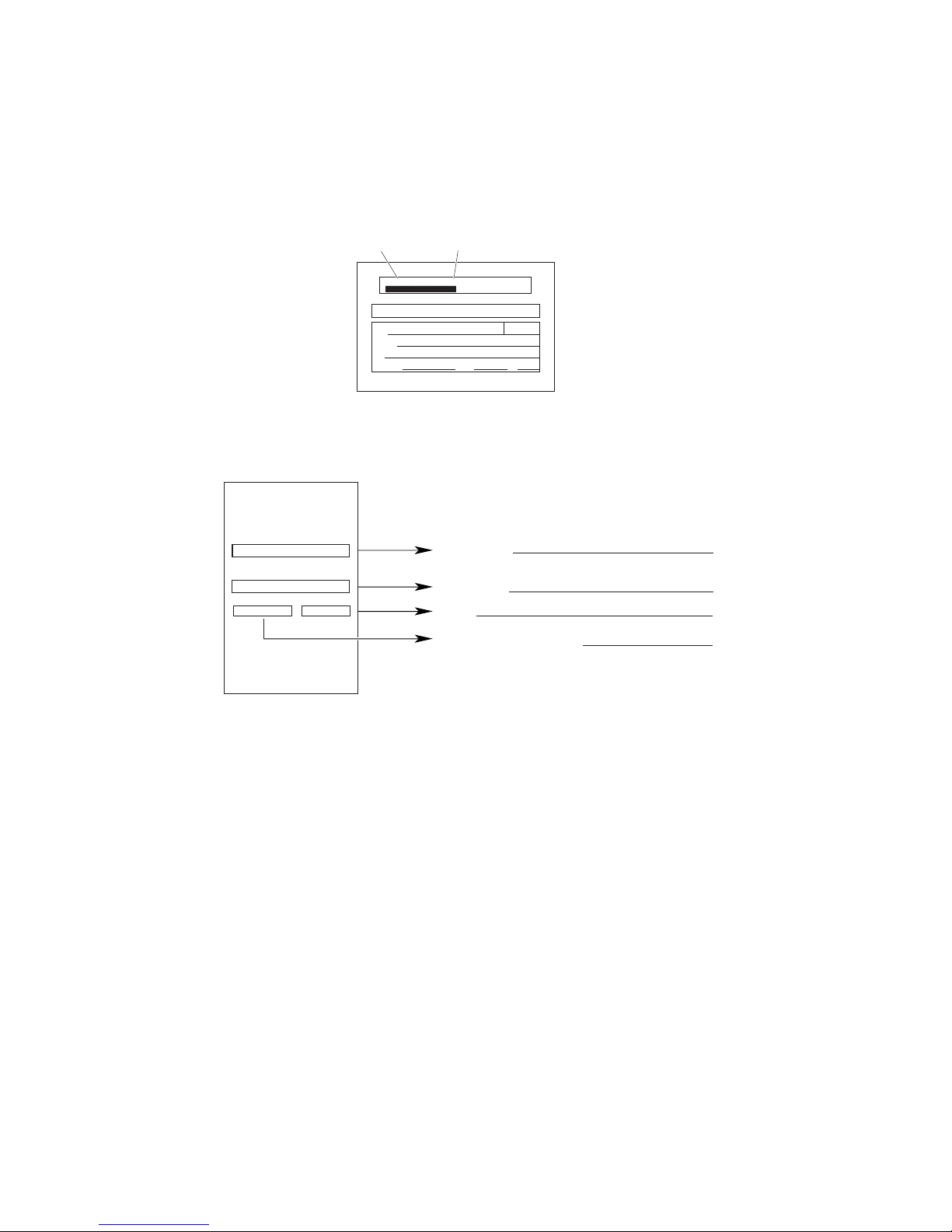
Sample Warranty/Registration Card
XXXXXXXXXX XX-XXXXX
Serial No.
Model No.
Sample Serial Number Identication Tag
Model No.
Serial No.
Rev.
Date of Manufacture
BraunAbility
®
INDIANA, USA
BRAUNABILITY.COM
REV
XXXXXXX
SERIAL NUMBER
XXXX Use Lift
Max. Lifting Capacity - XXX lb
XXXXXXX
MODEL NUMBER
MFG DATE
XXXXXXX
X
Warranty
Page 3

Contents
Installation and Service Safety ....................................................... 2, 3
Lift Operation Safety ....................................................................... 4-6
Specications ..................................................................................... 7
Lift Terminology .................................................................................. 8
Lift Installation
Position Lift ......................................................................... 9, 10
Secure Lift ............................................................................... 11
Power Cable and Ground Cable ........................................ 12-13
Platform Angle Adjustment ..................................................... 14
Tower Microswitch Adjustment ............................................... 15
Installer Verication ........................................................... 16-17
Lift Operation Safety ................................................................... 18-20
Lift Operating Instructions ........................................................... 21-23
Manual Operating Instructions ................................................... 24, 25
Maintenance and Lubrication ...................................................... 26-30
Declaration of Conformity ................................................................. 31
Document Cross Reference
Service Manual 403907
Page 1
Page 4
Installation and Service Safety
Page 2
SAFETY FIRST! Know That ....
The information contained in
this manual and supplements (if
included), is provided for your
use and safety. Familiarity with
proper installation, operation,
maintenance and service procedures is necessary to ensure
safe, trouble-free lift operation.
Safety precautions are provided
to identify potentially hazardous
situations and provide instruction on how to avoid them.
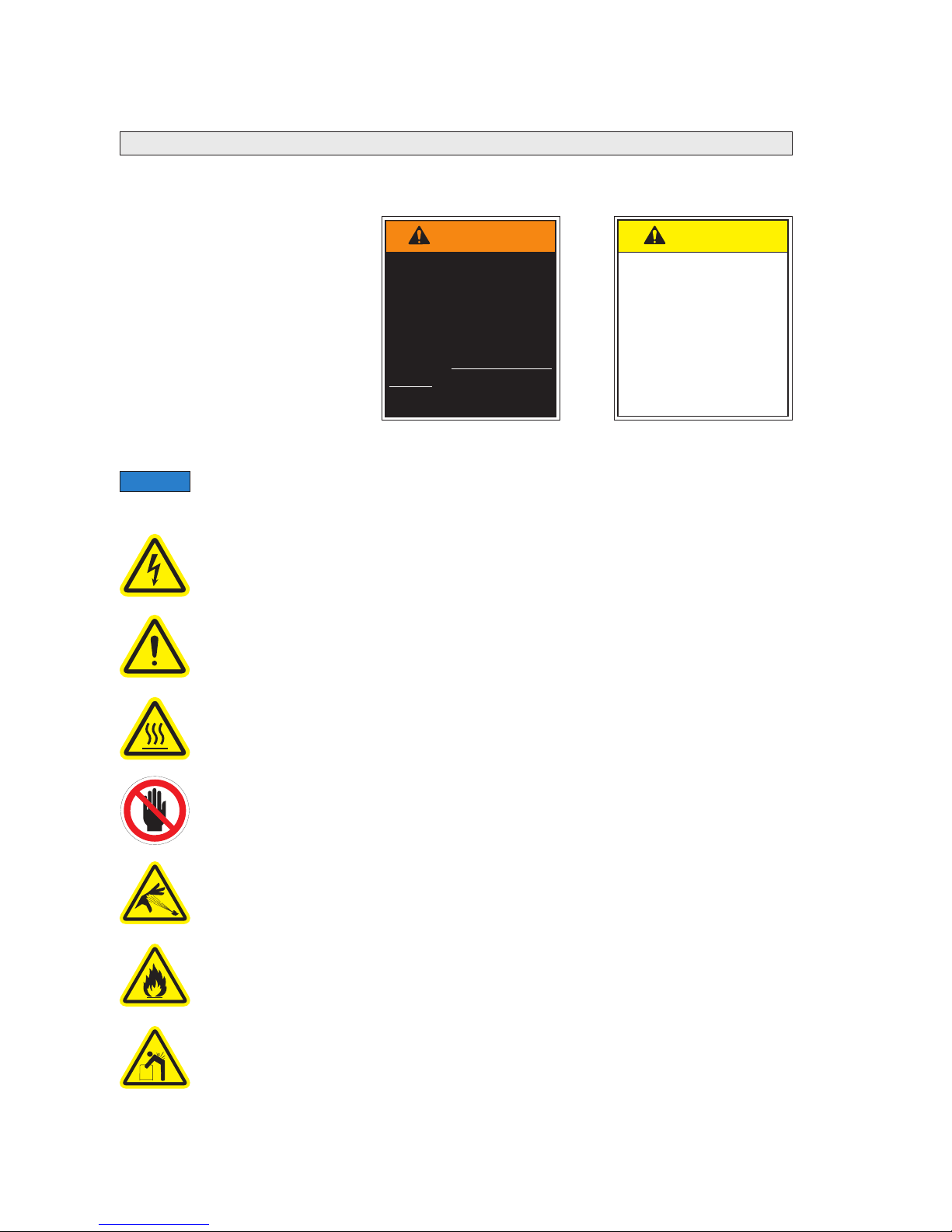
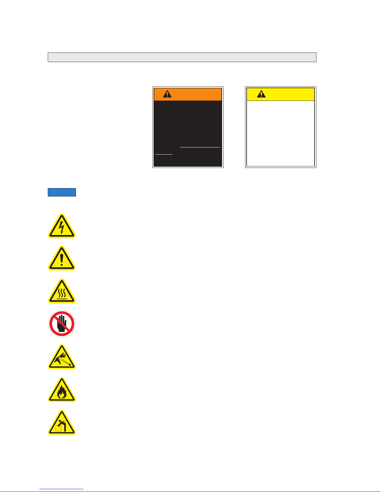
Safety Symbols
This symbol indicates
important information
regarding how to
avoid a hazardous
situation that could
result in minor personal injury or property
damage.
C
A
UTION
These symbols will appear throughout this manual as well as on the labels posted on your lift.
Recognize the seriousness of this information.
This symbol indicates a device weighs in excess of 139kg (306 lbs).
Use of a fork lift or hoist is required.
This symbol indicates the presence of a re hazard. Avoid open ames or
sparks when working with ammable materials to prevent injury or damage.
This symbol indicates the presence of high pressure hydraulic hoses. Use
appropriate personal protective equipment when working on hydraulic system.
This symbol indicates an area to avoid bodily contact to prevent injury.
36514
This symbol indicates that a condition where injury or damage could occur if
contact is made with the hot surface.
36512
This symbol indicates that a condition where damage to the equipment resulting
in injury to the operator could occur if operational procedures are not followed. To
reduce the risk of damage or injury, refer to accompanying documents, follow all
steps or procedures as instructed.
This symbol indicates that there are dangerous energy levels present inside the
enclosure of this product. To reduce the risk of re or electric shock, do not attempt
to open the enclosure or gain access to areas where you are not instructed to do
so. Refer servicing to qualied service personnel only.
36513
Additional information provided to help clarify or detail a specic subject.
NOTICE
This symbol indicates
important safety information regarding a
potentially hazardous
situation that could
result in serious bodily
injury and/or property
damage.
W
A
RNING
Page 5
Installation and Service Safety
Page 3
Read this manual, supplement(s) and lift-posted
operating instructions decals before performing
installation, operation, or service procedures.
Use appropriate personal protective equipment when
installing and servicing lift.
Remove any obstructions within the lift mounting/
operating area prior to beginning installation procedures.
Install lift and power platform to fully folded position
before removing shipping straps.
Do not fold or unfold the platform prior to positive
securement of base plate mounting hardware.
Check for obstructions such as gas lines, wires,
exhaust, etc. before drilling or cutting during installation
procedures.
Installation and Service Safety Precautions
Route all cables clear of exhaust system, other hot areas, moving parts, wet areas, etc.
Risk of electrical shock or re! Use extra care when making electrical connections.
Connect and secure as outlined in Installation Instructions and Wiring Diagrams.
Adjust platform angle and oor level positioning of bridge plate before operating lift with
passenger.
Maintenance and repairs must be performed only by authorized service personnel.
Perform maintenance and lubrication procedures exactly as outlined in the
Maintenance and Lubrication Schedule contained in this manual.
Disconnect the power cable at the battery prior to servicing.
Never modify (alter) a BraunAbility lift.
Replacement parts must be BraunAbility authorized replacements.
Never install screws or fasteners (other than factory equipped).
Whenever replacing a hydraulic cylinder or seals, lower platform fully.
Failure to follow these safety precautions may result in serious bodily injury and/or
property damage.
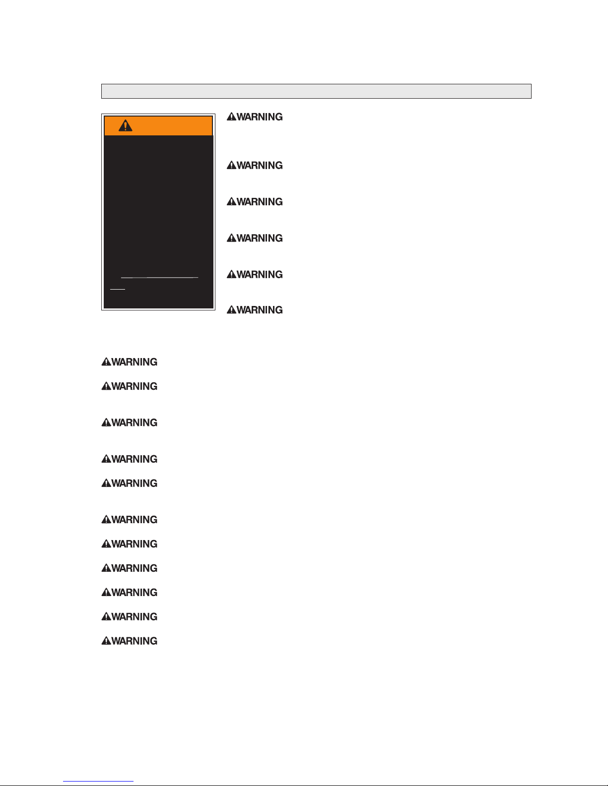
W
A
RNING
If installation, maintenance or repair
procedures cannot
be completed exactly as provided in
this manual or if the
instructions are not
fully understood,
contact BraunAbility
immediately. Failure
to do so may result
in serious bodily injury and/or property
damage.
Page 6
Lift Operation Safety
Page 4
SAFETY FIRST! Know That ....
The information contained in
this manual and supplements (if
included), is provided for your
use and safety. Familiarity with
proper installation, operation,
maintenance and service procedures is necessary to ensure
safe, trouble-free lift operation.
Safety precautions are provided
to identify potentially hazardous
situations and provide instruction on how to avoid them.
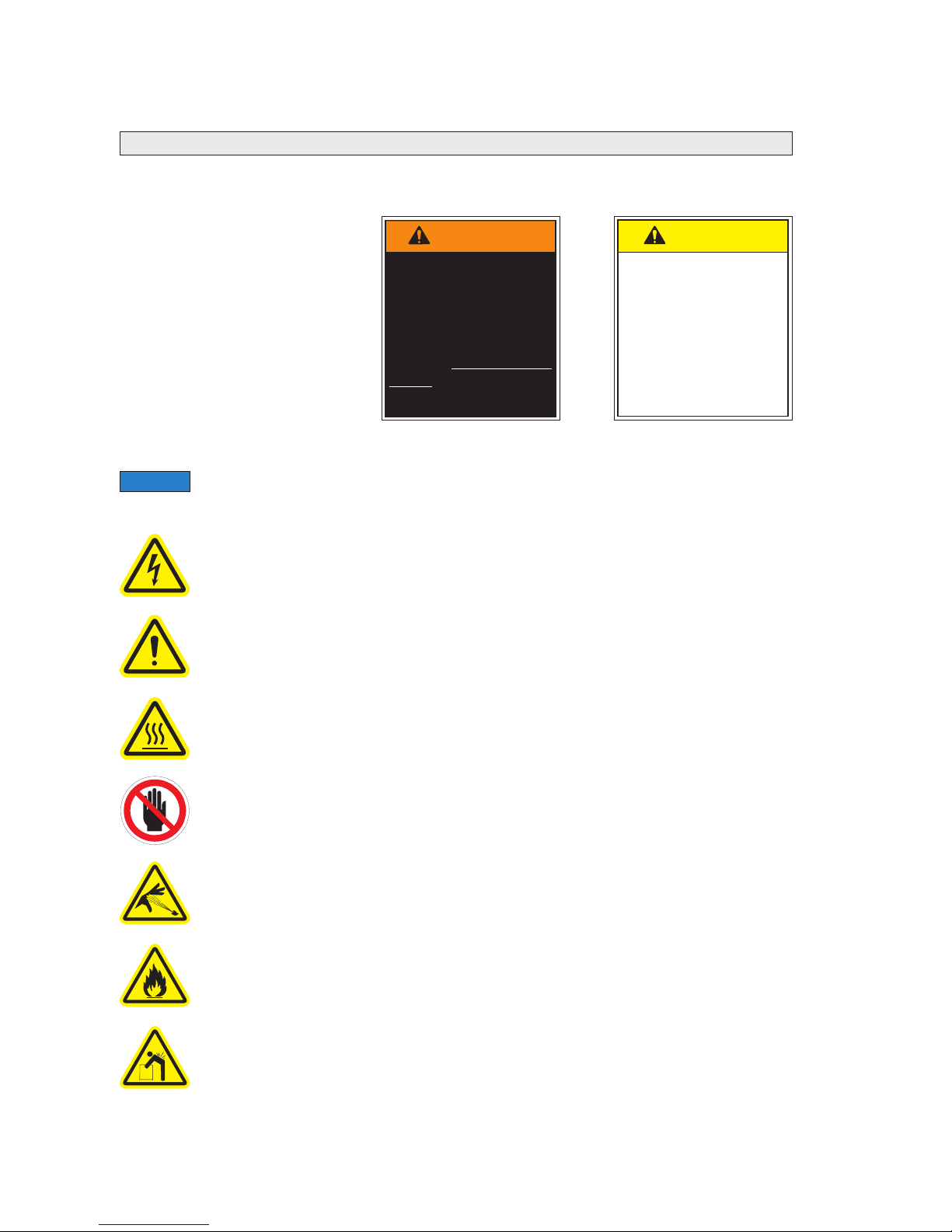
Safety Symbols
This symbol indicates
important information
regarding how to
avoid a hazardous
situation that could
result in minor personal injury or property
damage.
C
A
UTION
These symbols will appear throughout this manual as well as on the labels posted on your lift.
Recognize the seriousness of this information.
This symbol indicates a device weighs in excess of 139kg (306 lbs).
Use of a fork lift or hoist is required.
This symbol indicates the presence of a re hazard. Avoid open ames or
sparks when working with ammable materials to prevent injury or damage.
This symbol indicates the presence of high pressure hydraulic hoses. Use
appropriate personal protective equipment when working on hydraulic system.
This symbol indicates an area to avoid bodily contact to prevent injury.
36514
This symbol indicates that a condition where injury or damage could occur if
contact is made with the hot surface.
36512
This symbol indicates that a condition where damage to the equipment resulting
in injury to the operator could occur if operational procedures are not followed. To
reduce the risk of damage or injury, refer to accompanying documents, follow all
steps or procedures as instructed.
This symbol indicates that there are dangerous energy levels present inside the
enclosure of this product. To reduce the risk of re or electric shock, do not attempt
to open the enclosure or gain access to areas where you are not instructed to do
so. Refer servicing to qualied service personnel only.
36513
Additional information provided to help clarify or detail a specic subject.
NOTICE
This symbol indicates
important safety information regarding a
potentially hazardous
situation that could
result in serious bodily
injury and/or property
damage.
W
A
RNING
Page 7
Lift Operation Safety
Page 5
Lift Operation Safety Precautions
W
A
RNING
If the lift operating
instructions, manual
operating instructions
and/or lift operation
safety precautions are
not fully understood,
contact BraunAbility
immediately. Failure
to do so may result in
serious bodily injury
and/or property damage.
Read manual and supplement(s) before operating lift.
Read and become familiar with all safety precautions,
operation notes and details, operating instructions and
manual operating instructions before operating the lift.
Load and unload on level surface only.
Engage vehicle parking brake before operating lift.
Provide adequate clearance outside the vehicle to accommodate the lift before opening lift door(s) or operating lift.
Inspect lift before operation. Do not operate lift if you
suspect lift damage, wear or any abnormal condition.
Do not use as a link bridge.
Keep operator and bystanders clear of area in which the lift operates.
Lift attendant must observe passenger at all times during lift operation.
Ensure adequate lighting exists in the lift operating area.
Whenever a wheelchair passenger (or standee) is on the platform, the:
• Passenger must be positioned fully inside yellow boundaries facing outward.
• Wheelchair brakes must be locked
• Bridge plate and roll stop must be up (vertical)
• Roll Stop latch must be fully engaged
• Passenger should grip both handrails (if able).
Wheelchair lift attendants should be instructed on any special needs and/or procedures
required for safe transport of wheelchair passengers.
Load and unload clear of vehicular trafc.
Do not attempt to load or unload a passenger in a wheelchair or other apparatus that
does not t on the platform area.
The lift attendant shall not ride on the platform with the passenger. The lift is intended
for use by a single passenger.
Do not overload or abuse. The load rating applies to both the raising and lowering
functions.
Use caution when operating this equipment out of doors during electrical storms or
similar electrical phenomena.
Use caution when operating this equipment in severe weather or environmental
conditions (fog, rain, snow, ice, dust, etc.)
Discontinue lift use immediately if any lift or vehicle interlock does not operate properly.
Do not operate or board the lift if you or your lift operator are intoxicated.
Page 8
Lift Operation Safety
Page 6
Lift Operation Safety Precautions
Do not raise front wheelchair wheels (pull wheelie) when loading, boarding, or riding on
the platform.
Open lift door(s) fully and secure before operating lift.
Position and secure (buckle, engage, fasten, etc.) the wheelchair-equipped occupant
seat belt (torso restraint) before loading onto the wheelchair lift platform.
Lift attendants must ensure that lift occupants keep hands, arms and all other body
parts within the lift occupant area and clear of moving parts.
Platform must be positioned at oor level (bridging position) when loading or unloading
in and out of vehicle.
Do not use platform bridge plate or roll stop as a brake. Stop and brake wheelchair
when loading onto the platform (manually stop and brake manual wheelchairs — stop
powered wheelchairs with the wheelchair controls).
Turn powered (electric) wheelchairs off when on lift platform.
Press the DOWN switch until the entire platform rests on ground level (lowered
fully) and the roll stop is fully unfolded (ramp position) before loading or unloading a
passenger at ground level.
Roll stop must be fully unfolded (ramp position) until front and rear wheelchair wheels
cross the barrier when loading or unloading at ground level.
Accidental activation of control switch(es) may cause unintended operation(s).
Maintenance and lubrication procedures must be performed as specied in this manual
by authorized (certied) service personnel.
Replace missing, worn or illegible decals.
Never modify (alter) a BraunAbility lift.
Do not use accessory devices not authorized by BraunAbility.
Do not remove any guards or covers.
Keep clear of any hydraulic leak.
Failure to follow these safety precautions may result in serious bodily injury and/or
property damage.
Page 9
Specifications
The lift must be installed, operated, and maintained as detailed in applicable manuals.
Any use of equipment other than instructed in this manual is prohibited.
Operating Temperature
This equipment will operate in its intended ambient at a minimum between -30ºC and 65ºC.
Relative Humidity
This equipment will operate correctly within an environment at 50% RH, at 40ºC.
Altitude
This equipment will operate correctly up to 1000m above mean sea level.
Sound Pressure Level
The emission sound pressure level at the operator’s position is expected not to exceed 70 db(A).
Transportation and Storage
This equipment will withstand, or has been protected against, transportation and storage temperatures
of -25ºC to +55ºC, and for short periods of up to +70ºC.
The lift has been packaged to prevent damage from the effects of normal humidity, vibration, and shock.
The specications below reect CE standards. Lifts meet or exceed these requirements.
EDEC08S86132L
EDEC08S74105L
12 VDC
12 VDC
400kg (880lbs)
400kg (880lbs)
136.8kg (301lbs)
120.6kg (266lbs)
Maximum
Load Capacity
Power
Requirement
Lift
Weight
Lift
Model
Page 7
Page 10
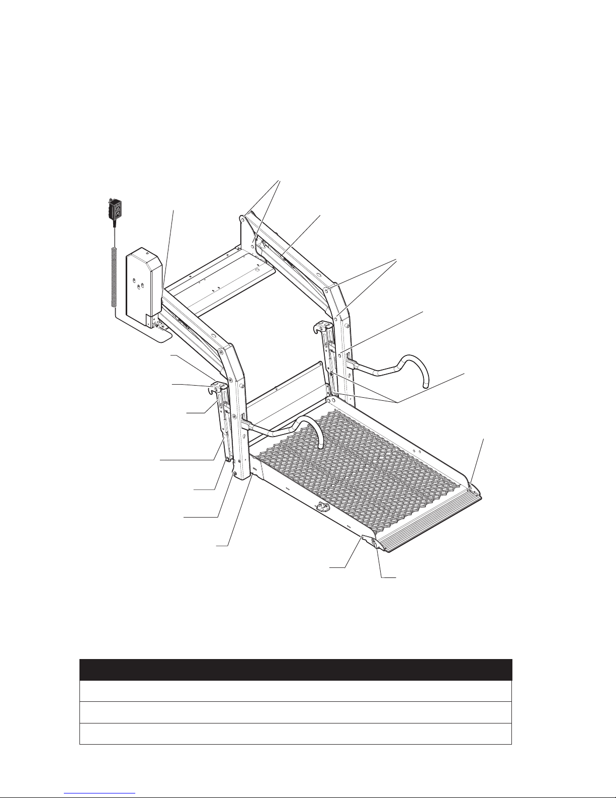
Lift Terminology
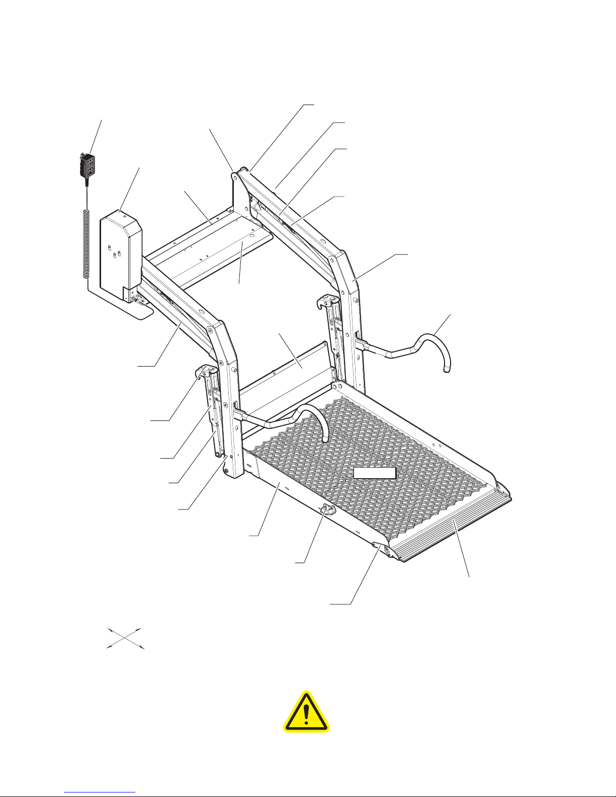
BraunAbility wheelchair lifts provide a
method of boarding and exiting applicable
motor vehicles. BraunAbility wheelchair
lifts accommodate wheelchair passengers,
standees, and other mobility aid users.
The lift must be installed, operated,
and maintained as detailed in this
manual. Any use of equipment
other than instructed in this manual
is prohibited.
36453
36454
Pump Module
(Left)
Hand-Held
Pendant
Control
Base Plate
Base Plate Cover
Top Parallel Arms (2)
Main Cylinders (2)
Opposite Pump Side
Vertical Arm
Handrails (2)
Outer Barrier
Pump Side Vertical Arm
Bottom Parallel
Arms (2)
Lift-Tite™Latches (2)
Unfold Assist Compression Springs (2)
Latch Foot (2)
Platform
Towers (2)
Inner Roll Stop
Saddle (2)
Outer Fold Arm (2)
Inner Fold Arm (2)
Platform Side Plates (2)
Stow Bumper Bracket (2)
Outboard
Right (Front)
Left (Rear)
Inboard
Page 8
Page 11
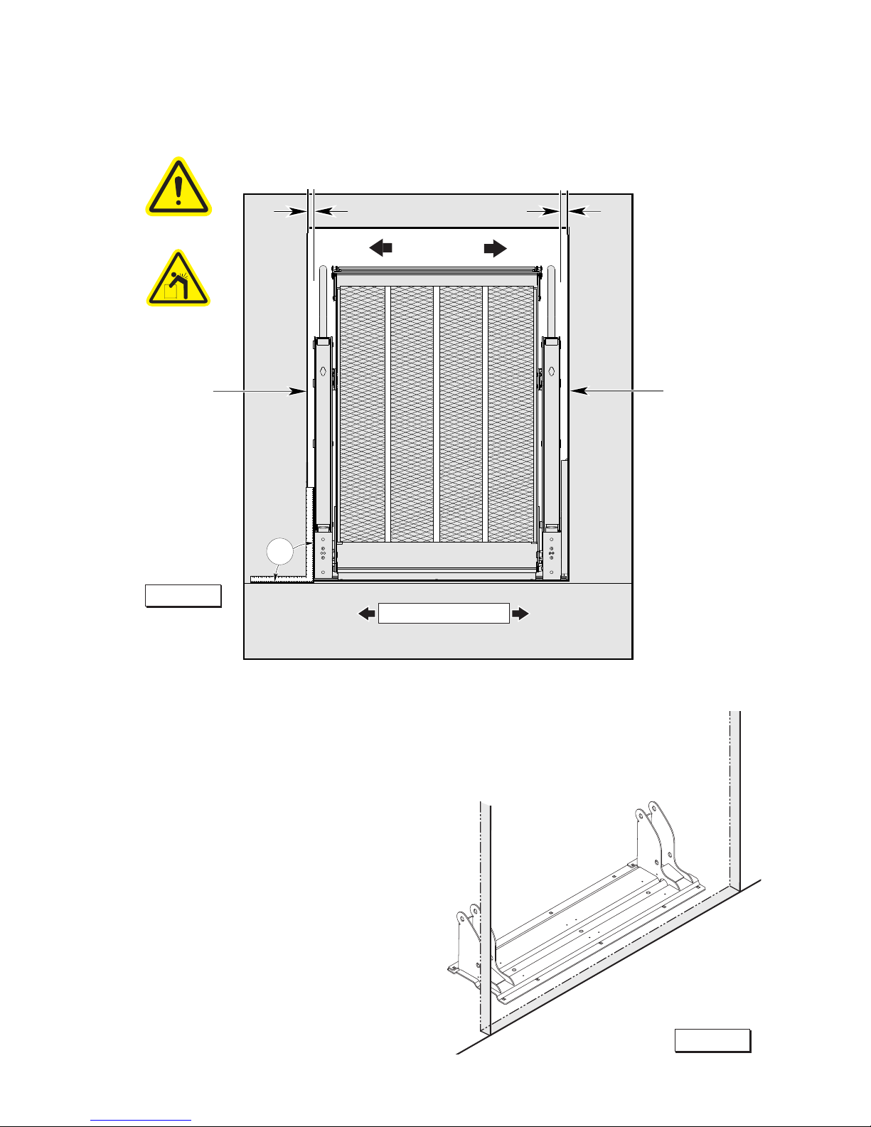
90
90
Center lift in
door opening.
Lift Installation
Lift towers and
vertical arms must
be parallel (aligned)
with vertical sides
of door jamb and
perpendicular (90˚)
to the vehicle oor.
Position Lift
Align
(Parallel)
Vertical Arm
must clear
door opening.
Side to Side Alignment
Align
(Parallel)
Figure A
Clearance:
Center the lift in the opening. See Figure A.
Position the base plate parallel to (aligned
with) the door opening as shown in Figure B.
Close the vehicle door(s).
Position lift as close to the door opening
as possible while maintaining a minimum
clearance of 12 mm between the lift and the
door or wall. See Figure C.
Lift-Tite® Latches: When checking vehicle
wall clearance - allow the lift to drift fully into
the Lift-Tite® latches to ensure clearance
(should drift occur). See Figure D. Using the
hand pump handle, stroke the hand pump to
stow the lift fully. Then open the valve slightly
(1/2 turn only), and allow the Lift-Tite® latches
to engage the vertical arm pins fully. Close
pump valve.
Align Base Plate with Door Opening
Vertical Arm
must clear
door opening.
DOOR OPENING
Page 9
Figure B
Page 12
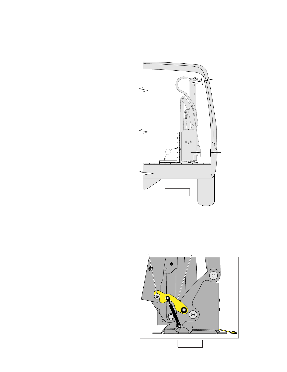
90°
Lift Installation
Position Lift
Minimum
12 mm
Clearance
Minimum
12 mm
Clearance
Figure C
Alignment:
Side-to-Side Alignment: See Figure A
on previous page. The lift vertical arms
and platform should be perpendicular
(90°) to the vehicle oor and parallel
(aligned) with the vertical sides of door
jamb. The vertical arms and the parallel
arms must clear the door opening when
the lift folds and unfolds.
Inboard-to-Outboard Alignment: See
Figure C. The vertical arms and parallel arms must be aligned and parallel to
each other. The lift towers should be
perpendicular (90°) to the vehicle oor.
Step well Installations: It is not permissible for the base plate to overhang
the step well. Base plate support must
be constructed in the step well for lift
support. The structure must be level
with the existing oor and of equivalent
construction (structural strength).
Lift-Tite® Latches: When checking
vehicle wall clearance - allow the lift to
drift fully into the Lift-Tite® latches to
ensure proper clearances.
Lift-Tite® Latch
Engagement Pin
Figure D
Page 10
Page 13
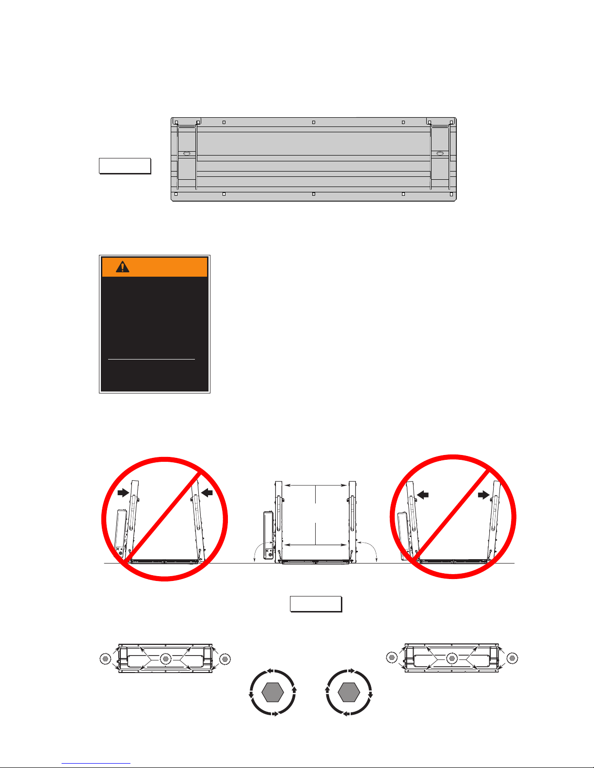
7 6
1
4
5
8
1. Drill two mounting holes
(holes 6 and 7).
2. Temporarily secure lift using
two mounting bolts (holes 6
and 7).
3. Manually deploy lift and
check lift clearance. Drill
remaining mounting holes.
4. Install below oor mounting
hardware per instructions
supplied in kit.
5. Install remaining mounting
bolts.
6. Tighten mounting bolts 1
through 8 per sequence
detailed above. Note
deection detail below.
Mounting Bolt Torque
Target: 40 Nm.
3
2
Secure lift
Figure E
Lift Installation
Figure F
Dimensions
MUST
be Equal
90˚
90˚
To Correct:To Correct:
T
I
G
H
T
E
N
L
O
O
S
E
N
L
O
O
S
E
N
L
O
O
S
E
N
T
I
G
H
T
E
N
T
I
G
H
T
E
N
L
O
O
S
E
N
T
I
G
H
T
E
N
LoosenTighten Tighten TightenLoosen Loosen
Dimensions
MUST
be Equal
90˚
90˚
Page 11
W
A
RNING
Check for obstructions such as gas
lines, wires, exhaust,
etc. before drilling
or cutting. Failure to
do so may result in
serious bodily injury
and/or property
damage.
Page 14
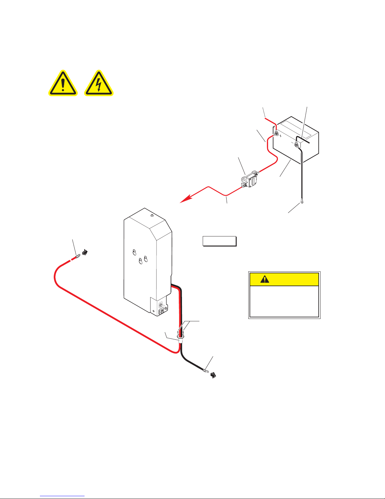
Floor Grommet:
1. Drill 28.5mm diameter grommet access hole.
Check under the vehicle for obstructions.
2. Insert grommet. Secure grommet with two
self-tap screws.
3. Route ground and power cables through
grommet. Route cables clear of exhaust,
other hot areas and moving parts.
4. Connect ground and power cables.
Lift Installation
Power Cable and Ground Cable
36513
Page 12
Pump Ground Cable:
Route the pump mounted cable through the oor
grommet and connect to a vehicle framing member as shown. See Figure H.
Vehicle Battery Ground Cable:
A 4 gauge (21.1mm2) ground cable must be connected from vehicle battery negative post to the
same vehicle framing member the pump ground
cable is attached to. See Figure H.
Ground Cable Corrosion: When mounting
ground cables, remove undercoating, dirt, rust,
etc. from framing member around mounting
holes (minimum 16mm diameter area). Apply
protective coating to mounting holes to prevent
corrosion. Failure to do so will void warranty of
certain electrical components.
C
A
UTION
Position and secure
ground cable clear of
lift operation.
Floor
Grommet
Ground Cable
to Chassis
Power (Battery)
Cable to Circuit
Protection Device
Self-tap
Screws
Aux.
TO
LIFT
Bat.
Pos.
Neg.
Aux.
Bat.
Bat.
Pos.
Neg.
Aux.
TO
LIFT
Circuit
Protection
Device
Lead Cable
OEM (+) Cable
Ground Cable
to Chassis
4 Gauge
(21.1mm2)
(not supplied)
Vehicle
Battery
OEM (-) Cable
Power Cable
Figure G
Page 15
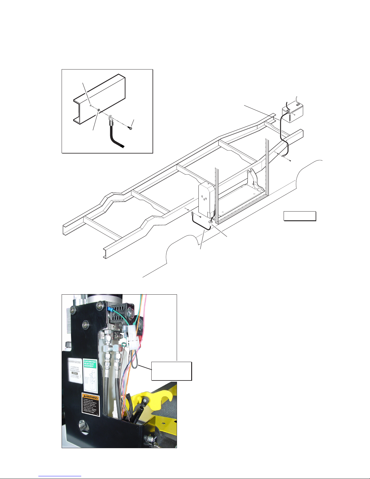
Vehicle Battery Positive Cable:
Install in-line circuit protection device
as shown in Figure G. Attach power
cable and lead cable as shown.
Interlock Instructions EU:
The lift shall be installed in such way
that the lift cannot be operational
unless the vehicle is immobilized.
Install a microswitch to the hand brake
that provides signal when the hand
brake is engaged (installer provided).
Verify that the lift is not operational
unless the hand brake is engaged.
The E-Series pump module is
equipped with 2-conductor jumper
wire that is available for interlock (see
photo at left). See service manual
electrical schematic also.
Lift Installation
Power Cable and Ground Cable
Page 13
Ground Cable
Mounting Hardware Detail
2-Conductor
Jumper Wire
Chassis
5/16-18 x 3/4”
Thread Cutting
Screw
9/32” Diameter
Pilot Hole
5/16”
External Tooth
Star Washer
DOOR OPENING
Lift Base Plate
NEG.
POS.
Battery
Chassis
Pump
Module
Battery to Frame
Ground Cable
4 Gauge (21.1mm2)
(not supplied)
Pump Mounted
Ground Cable
4 Gauge (21.1mm2)
Grommet
Figure H
Page 16
Lift Installation
Platform Angle Adjustment
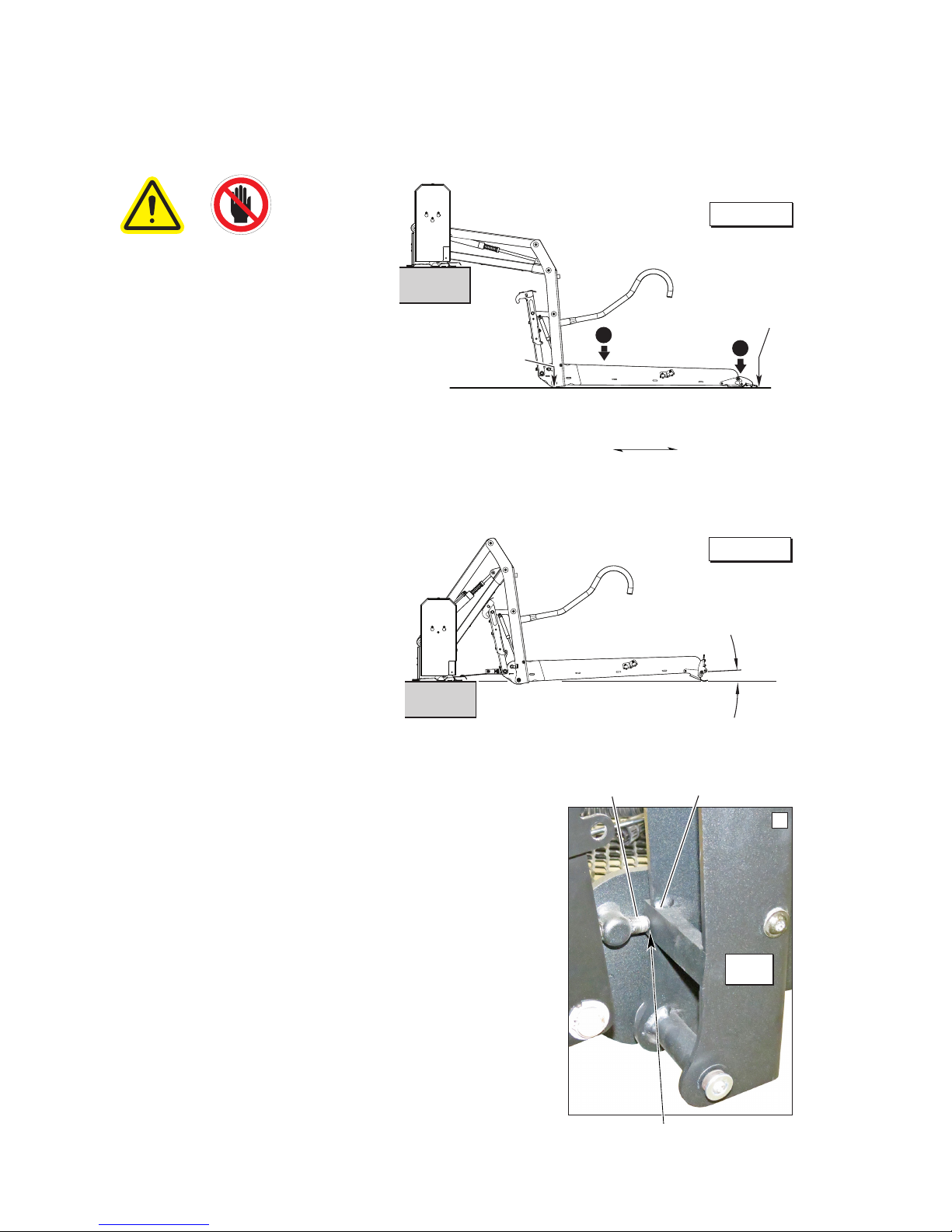
Floor Level Adjustment:
Following platform angle
adjustment, set platform
oor level positioning
as detailed in Tower
Microswitch Adjustment.
Check platform angle
again after performing
Tower Microswitch
Adjustment procedures.
Lowering Sequence Requirements
1. The outboard end (toe) of
the platform must contact
the ground rst to ensure
the spring-loaded outer
barrier unfolds fully. See
Figure I.
2. The inboard end (heel) of
the platform must lower fully
(vertical arms must contact
ground when fully lowered).
See Figure I.
The angle of the platform at
ground level directly affects
the angle of the platform when
positioned at oor level.
Raise the platform to oor
level. Note the angle of the
platform.
The platform at oor level
should have a slight upward
angle as shown in Figure J.
Adjust platform angle as detailed below.
(Heel) Inboard
Outboard (Toe)
Heel
Ground Level
Barrier must
unfold fully.
Platform heel
must lower fully.
Barrier
Floor
Level
2
1
Adjustment Procedure:
Platform angle adjustment
Allen screws are provided
on each side of the platform
(see photo at right).
Turn adjustment screws
clockwise to raise the outboard end of the platform.
Turn adjustment screws
counterclockwise to lower the
outboard end of the platform.
Both adjustment screws must
make full contact with the
stop block bars in the vertical
arms (see Photo A at right).
Adjustment screws must make
full contact on both sides.
36514
Vertical
Arm
A
Adjustment
Screw
Stop Bar
Page 14
Figure J
Figure I
Page 17
25 mm (1 in)
Minimum
Overlap
Lift Installation
Tower Microswitch Adjustment
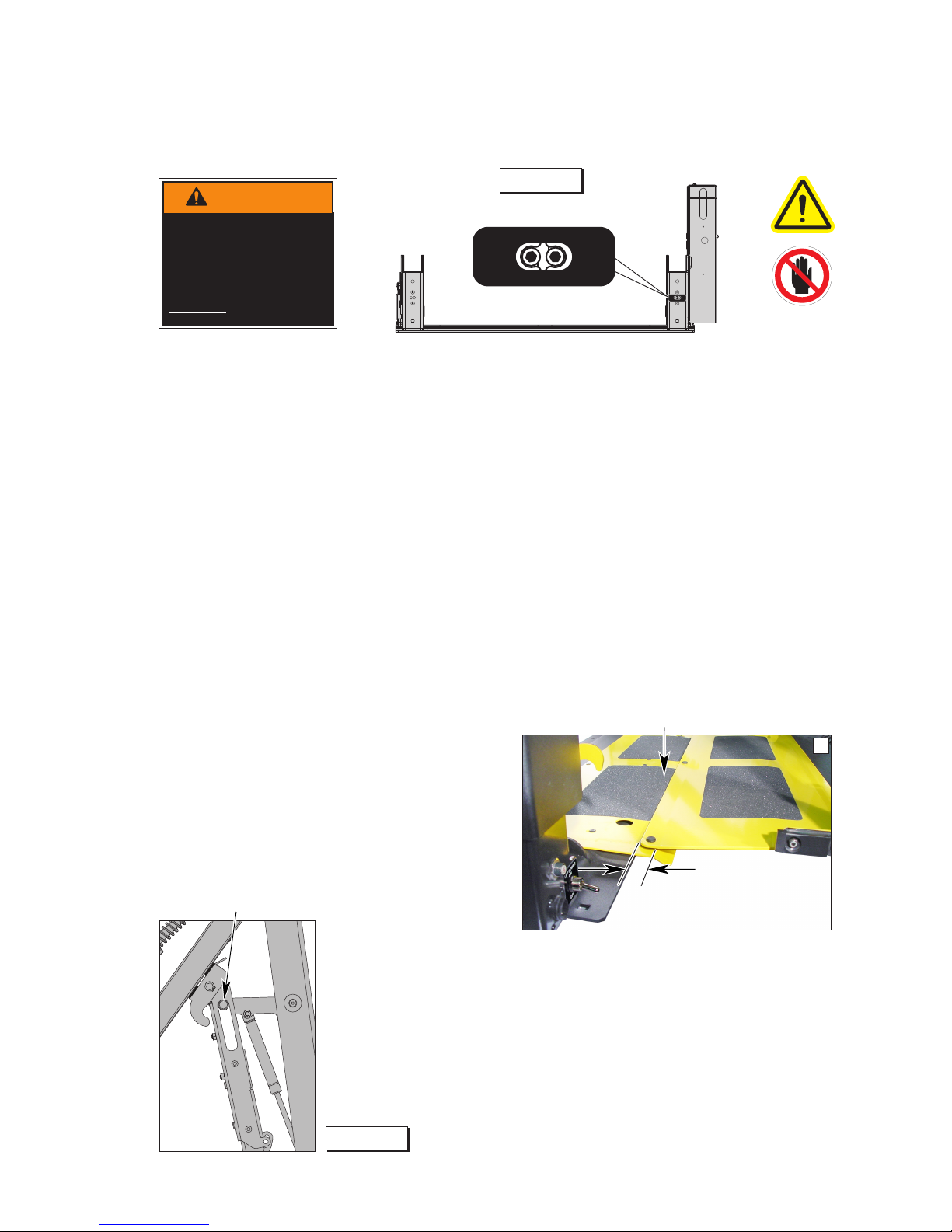
Review adjustment
procedures below and
adjust as needed only.
Left (rear) pump lift depicted. Right
(front) pump lift is a mirrored image.
36514
Tower 1 (Unfold) Switch Adjustment
Floor Position from Stow
1. Position platform at the fully stowed position using the manual hand pump or pendant
control.
2. Turn switch adjustment screw clockwise 3 full
turns.
3. Press pendant UNFOLD switch (continue
pressing switch until platform stops unfolding).
4. When platform stops unfolding, turn switch adjustment screw counterclockwise while pressing the pendant UNFOLD switch. Platform
position will change. Repeat adjustment until
criteria below is met.
Proper Adjustment Criteria:
• Handrail pin should be at the top of the slot in
outer fold arm. See Figure L.
• Bridge plate should rest on base plate cover
and should overlap a minimum 25 mm (1 in).
See Photo B.
• Both platform angle adjustment Allen screws
are making full contact with vertical arm stop
block bars. See Photo A.
Tower 2 (Up) Switch Adjustment
Floor Position from Below Floor
1. Lower platform a minimum of 15.25 cm
below oor level position using the manual
hand pump or pendant control.
2. Turn switch adjustment screw counterclockwise 3 full turns.
3. Press pendant UP switch (continue pressing switch until platform stops).
4. When platform stops, turn switch adjustment screw clockwise while pressing the
pendant UP switch. Platform position will
change. Adjust platform to meet criteria
listed for Tower 1 Switch "Proper Adjustment Criteria".
Handrail pin at top of slot.
TOWER2TOWER
1
32942
Partial Stow Switch
Partial Stow to Full Stow Position
The partial stow microswitch is located in
the opposite pump side tower and has no
adjustment. Switch is deactivated (unpressed) once platform has been stowed to
approximately a 45° angle. Full pressure is
activated in this position and will allow the
platform to stow securely.
TOWER
2
TOWER
1
32942
Bridge plate should rest on base plate cover.
B
Page 15
Improper microswitch
adjustment may
result in serious
bodily injury and/or
property damage.
W
A
RNING
Figure L
Figure K
Page 18

Installer Verification
Compatibility between the lift and the vehicle
The installer shall conrm the compatibility between the lift and the vehicle.
Static Test
Deformation
The unladen platform is positioned mid-way between ground level and vehicle oor level and
measurements are taken of the height of the platform and its angular attitude relative to the vehicle oor.
A load of 500 kg is applied to the platform and subsequently removed.
By repeating measurements of the height and attitude of the platform, verify that no permanent
deformation has occurred in any part of the lift or its attachment to the vehicle which could affect the
function of the lift.
Drift
A load of 500 kg is applied to the platform, positioned at oor level. Measurements are taken of the
height of the platform and its angular attitude relative to the vehicle oor. These measurements are
repeated after a 15 minute test period.
Verify that the vertical drift of the platform between the two measurements has not exceeded 15mm.
Verify that the angular drift of the platform between the two measurements has not exceeded 2º.
Test to Verify that the Lift Cannot Lift Excessive Load
A load of 440 kg is applied to the platform, positioned at ground level. Actuate the UP control and verify
that the platform does not lift (tilt is permissible).
1. Lower platform to the ground.
2. Place 440 kg at center of platform.
3. Press UP switch and verify platform does not lift (tilt is permissible).
4. If platform does not lift, proceed to Dynamic Test. If platform does lift, proceed to step 5, PLATFORM
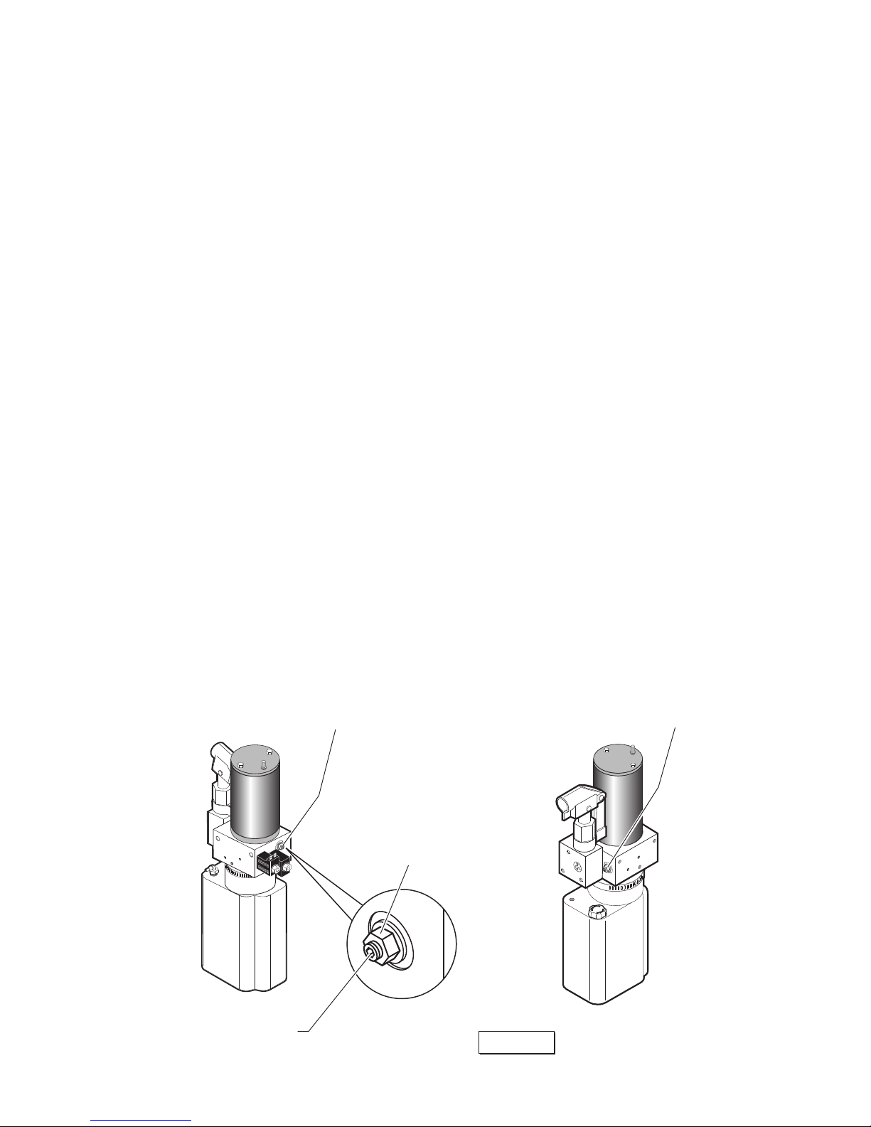
UP relief valve adjustment is necessary.
5. Access PLATFORM UP relief valve (see illustration on following page). Loosen 9/16" hex nut on the
relief valve adjustment screw (do not remove hex nut).
6. Turn adjustment screw counterclockwise 1/8 turn.
7. Press UP switch and verify platform does not lift (tilt is permissible).
8. If platform does not lift, tighten 9/16" hex nut (do not turn relief valve adjustment screw while
tightening hex nut). If platform does lift, repeat steps 6 through 8
Page 16
Page 19
Installer Verification
Dynamic Test
With 400 kg applied to the platform, verify that the lift is able to operate throughout its full range of
normal lifting and lowering.
1. Lower platform to the ground.
2. Place 400 kg at center of platform.
3. Verify lift is able to operate throughout its full range of normal lifting and lowering movements.
4. If platform is able to operate throughout its full range of normal lifting and lowering movements, no
adjustment is necessary. If platform does not lift, proceed to step 5, PLATFORM UP relief valve
adjustment is necessary.
5. Access PLATFORM UP relief valve (see Figure M). Loosen 9/16" hex nut on the relief valve
adjustment screw (do not remove hex nut).
6. Turn adjustment screw clockwise 1/8 turn.
7. Verify lift is able to operate throughout its full range of normal lifting and lowering movements.
8. If lift does not operate throughout its full range, repeat steps 6 through 8. If lift does operate
throughout its full range, tighten 9/16" hex nut (do not turn relief valve adjustment screw while
tightening hex nut).
9. Repeat the "Test to Verify that the Lift Cannot Lift Excessive Load" on previous page.
Test of Operations and Safety Functions
All functions of the lift and operations of all safety devices are veried after the static and dynamic tests
have been completed. These tests do not apply to pipe break valves nor non-resettable safety devices
such as electrical fuses (These items are the subject of a manufacturer’s type test).
Page 17
DO NOT adjust this valve!
(Located beside Backup Pump)
Platform Up Relief Valve
Adjustment Allen Screw
9/16"
Hex Nut
Note: Secure adjustment
screw and tighten hex
nut following adjustment.
Figure M
Page 20
Page 18
Lift Operation Safety
SAFETY FIRST! Know That ....
The information contained in
this manual and supplements (if
included), is provided for your
use and safety. Familiarity with
proper installation, operation,
maintenance and service procedures is necessary to ensure
safe, trouble-free lift operation.
Safety precautions are provided
to identify potentially hazardous
situations and provide instruction on how to avoid them.
Safety Symbols
This symbol indicates
important information
regarding how to
avoid a hazardous
situation that could
result in minor personal injury or property
damage.
C
A
UTION
These symbols will appear throughout this manual as well as on the labels posted on your lift.
Recognize the seriousness of this information.
This symbol indicates a device weighs in excess of 139kg (306 lbs).
Use of a fork lift or hoist is required.
This symbol indicates the presence of a re hazard. Avoid open ames or
sparks when working with ammable materials to prevent injury or damage.
This symbol indicates the presence of high pressure hydraulic hoses. Use
appropriate personal protective equipment when working on hydraulic system.
This symbol indicates an area to avoid bodily contact to prevent injury.
36514
This symbol indicates that a condition where injury or damage could occur if
contact is made with the hot surface.
36512
This symbol indicates that a condition where damage to the equipment resulting
in injury to the operator could occur if operational procedures are not followed. To
reduce the risk of damage or injury, refer to accompanying documents, follow all
steps or procedures as instructed.
This symbol indicates that there are dangerous energy levels present inside the
enclosure of this product. To reduce the risk of re or electric shock, do not attempt
to open the enclosure or gain access to areas where you are not instructed to do
so. Refer servicing to qualied service personnel only.
36513
Additional information provided to help clarify or detail a specic subject.
NOTICE
This symbol indicates
important safety information regarding a
potentially hazardous
situation that could
result in serious bodily
injury and/or property
damage.
W
A
RNING
Page 21
Page 19
Lift Operation Safety
Lift Operation Safety Precautions
W
A
RNING
If the lift operating
instructions, manual
operating instructions
and/or lift operation
safety precautions are
not fully understood,
contact BraunAbility
immediately. Failure
to do so may result in
serious bodily injury
and/or property damage.
Read manual and supplement(s) before operating lift.
Read and become familiar with all safety precautions,
operation notes and details, operating instructions and
manual operating instructions before operating the lift.
Load and unload on level surface only.
Engage vehicle parking brake before operating lift.
Provide adequate clearance outside the vehicle to accommodate the lift before opening lift door(s) or operating lift.
Inspect lift before operation. Do not operate lift if you
suspect lift damage, wear or any abnormal condition.
Do not use as a link bridge.
Keep operator and bystanders clear of area in which the lift operates.
Lift attendant must observe passenger at all times during lift operation.
Ensure adequate lighting exists in the lift operating area.
Whenever a wheelchair passenger (or standee) is on the platform, the:
• Passenger must be positioned fully inside yellow boundaries facing outward.
• Wheelchair brakes must be locked
• Bridge plate and roll stop must be up (vertical)
• Roll Stop latch must be fully engaged
• Passenger should grip both handrails (if able).
Wheelchair lift attendants should be instructed on any special needs and/or procedures
required for safe transport of wheelchair passengers.
Load and unload clear of vehicular trafc.
Do not attempt to load or unload a passenger in a wheelchair or other apparatus that
does not t on the platform area.
The lift attendant shall not ride on the platform with the passenger. The lift is intended
for use by a single passenger.
Do not overload or abuse. The load rating applies to both the raising and lowering
functions.
Use caution when operating this equipment out of doors during electrical storms or
similar electrical phenomena.
Use caution when operating this equipment in severe weather or environmental
conditions (fog, rain, snow, ice, dust, etc.)
Discontinue lift use immediately if any lift or vehicle interlock does not operate properly.
Do not operate or board the lift if you or your lift operator are intoxicated.
Page 22
Page 20
Lift Operation Safety
Lift Operation Safety Precautions
Do not raise front wheelchair wheels (pull wheelie) when loading, boarding, or riding on
the platform.
Open lift door(s) fully and secure before operating lift.
Position and secure (buckle, engage, fasten, etc.) the wheelchair-equipped occupant
seat belt (torso restraint) before loading onto the wheelchair lift platform.
Lift attendants must ensure that lift occupants keep hands, arms and all other body
parts within the lift occupant area and clear of moving parts.
Platform must be positioned at oor level (bridging position) when loading or unloading
in and out of vehicle.
Do not use platform bridge plate or roll stop as a brake. Stop and brake wheelchair
when loading onto the platform (manually stop and brake manual wheelchairs — stop
powered wheelchairs with the wheelchair controls).
Turn powered (electric) wheelchairs off when on lift platform.
Press the DOWN switch until the entire platform rests on ground level (lowered
fully) and the roll stop is fully unfolded (ramp position) before loading or unloading a
passenger at ground level.
Roll stop must be fully unfolded (ramp position) until front and rear wheelchair wheels
cross the barrier when loading or unloading at ground level.
Accidental activation of control switch(es) may cause unintended operation(s).
Maintenance and lubrication procedures must be performed as specied in this manual
by authorized (certied) service personnel.
Replace missing, worn or illegible decals.
Never modify (alter) a BraunAbility lift.
Do not use accessory devices not authorized by BraunAbility.
Do not remove any guards or covers.
Keep clear of any hydraulic leak.
Failure to follow these safety precautions may result in serious bodily injury and/or
property damage.
Page 23
Before lift operation, park the
vehicle on a level surface,
away from trafc. Place the
vehicle transmission in “Park”
and engage the parking brake.
Vehicle engine must be running.
Lift Operating Instructions
address operation of the lift only.
Vehicle Doors and Vehicle
Interlocks: Transit vehicle
lift doors and interlocks vary.
Procedures to operate them
vary also. Lift operators
(attendants) must become
familiar with the vehicle lift
access door system and vehicle
interlock(s).
Manual Door(s): Open manual
doors fully and secure in full
open position before operating
the lift.
Do not operate the lift if you
suspect lift damage, wear, or any
abnormal condition. Refer to the
Manual Operating Instructions to
manually operate lift.
Lift Operating Instructions
36514
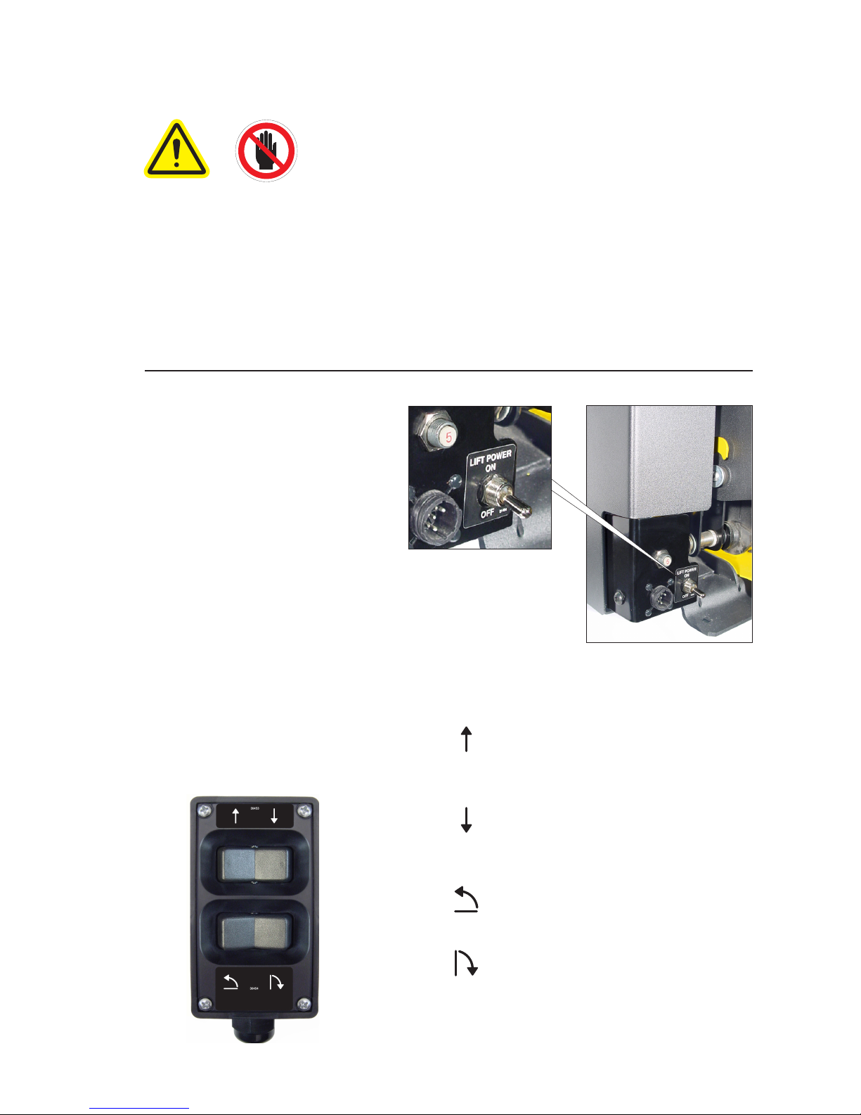
Lift Power ON/OFF Switch: This
switch must be in the ON position
in order to activate the lift.
Hand-held Pendant Control: The hand-held
attendant’s pendant control is equipped with
two rocker switches.
UP: From ground level, the UP function
will raise (rotate) the roll stop to the vertical
position. The platform then raises to oor
level position.
DOWN: From oor level, the DOWN function lowers the platform to ground level and
then unfolds (lowers) the roll stop to the
ramp (horizontal) position.
FOLD: From oor level, the FOLD func-
tion folds the platform inward to the stowed
position.
UNFOLD: From stowed position, the UNFOLD function unfolds the platform outward
to the oor position.
Note: If any functions do not occur as
described, discontinue lift use immediately.
Control Switch Functions:
Hand-held
Pendant Control
Lift Power On/Off Switch
Page 21
Page 24
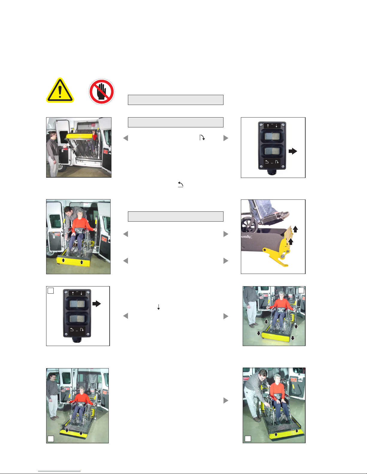
Lift Operating Instructions
D
C
Before lift operation, park on
a level surface, away from ve-
hicular trafc. Place the vehicle
transmission in “Park” and engage the parking brake. Vehicle
engine must be running. Refer
to the Manual Operating Instructions to manually operate lift.
B
A
2. Press DOWN switch until
the entire platform reaches
ground level (see Photo B)
and the roll stop unfolds fully
(ramp position). See Photo C.
Release switch.
3. Unlock wheelchair brakes
and unload passenger from
platform.
OPEN DOOR(S) AND SECURE
TO UNFOLD PLATFORM:
Stand clear and press the
UNFOLD switch until the
platform stops (reaches oor
level - unfolds fully). Release
switch.
Notice: In event platform does
not unfold, press FOLD
switch to release Lift-Tite™
latches.
TO UNLOAD PASSENGER:
1. Read Notice below! Load
passenger onto platform and
lock wheelchair brakes.
Notice: Passenger must be
positioned fully inside yellow
boundaries, and roll stop must
be UP.
36514
Page 22
Page 25
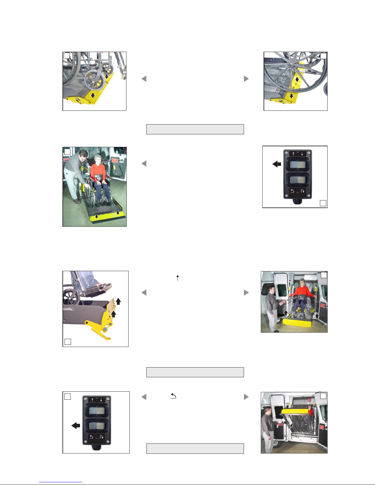
Lift Operating Instructions
L
K
F
E
Notice: Roll stop must be
fully unfolded (ramp position)
until the entire wheelchair (or
standee) has crossed the roll
stop. See Photos E and F.
H
G
TO LOAD PASSENGER:
1. Read Notices below! Load
passenger onto platform and
lock wheelchair brakes. See
Photo G.
Notice: Roll stop must be
fully unfolded (ramp position)
until the entire wheelchair (or
standee) has crossed the roll
stop. See Photos E and F.
Notice: Passenger must be
positioned fully inside yellow
boundaries.
J
2. Press UP switch (Photo H)
to fold roll stop UP fully (vertical - see Photo I), and raise
the platform to oor level.
See Photo J. Release switch.
3. Unlock wheelchair brakes
and unload passenger from
platform.
TO FOLD PLATFORM:
Press FOLD (In) switch until
platform stops (fully folded).
See Photos K and L. Release
switch
CLOSE DOOR(S)
Page 23
I
Page 26
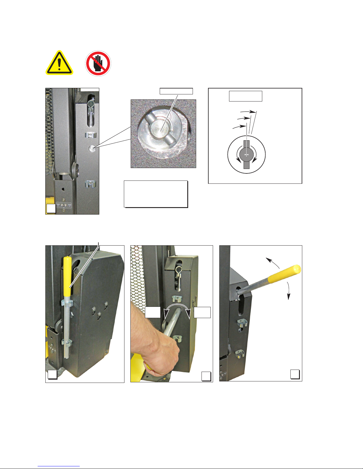
Notice: Bridge plate and roll stop automatically
function during manual operations.
Hand Pump Handle
Notice: Close backup
pump release valve
securely before operating
electric pump.
Manual Operating Instructions
36514
A
B
Open
(Down)
Close
(Up/Stop)
C
D
Release Valve
Page 24
Release Valve
maximum
3 Nm
minimum
2 Nm
seats
(stops)
approximate
1.5 mm intervals
Valve Tightening
Specication:
Once valve seats
(stops), tighten 2
to 3 Nm as shown.
O
P
E
N
C
L
O
S
E
Page 27
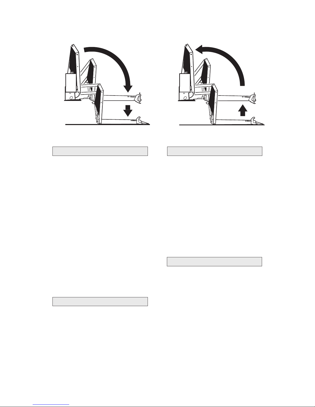
To Unfold Platform (Out):
Using hand pump handle (Photo B):
1. Close hand pump valve (place slotted
end of pump handle onto release valve
and turn clockwise). See Photo C.
2. Insert handle in pump and stroke until
platform folds fully (stops). See Photo D.
3. Open hand pump valve (turn counter-
clockwise) until platform reaches oor
level. Open 1/4 turn only.
4. Close hand pump valve (turn clockwise).
Notice: Valve must be tight, but do not
overtighten.
Place slotted end of pump handle onto
release valve and turn counterclockwise
(open 1/4 turn only) until the platform
reaches ground level and the roll stop
unfolds. See Photo C.
Down (To Lower):
Using hand pump handle:
a. Place slotted end of pump handle onto
release valve and turn clockwise to close
securely. See Photo C.
Notice: Valve must be tight, but do not
overtighten.
b. Insert handle into back-up pump and
stroke until platform reaches oor level
(see Photo D).
To Fold Platform (In):
Insert handle in pump and stroke until platform stops (folds fully). See Photo D.
Notice: Close release valve securely before
operating electric pump. Store pump handle
in clamps shown in Photo B.
Up (To Raise):
Manual Operating Instructions
Page 25
Page 28
36453
36454
Maintenance and Lubrication
Specied(recommended) Available Braun
Lubricant Type Lubricant Amount Part No.
LO - Light Oil
LG - Light Grease
Light Grease Lubriplate 14 oz.
(Multipurpose) Can
Light Penetrating Oil LPS2, General Purpose 11 oz.
(30 weight or equivalent) Penetrating Oil Aerosol Can
Stainless Stick Door-Ease 1.68 oz.
Style (tube) Stick (tube)
DE - Door-Ease
15807
15806
15805
See the Maintenance/Lubrication Schedule for recommended applications per number of cycles.
Handrail Pivot Pins (2)
LO
Lift-Tite™ Latch Tower Pivot Points
(2 Latches - 2 Points)
and
Lift-Tite™ Latch Dampening Spring
(2 springs - 4 Points)
LO
Inner Roll Stop Lever
Bearings (2) and Slots (2)
LO
Outer Barrier
Arm Slots (2)
LG
Outer Barrier
Latch Foot Bearings (2)
LO
Platform Pivot Pin Bearings (4)
LO
Inner Fold Arm Bearings (8)
LO
Saddle Bearing Buttons (4)
DE
Saddle Pivot Points (4)
LO
Outer Barrier
Pivot Pin Bearings (2)
LO
Inner and Outer Fold Arm
Telescoping Area
LG
Hydraulic Cylinder
Pivot Bushings (8)
LO
Lift-Tite™ Latch Rollers (2)
LO
Parallel Arm
Pivot Pin Bearings (16)
LO
Parallel Arm
Pivot Pin Bearings (16)
LO
Outer Roll Stop Slide Slots (2)
LG
Page 26
Lubrication Diagram
Page 29
Maintenance and Lubrication Schedule
Outer barrier pivot pin bearings (2)
Outer barrier latch foot bearings (2)
Outer barrier arm slots (2)
Lift-Tite™ latches (tower pivot points - 2)
Lift-Tite™ latch gas (dampening) spring pivot
points (2 springs - 4 points)
Inspect Lift-Tite™ latches and gas springs
for wear or damage (bent, deformed or misaligned), positive securement (external snap
rings) and proper operation
Lift-Tite™ latch rollers (2)
Inspect outer barrier for proper operation
Apply Light Oil - See Lubrication Diagram
Apply Light Oil - See Lubrication Diagram
Apply Light Grease - See Lubrication Diagram
Apply Light Oil - See Lubrication Diagram
Apply Light Oil - See Lubrication Diagram
Resecure, replace damaged parts or otherwise
correct as needed. Note: Apply Light Grease to
Lift-Tite™ latch tower pivot point if replacing latch.
Apply Light Oil - See Lubrication Diagram
Correct or replace damaged parts.
750
Cycles
continued
Proper maintenance is necessary to ensure
safe, trouble-free lift operation. Inspecting the lift
for any wear, damage or other abnormal conditions should be a part of the transit agency daily
service program. Simple inspections can detect
potential problems.
Park vehicle on a level surface clear of trafc
and bystanders. Place vehicle transmission in
“Park” and engage parking brake. Deploy lift
to ground level. Provide adequate work space
around fully-deployed lift. Perform specied
maintenance and lubrication procedures (position lift as required).
Pump Module: When cleaning the exterior of
the pump module, rst disconnect the unit from
its power source. Do not use liquid cleaners,
aerosols, abrasive pads, scouring powders or
solvents, such as benzine or alcohol. Use a
soft cloth lightly moistened with a mild detergent
solution. Ensure the surface cleaned is fully dry
before reconnecting power.
Other Components: Clean components and
the surrounding area before applying lubricants.
Clean only with mild detergent and water. Do
not clean with solvents. Allow the lift to dry thor-
oughly and apply lubricants as specied after
every cleaning.
LPS2 General Purpose Penetrating Oil is recommended where Light Oil is called out. Use
of improper lubricants can attract dirt or other
contaminants which
could result in wear
or damage to components. Platform
components exposed to contaminants when lowered
to the ground may
require extra attention.
Perform maintenance and lubrication procedures
at the scheduled
intervals according to the number of cycles. When
servicing the lift at the recommended intervals,
inspection and lubrication procedures specied in
the previous sections should be repeated.
These intervals are a general guideline for scheduling maintenance procedures and will vary according to lift use and conditions. Lifts exposed
to severe conditions (weather, environment,
contamination, heavy usage, etc.) may require
inspection and maintenance procedures to be
performed more often than specied. Records of
maintenance and service procedures should be
maintained.
Discontinue lift use if maintenance and lubrication
procedures are not properly performed, or if there
is any sign of wear, damage or any abnormal condition. Contact your authorized representative.
36513
36514
36512
Page 27
W
A
RNING
Maintenance and
lubrication procedures
must be performed as
speciedbyan
authorized service
technician. Failure to
do so may result in
serious bodily injury
and/or property
damage.
Page 30
Maintenance and Lubrication Schedule
Inner/Outer fold arm contact areas (2)
Platform pivot pin bearings (4)
Inner fold arm pivot points (2)
Outer fold arm pivot points (2)
Inner roll stop lever bearings (2)
Inner roll stop lever slots (2)
Saddle pivot points (4)
Parallel arm pivot pin bearings (16)
Handrail pivot pins (2)
Hydraulic cylinder pivot bushings (8)
Inspect inner roll stop for:
• Wear or damage
• Proper operation. Inner roll stop should just
rest on top surface of the base plate.
• Positive securement (both ends)
Inspect handrail components for wear or damage, and for proper operation
Inspect microswitches for securement and
proper adjustment.
Make sure lift operates smoothly
Inspect external snap rings:
• Inner fold arm pivot pins (2)
• Outer fold arm pivot pins (2)
• Inner roll stop levers (4)
• Lift-Tite™ latch gas (dampening) springs (4)
• Lift-Tite™ latch pivot pins (2)
Remove pump module cover and inspect:
• Hydraulic hoses, ttings and connections for
wear or leaks
• Harness cables, wires, terminals and connec-
tions for securement or damage
• Circuit breaker, power switch and solenoids
for securement or damage
Apply Grease (Synthetic) to contact areas
between upper/lower fold arms. See
Lubrication Diagram
Apply Light Oil - See Lubrication Diagram
Apply Light Oil - See Lubrication Diagram
Apply Light Oil - See Lubrication Diagram
Apply Light Oil - See Lubrication Diagram
Apply Light Oil - See Lubrication Diagram
Apply Light Oil - See Lubrication Diagram
Apply Light Oil - See Lubrication Diagram
Apply Light Oil - See Lubrication Diagram
Apply Light Oil - See Lubrication Diagram
Resecure, replace or correct as needed.
See Platform Angle Instructions and Platform Floor Level Microswitch Adjustment
Instructions.
Replace damaged parts.
Resecure, replace or adjust as needed.
See Tower Microswitch Adjustment Instructions.
Realign towers and vertical arms. Lubricate or correct as needed.
Resecure or replace if needed.
Resecure, replace or correct as needed.
Inspect outer barrier latch feet for proper operation, positive securement and detached or missing
torsion springs
Inspect lift for wear, damage or any abnormal
condition
Inspect lift for rattles
Correct, replace damaged parts and/or
relubricate
Correct as needed.
Correct as needed.
Perform all procedures listed in previous section also
750
Cycles
1500
Cycles
Page 28
Page 31
Maintenance and Lubrication Schedule
Use Braun 32840-QT (Exxon® Univis HVI 26)
hydraulic uid (do not mix with Dextron III
or other hydraulic uids). Check uid level
with platform lowered fully and roll stop
unfolded fully. Fill to within 1/2" of the bot-
tom of the 1-1/2" ll tube (neck).
Tighten, repair or replace if needed.
Replace if needed.
Tighten or replace if needed.
Replace damaged parts and resecure as
needed. Apply Light Grease during reassembly procedures.
Replace damaged parts and relubricate if
needed
Replace if needed.
Tighten, replace or correct as needed
Apply Door-Ease or replace if needed. See
Lubrication Diagram.
Resecure or replace if needed.
Resecure, repair or replace if needed.
Check to see that the lift is securely anchored to the vehicle and there are no loose
bolts, broken welds, or stress fractures.
Replace decals if worn, missing or illegible.
Replace antiskid if worn or missing.
Perform all procedures listed in previous section also
Repeat all previously listed inspection,
lubrication and maintenance procedures
at 750 cycle intervals.
Consecutive
750 Cycle
Intervals
4500
Cycles
Hydraulic Fluid (Pump) - Check level.
Note: Fluid should be changed if there is
visible contamination. Inspect the hydraulic
system (cylinder, hoses, ttings, seals, etc.)
for leaks if uid level is low.
Inspect cylinders, ttings and hydraulic con-
nections for wear, damage or leaks
Inspect parallel arms, bearings and pivot
pins for visible wear or damage
Inspect parallel arm pivot pin mounting
screws (8)
Inspect platform pivot pins, bearings and
vertical arms for wear, damage and positive
securement
Inspect vertical arms, handrails and pivot
pins for visible wear or damage
Inspect upper/lower fold arms, saddle,
saddle support and associated pivot pins,
bushings, and bearings for visible wear or
damage
Inspect gas springs (cylinders - 2) for wear
or damage, proper operation and positive
securement
Inspect saddle bearing buttons (4)
Inspect saddle springs (2)
Inspect power cable
Mounting
Decals and Antiskid
Lift
Disposal
Procedure
continued
2000-53-EC
Disassembly and Disposal Guidelines
No lift components contain unacceptable amounts of lead, cadmium, mercury, or
hexavalent chromium.
1. Lower platform to ground.
Page 29
Page 32
Maintenance and Lubrication Schedule
Lift
Disposal
Procedure
2. Open pump module manual relief valve.
3. Disconnect power from lift.
4. Capture and recycle hydraulic uid.
5. Disassemble lift and recycle components.
Refer to exploded views in manual.
Page 30
Page 33
Stenkullen, 2018-06-18
Autoadapt AB
Jan M Jensen
Managing Director
Product Certificate
Autoadapt AB
Declaration of Conformity
Issued by Autoadapt Safety Centre in Stenkullen, Sweden.
Manufacturer: The Braun Corporation
Address: 631 West 11th Street, Winamac, IN 46996 United States
Authorized Representative
and Importer into EU:
Manufacturer: Autoadapt AB
Address: Åkerivägen 7, 443 61 Stenkullen, Sweden
Telephone: +46 302 254 00
E-mail: [email protected]
Internet: www.autoadapt.com
Declares that the Product:
Product name: Braun Double Parallel Arm lift
Model: All versions 12/24 volts system
Conforms to the following Directives, Standards and Regulations
2006/42
ECE R-10
ECE R-17
EN 1756-2:2004 + A1 2009
EN 50489: 2010
ISO EN 12100-1/2
ISO 7637-2: 2011
CISPR 25:2008
ECE R-107 Rev. 5
EN 60204
ISO 14121-2: 2012
EN 11202
REACH
GADSL
RoHS
Page 31
Page 34
International
Inboard Lift
Public Use
Wheelchair Lifts
Solid Platform
Owner Manual
Manufacturing Revision Level: Rev. A
E Series
BraunAbility® Limited Warranty
Consult your local BraunAbility® dealer regarding warranty policy.
www.braunability.com/international
AU Designs Registered and Pending
403906 Rev. B
January
2019
Braun® is a registered trademark of BraunAbility®
Original Instructions
ISO 9001:2015
www.braunability.com/international
631 West 11th Street, Winamac, IN 46996, USA
Phone: +1 574 946 6153 Fax: +1 574 946 4670
All illustrations, descriptions and specications in this document are based on the latest product information available
at the time of publication. The Braun Corporation reserves the right to make changes at any time without notice.
 Loading...