

Page 1
Perfusor
Instructions for use
Version 1.0 English
Valid for software 002A
®
compact
plus
Page 2

Page 3

Table of Contents
1 About this document .......................................... 5
1.1 Purpose ....................................................................... 5
1.2 Signs, symbols and tags ..................................... 5
1.3 Warnings ................................................................... 6
1.4 Abbreviations .......................................................... 7
2 Symbols ...................................................................... 8
2.1 Symbols on the product and
packaging
.................................................................. 8
2.2 Symbols on the device‘sdisplay .................... 9
3 Intended use ..........................................................10
4 Safety instructions .............................................11
4.1 Safe handling ........................................................11
4.1.1 General .......................................................................11
4.1.2 Software ....................................................................11
4.1.3 Transport and storage ............................................11
4.1.4 Set-up and start-up ...............................................11
4.1.5 Stacking .....................................................................11
4.1.6 Control........................................................................12
4.1.7 Alarms and staff call ..............................................12
4.1.8 Accessories and consumables ..............................13
4.1.9 Enteral nutrition ......................................................13
4.2 Electrical connection.........................................13
4.3 Safety standards ..................................................13
5 Description of the device ................................14
5.1 Device overview ...................................................14
5.2 Interfaces ................................................................15
5.3 Display and control elements .......................16
5.4 Display overview ..................................................18
5.5 Alarm status display ..........................................18
6 Menu structure / devicefunctions ..............19
6.1 Main menu .............................................................19
6.1.1 Main menu > Rate,volume&time ...................19
6.1.2 Main menu > Drug .................................................19
6.1.3 Main menu > Dose calculation .......................... 20
6.1.4 Main menu > Settings .......................................... 20
6.1.5 Settings > Service ...................................................21
7 Set-up and powering on
7.1 Setting up and connectingthe device .... 22
7.1.1 Attach/remove the compact
stand clamp .............................................................
7.1.2 Operating the device on a stand........................ 22
7.1.3 Operating the device in the
7.1.4 Operating the device on awallrail ................... 22
7.1.5 Connecting the device to themains
7.1.6 Operating the device with abattery................. 22
plus
compact
electricity ..................................................................
station ................................................ 22
........................... 22
plus
22
22
7.2 Powering on the device on
forthefirsttime
................................................. 22
7.3 Configure device options ............................... 22
7.3.1 Turning night mode on/off .................................. 23
7.3.2 Setting display brightness ................................... 23
7.3.3 Setting the Audio Volume ................................... 23
7.3.4 Configuring the pressurealarmlimit ............... 23
7.3.5 Configuring service settings ................................24
7.4 Locking/unlocking thekeypad ..................... 25
8 Operation ............................................................... 26
8.1 Switching on the device ................................. 26
8.2 Inserting the syringe ........................................ 26
8.3 Setting the infusion values ........................... 26
8.3.1 Entering the delivery rate .................................... 26
8.4 Starting and stopping theinfusion ............27
8.5 Activating standby .............................................27
8.6 Administering bolus .......................................... 28
8.6.1 Administering a manual bolus ........................... 28
8.6.2 Administering a bolus with preselected
bolusvolume/bolus duration ..............................
28
8.7 Using the drug database ................................ 29
8.7.1 Hard and soft limits ............................................... 29
8.8 Calculating the dose ......................................... 30
8.9 Entering a combination ofdelivery rate,
volume and time..................................................31
8.10 Resetting the therapy ...................................... 32
8.11 Changing the syringe ....................................... 32
8.12 Ending the infusion ........................................... 32
3
Page 4

8.13 Switching off the device ................................ 33
8.14 Priming the infusion line ................................ 33
9 Alarms ...................................................................... 34
9.1 Device alarms ....................................................... 34
9.2 Pre-alarms and operating alarms .............. 34
9.2.1 Pre-alarms ................................................................ 34
9.2.2 Operating alarms .................................................... 35
9.3 Reminder alarm................................................... 36
10 Cleaning and care ...............................................37
10.1 Cleaning ...................................................................37
10.2 Battery operation and maintenance .........37
10.2.1 Note for optimal battery operation ...................37
10.2.2 Changing the battery ............................................ 38
11 Decommissioning ............................................... 38
12 Maintenance and repair ................................. 38
13 Disposal ................................................................... 39
14 Safety check/service ......................................... 39
15 Start-up and trumpetcurves ....................... 39
15.1 Significance in clinicalpractice ................. 39
15.2 Typical start-up and trumpet curves .......40
15.3 Alarm times ...........................................................43
15.3.1 Omnifix® 50ml ....................................................... 43
16 Technical data......................................................44
17 Electromagnetic compatibility .....................47
17.1 Electromagnetic interference
emissions
17.2 Electromagnetic immunity ............................49
17.3 Recommended safedistances ..................... 52
18 Instructions for use for accessories .......... 54
18.1 Interface lead 12V CP(8718020) ............. 54
18.2 Staff call interface lead CP(8718030) ... 54
................................................................ 48
19 Ordering data ....................................................... 56
19.1 Accessories ............................................................ 56
19.1.1 Original Perfusor® lines ........................................ 56
19.1.2 Interface lead .......................................................... 57
19.1.3 Syringes ..................................................................... 57
Index ................................................................................. 58
4
Page 5

About this document
1 About this document
1.1 Purpose
These instructions for use are part of the
device and describe how to use the device
safely and correctly.
Q
Read these instructions for use before
using this device.
Q
Keep these instructions for use
available near the device.
Q
Read and follow other applicable
documents.
1.2 Signs, symbols and tags
Symbol Meaning
Key > Key Press the specied keys
one after the other.
Warning symbol,
Note: Information for a better
Bold Name of a navigational
introduces a warning.
understanding or to
optimise work processes.
or an input element
5
Page 6

About this document
1.3 Warnings
Symbol Meaning
Danger for people.
DANGER
WARNING
CAUTION
CAUTION Risk of damage or incorrect operation.
Non-compliance will lead to death or serious injuries.
Danger for people.
Non-compliance could lead to death or serious injuries.
Danger for people.
Non-compliance could lead to minor injuries.
Non-compliance could
toincorrect operation.
lead to material damage to
the device or
6
Page 7

About this document
1.4 Abbreviations
Abbreviation Meaning
EMC Electromagnetic compatibility
KVO Keep vein open
SC Safety check
LED Light emitting diode
HF High frequency
ESD Electrostatic discharge
7
Page 8
Symbols
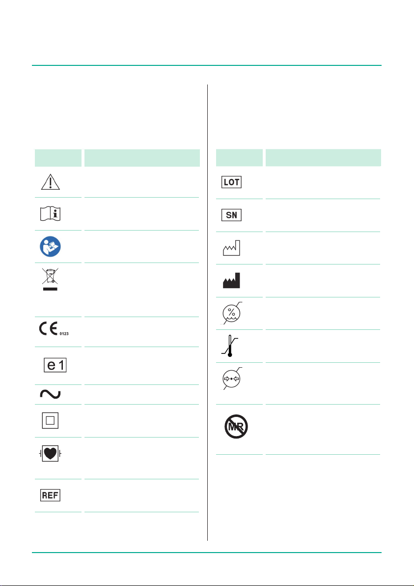
2 Symbols
2.1 Symbols on the product
and packaging
Symbol Meaning
Caution!
Consult instruction for use
Refer to instruction manual
(Follow instruction for use)
Labeling of electric
and electronic devices
according to directive
2012/19/EU (WEEE)
CE marking according to
Directive 93/42/EEC
ECE test mark
Alternating current
Protective insulation;
protection class II device
Symbol Meaning
Batch number
Serial number
Date of manufacture
(year-month-day)
Manufacturer
Humidity limitation
Temperature limit
Atmospheric pressure
limitation
Not MRI safe
Debrillation-proof typeCF
applied part, see section
19.1 Accessories
Catalog number
8
Page 9
Symbols
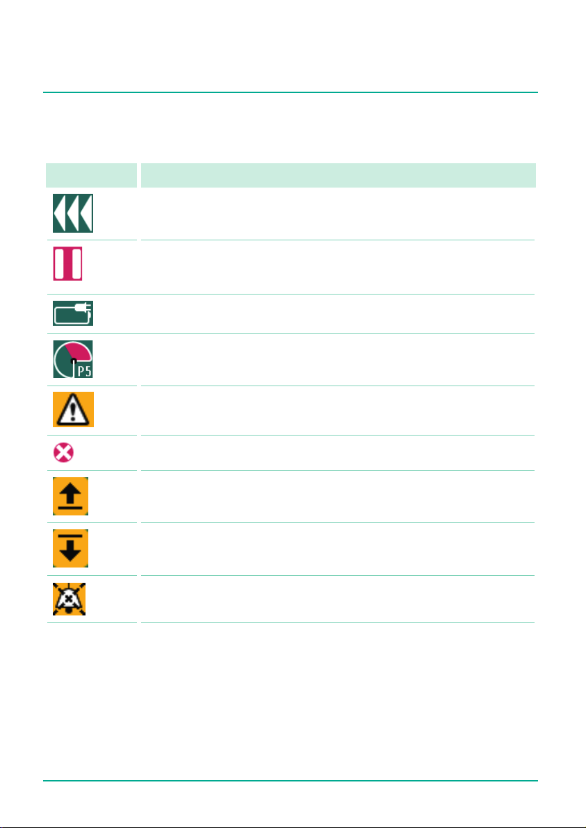
2.2 Symbols on the device‘s display
Symbol Bedeutung
Delivery in progress
Delivery stopped
Mains electricity connection/battery status
Pressure symbol (“manometer”): Indication of P1 to P9 pressure level
set with current system pressure (pointer)
Attention: pre-alarm
Attention: operating alarm
Infusion is above the upper soft limit
Infusion is below the lower soft limit
Pre-alarm temporarily muted
9
Page 10

Intended use
3 Intended use
The Perfusor® compact
pump system
syringe pump used together with authorised syringes and accessories. The pump
is intended for use in adults, children and
newborns for the intermittent or continuous administration of parenteral and enteral
solutions through standard medical access
routes. These access routes include, but are
not limited to, intravenous, intra-arterial,
subcutaneous, epidural and enteral routes.
The system can also be used to administer
drugs indicated for the infusion therapy.
These include, but are not limited to, anaesthetics, sedatives, analgesics, catecholamines etc.; blood or blood components;
solutions for total parenteral or enteral
nutrition and lipids.
is a transportable infusion
plus
infusion syringe
A medical professional should decide on
specic applicability based on the guaranteed characteristics and technical data.
The Perfusor® compact
pump system is intended for use by qualied medical professionals in rooms used
for medical purposes, inoutpatients and
in transport situations. The user must have
received training on the device. The use
of the Perfusor® compact
on the climatic conditions specied in the
technical data. The storage conditions are
detailed in the technical data.
10
plus
infusion syringe
plus
is dependent
Page 11

Safety instructions
4 Safety instructions
Q
Read the safety instructions before
using the device and observe them.
4.1 Safe handling
4.1.1 General
Q
Make sure that the introductory
training on the device is given by
a B. Braun sales representative or
another authorised person.
Q
If the device is dropped or subjected to
external forces: stop using the device
and have it tested by an authorised
service workshop.
Q
Avoid external loads on the syringe
plate sensor.
Q
Protect the device against moisture.
Software
4.1. 2
Q
Consult the instructions for use following each software update to nd
out about the most recent changes to
the device and its accessories.
Q
Ensure that the software version on
the device corresponds to the version
these instructions for use refer to.
Q
Ensure that all devices used in a station have the same software version
installed to avoid mistakes when using
dierently congured devices.
Transport and storage
4.1. 3
Q
Do not hold the device by the drive
head during transport.
Q
Devices stored at temperatures below
the dened operating conditions range
must be kept at room temperature
forat least one hour before being
powered on.
Q
Do not store the pump with the drive
head extended.
Set-up and start-up
4.1.4
Q
For mobile use (patient transport
within the clinic and outside the clinic)
ensure secure mounting or positioning of the device. Changes of position
and strong vibrations can cause minor
changes in the delivery characteristics.
Q
Ensure that the device is properly positioned and secured, and that it is level.
Q
Do not position the device above the
patient.
Q
Before powering on, check the device.
In particular, inspect the syringe
holder and claws for dirt, damage,
missing parts and to ensure that they
function correctly.
Q
Pay attention to audible and visible
alarms and the lighting up of the two
status LEDS during the self-test.
Q
When xing the device to a box rail,
donot x the device near the rail
bracket.
Q
Fully charge the battery before the rst
use without an external power supply.
4.1.5 Stacking
Q
Stack a maximum of three devices on
top of one another.
Q
Do not stack in ambulances or helicopters.
Q
When stacking, ensure that the device
is correctly and safely locked in. You
will hear an audible click sound when
the device is locked in.
11
Page 12

Safety instructions
Control
4.1.6
Q
Stand in front of the device to operate
it. This ensures that you are able to
reach all control elements and that the
display is clearly visible.
Q
Only connect the patient once the
syringe has been positioned correctly
and the syringe plunger plate is being
correctly held by the drive head claws.
Ensure adequate protection against
free-ow when changing syringes
in order to avoid an unwanted dose
administration.
Q
Ensure that the syringe plunger plate
sits ush with the drive head syringe
plate sensor.
Q
Only use approved syringes/catheters
for their intended medical use.
Q
Position the infusion line to the
patient so that it does not have any
kinks.
Q
Ensure that installation in rooms
used for medical purposes is done in
accordance with the regulations (e.g.,
VDE 0100, VDE 0107 and/or IEC specications). Observe all country-specic
regulations and national deviations.
Q
Do not operate the device near inammable anaesthetics.
Q
Always check the plausibility of the
values shown on the display.
Q
Ensure that there is additional patient
supervision (e.g. monitoring) if life
sustaining drugs are administered.
Q
Do not apply any force to the drive
head during delivery as this could
trigger an alarm.
Q
When administering highly-eective
drugs, have a second device ready for
the drug.
Q
Avoid mechanical eects on the
device. Ifthe device is moved while in
operation, the set delivery rate may be
exceeded/not be reached.
Q
Monitor the administration of highlyeective drugs accordingly.
Q
Irrespective of the soft limits, ensure
that the values set for the patients are
the medically correct values.
Q
When using the device near equipment
that can cause higher interference
emissions (e.g. electrosurgical devices,
magnetic resonance imaging units,
mobile telephones) keep the device
the recommended safe distance away
from such equipment.
Alarms and sta call
4.1.7
Q
The volume of the device‘s acoustic
alarms can be adjusted for the environmental conditions. This ensures
that the alarms are clearly audible.
Q
Always monitor the pump alarms.
Theuse of data communication via
an accessory cable or sta call does
not adequately replace monitoring
thealarms.
Q
Check the sta call before each use
ofthe device.
12
Page 13

Safety instructions
4.1.8 Accessories and consumables
Q
Change the disposables according to
your local infection control policy.
Q
Only use pressure-tested disposable
items (min.2bar/1,500mmHg).
Q
Only use the device with accessories
and consumables that have been
approved for use with the device.
Q
Ensure·adequate·protection·against·f
ree-ow before changing disposable
items.
Q
Always use the device with the smallest possible syringe, provided the
therapy permits this.
Q
See the corresponding manufacturer
information for possible incompatibilities between the device and medicinal
products.
Note: The use of untested or incompatible
disposable items can aect the technical
data.
Q
Use only Luer lock feed systems and
syringes as well as compatible device,
accessory, wear part and disposable
item combinations.
Q
Connected electrical components must
comply with IEC/EN specications
(e.g., IEC/EN 60950 for data processing equipment). Anyone who connects
additional devices is considered a
system congurer, and is therefore
responsible for compliance with system standard IEC/DINEN60601-1-1.
Q
If more than one appliance/infusion
line is connected, mutual interference
cannot be ruled out
.
4.1.9 Enteral nutrition
The Perfusor® compact
plus
can be used for
enteral nutrition.
Q
Do not use enteral uids for the intravenous infusion. This would lead to a
risk of severe injury or death for the
patient.
Q
Only use disposable syringes that have
been designed and designated for
enteral nutrition.
4.2 Electrical connection
Q
Do not use the device if the plug has
visible damage.
Q
Do not use an extension cable that has
not been approved for use with device.
Q
Position the power cable so that it
does not present a trip hazard.
4.3 Safety standards
Q
The device meets all safety standards
for medical electrical equipment in
compliance with IEC/DINEN 60601-1
and IEC/DINEN 60601-2-24.
Q
It complies with the EMCthreshold
limits as specied in
IEC/DINEN60601-1-2 and
IEC/DINEN60601-2-24.
13
Page 14
Description of the device
1 2 4 5 63
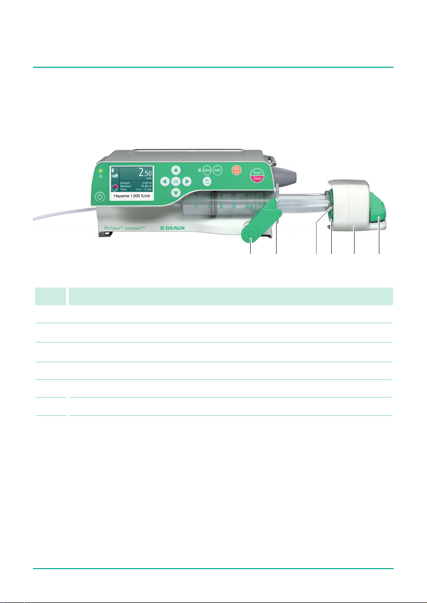
5 Description of the device
5.1 Device overview
No. Name
1 Syringe holder
2 Syringe wings bracket
3 Syringe plate sensor
4 Claws
5 Drive head with emergency lock key
6 Release lever
14
Page 15
Description of the device
1 2 4 53
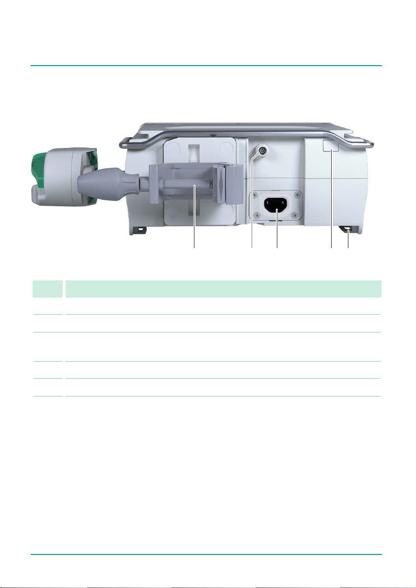
5.2 Interfaces
No. Name
1 Stand clamp
2 Accessory port (e.g. sta call, ambulance)
3 Mains connection (socket for power cable. Inthe event of a power cut, the
device switches to battery mode automatically)
4 Infrared interface (communication in station, service)
5 Guide rails for connecting pumps
15
Page 16
Description of the device
1 2 3 4 5 6 9 107 8
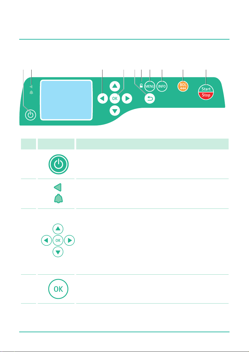
5.3 Display and control elements
No. Element Function
1
On/o key:
Switches the device on and o
2
Status display
Green LED: Delivery
Red LED: Technical alarm, operating alarm
3
Arrow keys:
Q
Scroll through menus
Q
Change settings
Q
Answer yes/no questions
Q
Select scale values and change between digits when
inputting values
Q
Open a function while the infusion is ongoing
or suspended
4
16
OK key:
Q
Select/conrm function
Q
Conrm value/settings/input/alarms
Page 17
Description of the device
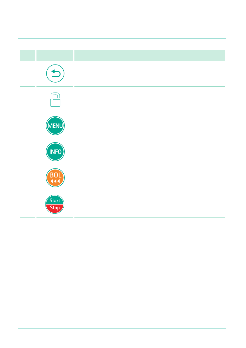
No. Element Function
5
6
7
8
9
10
Back key:
Return to the last display or last menu level
Lock/unlock symbol:
The keypad is locked and unlocked by pressing and holding
down the menu key.
Menu key:
Call up main menu and lock/unlock the device
Info key:
Call up therapy data from the current infusion
Bolus key:
Initiate bolus administration
Start/Stop key:
Start/stop the infusion
17
Page 18
Description of the device
1
2
3
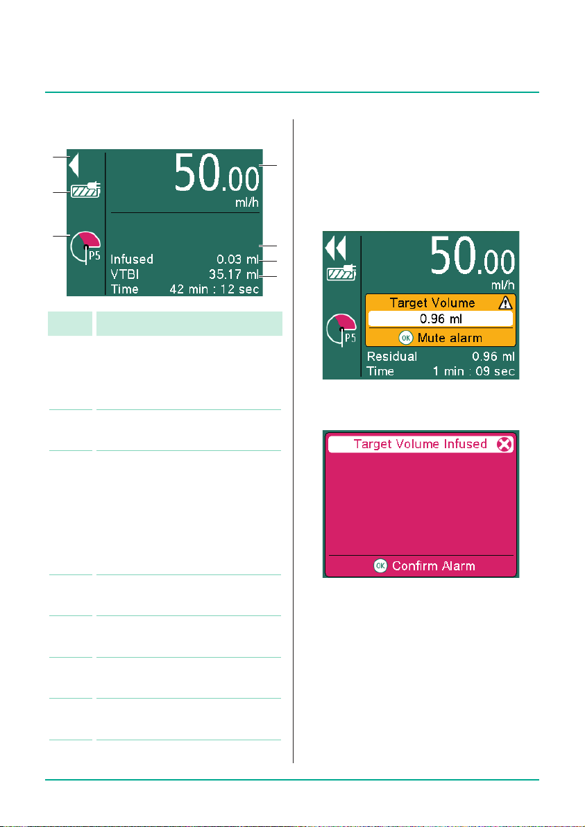
5.4 Display overview
No. Display / Function
1 Moving arrows:
Delivery in progress
(stopped delivery is shown by
two bars)
2 Mains electricity connection/
battery status
3 Pressure symbol (“manometer”):
Indication of P1 to P9 pressure
level set with current system
pressure (pointer)
Note: Pressure detector is
also active when the device is
stopped or in standby mode.
5.5 Alarm status display
Alarms are displayed via a notication on
4
the display, asignal tone and ashing of
thered LED (operating alarm):
Yellow: pre-alarm
5
6
7
Red: operating alarm
4 Set delivery rate with drug
administration unit
5 Volume already administered
Q
Press OK to acknowledge the alarm.
Q
Continue the therapy or start new
therapy.
during the current infusion
6 Remaining volume for the
current infusion
7 Remaining time for the current
18
infusion
Page 19

Menu structure / device functions
6 Menu structure /
device functions
6.1 Main menu
Menu Function
Rate,
volume &
time
Drug Select the drug for the
Dose
calculation
Enter/change infusion
rate or calculate rate by
entering the volume limit
and infusion duration
intended use
Calculate the rate of
administration
6.1.1 Main menu >
Rate, volume & time
The device oers the option of entering the
delivery rate, avolume or a time limit. Ifthe
volume limit and infusion time are entered,
the rate will be calculated automatically.
Main menu > Drug
6.1. 2
Menu Function
Stations Select station
Patient
prole
Categories Select drug categories
Drugs Select drug
Concentrations
Note: All menu items except “Drug” are
optional and are only requested if there are
corresponding entries in the database.
Select patient prole:
Default patient prole
or a previously created
prole
Select concentration
Reset
therapy
Settings... Congure the device
Delete all therapy
settings
Note: the infused volume
(inf. vol.) is not deleted.
settings
19
Page 20

Menu structure / device functions
Main menu > Dose calculation
6.1. 3
Menu Function
Dose unit Select unit:
Q
mg
Q
μg
Q
ng
Q
IU
Q
mEq
Q
mmol
Active
substance
quantity
Volume
Calculate
using:
Set the concentration
by entering the quantity
of active substance and
volume
Weight:
Q
Enter the patient’s
weight
Body surface area:
Q
Enter the patient‘s
weight and height
No patient data
Select
e.g. mg/min or mmol/24 h
dose unit
Enter dose Enter desired dose
6.1.4 Main menu > Settings
Menu Function
Night mode Turning night mode on/o
Brightness Select the brightness:
Q
Level 1 (=lowest level)
- to -
Q
Level 9 (=highest level)
Audio
Volume
Select the volume:
Q
Level 1 (=lowest level)
- to -
Q
Level 9 (=highest level)
Pressure
Alarm
Select pressure level:
Q
Level 1 (=lowest level)
- to -
Q
Level 9 (=highest level)
Service … Congure additional
settings:
Q
Language
Q
Date
Q
Time
Q
Bolus rate
Q
KVO
Q
Night schedule
Q
System info
Q
Infusion history
20
Page 21

Menu structure / device functions
6.1. 5 Settings > Service
After the service code has been entered, the
following service settings can be changed:
Menu Function
Language Select language:
Q
German
Q
English
Date Set date in DD.MM.YYYY
format
Time Set time
Bolus rate Enter default bolus rate
KVO Switch KVO on/o
Night
schedule
System
info
Infusion
history
Set night schedule:
Q
On/o
Q
Activate at...
Q
Deactivate at...
Display system information
Q
Hardware version
Q
Software version
Q
Name of the drug le
Q
Time of next safety
check
Q
Station name
Displays a list of changes
to the infusion settings
21
Page 22

Set-up and powering on
7 Set-up and powering on
7.1 Setting up and
connecting the device
7.1.1 Attach/remove the compact
stand clamp
Note: The compact
to the device.
Q
The compact
only be removed and re-attached by a
service technician.
Operating the device on a stand
7.1. 2
Q
Press the lever on the compact
stand clamp.
Turn the compact
the desired position.
Q
Turn the compact
the lever clicks into place.
Operating the device in the
7.1. 3
compact
Q
Follow the compact
tions for use.
Operating the device on
7.1. 4
a wall rail
Q
Press the lever on the compact
stand clamp.
Turn the compact
the desired position.
Q
Turn the compact
the lever clicks into place.
Q
Make sure that the compact
clamp is not xed at the point where
the wall rail is attached to the wall.
plus
stand clamp is xed
plus
stand clamp should
plus
stand clamp to
plus
static clamp until
plus
station
plus
station instruc-
plus
stand clamp to
plus
static clamp until
plus
plus
plus
stand
plus
7.1. 5 Connecting the device to
the mains electricity
DANGER! Risk of death from electric
shock.
Q
Only connect the device to a mains
power supply with a protective earthing conductor.
Q
Connect the power cable with mains
connection to the device.
Q
Position the power cable so that it
does not present a trip hazard.
Q
Plug the mains plug into the socket.
Operating the device with
7.1. 6
a battery
Q
Ensure that the battery in the device is
suciently charged.
7.2 Powering on the device on
for the rst time
Q
Device switched on
Q
Select and insert the syringe,
see section 8.2.
Q
Congure additional device settings,
see section 7.3.
7.3 Congure device options
Q
Device switched on
Q
No patient connected
Q
No ongoing infusion
Q
Press the Menu key.
The main menu is displayed.
Q
Select Settings... and press OK
to conrm.
The “Settings” screen is displayed.
22
Page 23

Set-up and powering on
7.3.4 Conguring the
pressure alarm limit
WARNING! Danger to the patient
from an incorrectly set pressure
alarm limit.
Q
Ensure that an appropriate pressure
level is selected in order to minimize time to alarm.
7.3.1 Turning night mode on/o
In night mode the display brightness is
reduced.
Q
Select Night mode and press OK
toconrm.
Q
Select On/O and press OK
to conrm.
Setting display brightness
7.3.2
Q
Select Brightness and press OK
toconrm.
Q
Select brightness level and press OK
toconrm.
–
Level 1 (=lowest level)
- to -
–
Level 9 (=highest level)
Setting the Audio Volume
7.3.3
Q
Select Audio Volume and press OK
to conrm.
Q
Select Audio Volume level and press
OK toconrm.
–
Level 1 (=lowest level)
- to -
–
Level 9 (=highest level)
It may be necessary to change the pressure
alarm limit due to various inuencing factors, e.g. syringe friction, extension line
length and inner diameter, uid viscosity
and the lter used in the system set-up.
Note: The set pressure level aects the time
to alarm. In order to minimize the time to
alarm, it is recommended that you start
with a low pressure level and to increase if
required.
Note: In the event of a pressure alarm, the
post occlusion bolus will be automatically
reduced.
Q
Select Pressure alarm and press OK
toconrm.
Q
Select alarm level and press OK
toconrm.
–
Level 1 (=lowest level)
- to -
–
Level 9 (=highest level)
23
Page 24

Set-up and powering on
Alarm level Pressure value
1 0.100 bar (75 mmHg)
2 0.237 bar (178 mmHg)
3 0.375 bar (281 mmHg)
4 0.512 bar (384 mmHg)
5 0.649 bar (487 mmHg)
6 0.787 bar (590 mmHg)
7 0.925 bar (694 mmHg)
8 1.063 bar (797 mmHg)
9 1.200 bar (900 mmHg)
The set pressure level is shown with aP
(forpressure) and a number. Inaddition,
ared area shows how quickly the set
pressure alarm limit will be reached. The
“manometer” display shows the current
pressure in the system. The lower the set
pressure alarm limit level is, the larger the
red area is, the quicker this limit is reached
and a pressure alarm triggered.
7.3. 5 Conguring service settings
Q
Select Service... and press OK
to conrm.
Q
Enter the service code and press OK
to conrm.
The “Service Menu” screen is displayed.
Conguring the display language
Q
Select Language and press OK
to conrm.
Q
Select the language and press OK
to conrm.
Setting the date and time
Q
Select Date and press OK to conrm.
Q
Enter the day, month and year and
press OK to conrm.
Q
Select Time and press OK to conrm.
Q
Enter the time and press OK
to conrm.
Setting the bolus rate
Q
Select Bolus rate and press OK
to conrm.
Q
Set the bolus rate and press OK
to conrm.
24
Page 25

Set-up and powering on
Switching KVO on/o
The pump can continue to deliver after a
preselected volume or a preselected time
with a pre-dened KVO rate (see section16)
has been reached. The duration of the KVO
delivery is established in the service program.
Q
Select KVO and press OK to conrm.
Q
Select On/O and press OK
to conrm.
Setting the night schedule
Q
Select Night schedule and press OK
to conrm.
Q
Select On/O and press OK
to conrm.
Q
Select On/O and press OK
to conrm.
Q
Select Activate and press OK
to conrm.
Q
Enter the time and press OK
to conrm.
Q
Select Deactivate and press OK
to conrm.
Q
Enter the time and press OK
to conrm.
7.4 Locking/unlocking
the keypad
Locking the keypad protects the device
against accidental use.
Q
Ongoing infusion
Q
Press the menu key and hold for a
fewseconds to lock the keypad.
Q
The process for unlocking the keypad
is the same.
Note: The keypad lock is not activated for
all keys. Itis always possible to stop the
infusion using the Start/Stop and On/O
keys.
25
Page 26

Operation
8 Operation
Q
Device settings congured
8.1 Switching on the device
Q
Device connected to the mains electricity or battery fully charged.
Q
Press the On/O key on the device.
The device will perform a self-test:
Note: Pay attention to audible and visible
alarms, the lighting up of the two status
LEDs and the display during the self-test.
8.2 Inserting the syringe
Q
Device switched on.
Q
Press the release lever and slide the
drive head to the right.
Q
Pull the syringe holder and turn it to
the left.
Q
Insert the syringe. Ensure that the
syringe wings have been correctly
inserted into the bracket.
Q
Pull the syringe holder and turn it to
its original position.
Q
Press the release lever and slowly slide
the drive head towards the syringe.
When the drive head reaches the
syringe plunger plate, the syringe is
automatically grasped.
The “Select syringe” message is displayed.
Q
Select syringe type and press OK
to conrm. Make sure that the syringe
type displayed is the same as the
inserted syringe.
Note: “Support for bolus-free insertion”
does not release the user from their duty of
care when changing the syringe.
Note: Always use the device with the small-
est possible syringe, provided the therapy
permits this.
Please see the notes in section 15.2
Typicalstart-up and trumpet curves.
8.3 Setting the infusion values
Q
Syringe inserted and selected
Note: Depending on the last therapy, the
pump can be set by using the delivery rate
or by using drug library.
8.3.1
Entering the delivery rate
Q
Enter the delivery rate using the arrow
keys.
Q
Start the infusion with the Start/Stop
key.
- or -
Q
Press OK to conrm the rate.
The Overview screen is displayed.
Q
Select Vol./Time and press OK
to conrm.
Q
Enter the volume or time limit and
press OK to conrm.
26
Page 27

Operation
Any values still missing are automatically calculated and displayed.
Note: In addition to the volume and time
limit, the infusion rate can also be adjusted
in the Overview screen.
Q
Start the infusion with the Start/Stop
key.
8.4 Starting and stopping
the infusion
Q
Values for the treatment set
Q
Press the Start/Stop key to start the
infusion.
The moving arrows in the display and
the green LEDs show that the delivery
is taking place.
8.5 Activating standby
In the event of longer interruptions, the
user has the option of retaining the set values and continuing the infusion at a later
time.
Activating standby mode
Q
Syringe inserted and selected
Q
Press and hold the On/O key until
the pump display says it is in standby
mode.
Adjusting device standby time
Q
Press the left arrow key.
Q
Enter the desired time and press OK
to conrm.
Note: The infusion rate set can be changed
during an ongoing infusion by pressing the
OK key.
Q
Interrupt or stop the infusion by pressing the Start/Stop key to start a new
therapy.
Note: After stopping the therapy, “Reset
therapy” must be selected in the menu
before a new therapy can be started.
Ending standby mode
Q
Press the On/O key or Back key.
Q
Press the Start/Stop key.
The delivery is re-started with the
previously set values.
27
Page 28

Operation
8.6 Administering bolus
There are three dierent options for bolus
administration:
Q
Manual bolus
Q
Bolus with preselection of the bolus
volume
Q
Bolus with preselection of the bolus
volume and the bolus duration
Note: If the bolus administration is not
started after the Bolus key is pressed,
thedevice automatically returns to the
delivery screen for the ongoing infusion.
Note: The pressure threshold is automati-
cally increased during bolus administration.
8.6.1
Administering a manual bolus
Q
Press the Bolus key.
The “Bolus” screen is displayed.
Q
Press the Bolus key again and hold it.
Fluid is delivered as long as the key is
pressed or until the maximum duration/
dose have been reached. The delivered
bolus volume is displayed.
Q
Release the Bolus key.
The bolus administration is ended and
the infusion continued.
Note: Manual bolus administration is lim-
ited to a max. 10s or 10% of the syringe
content. The bolus administration is automatically stopped, but it can be continued
by pressing the Bolus key again.
8.6.2
Administering a bolus with preselected bolus volume/bolus duration
WARNING! Danger to the patient
from an overdose. At a bolus rate of
1,200 ml/h, 1 ml is reached after 3 s.
Q
Press the OK key to stop the bolus
administration.
Q
Press the Bolus key to access the bolus
menu.
Entering the bolus volume
Q
Press the left arrow key and enter the
desired bolus volume.
Q
Press the Bolus key to start the bolus
administration.
Entering the bolus duration (optional)
Q
Press OK to conrm the entry of the
bolus volume.
Q
Select Bolus duration and press OK
to conrm.
Q
Entering the desired bolus duration.
The bolus rate is calculated.
Q
Press the Bolus key.
The bolus administration is started.
After the time has elapsed, the bolus
administration is ended and the infusion continued.
28
Page 29

Operation
8.7 Using the drug database
DANGER! Danger to the patient from
incorrectly selected drug.
Q
Ensure that the correct drug has
been selected.
Up to 3,000 freely selectable drug names,
including corresponding therapy data and
information and up to 10concentrations
per drug in 30categories, can be stored.
The data are loaded using a separate PC
programme.
The drug database can be used to select
adrug name with saved therapy data.
The procedure for selecting a drug is
described below:
Q
Pump has just been switched on or
“Reset therapy” has been selected.
Q
Press the Menu key.
The main menu is displayed.
Q
Select Drug and press OK to conrm.
Q
If there is more than one prole available:
–
Select station and press OK
to conrm.
–
Select patient prole and press OK
to conrm.
Q
Select drug category and press OK
to conrm.
Q
Select drug and press OK to conrm.
Q
If avail able, read the information in
the “Drug info” screen and press OK
to conrm.
Q
If necessary, select concentration and
press OK to conrm.
Q
Read the information in the “Drug”
screen and press OK to conrm.
Q
Enter the delivery rate.
Q
Start the infusion with the Start/Stop
key.
- or -
Q
Conrm the delivery rate by pressing
OK.
The “Overview” screen is displayed.
Q
Select Vol./Time and press OK
to conrm.
Q
Enter the volume or time limit and
press OK to conrm.
Any values still missing are automatically calculated and displayed.
Note: In addition to the volume and time
limit, the infusion rate can also be adjusted
in the Overview screen.
Q
Start the infusion with the Start/Stop
key.
8.7.1 Hard and soft limits
Hard limits
Hard limits are xed thresholds for the rate/
dose/bolus volume and bolus rate stored in
the database. Only values within the hard
limits can be entered.
If an attempt is made to exceed
or go below
a hard limit, the following message appears
on the display
:
29
Page 30

Operation
Soft limits
Soft limits for rate/dose/bolus volume and
bolus rate can also be stored in the database. These can be exceeded but the following message appears on the display.
The following symbols that describe the
status of the pump with regard to the soft
limits are described:
Symbol Meaning
No
symbol
Infusion is within the soft
limits
Infusion is above the upper
soft limits
8.8 Calculating the dose
The Dose calculation function is used to
calculate the delivery rate inml/h based on
the dose parameters entered.
Q
Syringe inserted and selected
Q
Press the Menu key.
The main menu is displayed.
Q
Select Dose calculation and press OK
to conrm.
Q
Select active substance unit and press
OK to conrm.
Q
Enter active substance quantity and
press OK to conrm.
Q
Enter volume and press OK to conrm.
The “Calculate Using” screen is displayed.
30
Infusion is below the lower
soft limits
Calculating without patient data
The delivery rate is calculated without any
patient data being entered.
Q
Select No patient data and press OK
to conrm.
Q
Select dose unit and press OK
to conrm.
Q
Enter dose.
Note: Pressing the OK key brings up the
Overview screen.
Page 31

Operation
Q
Check the plausibility of the displayed
values.
Q
Start the infusion with the Start/Stop
key.
Calculate using: Weight
Q
Select Weight and press OK to conrm.
Q
Enter weight and press OK to conrm.
Q
Select dose unit and press OK
to conrm.
Q
Enter dose.
The rate is automatically calculated.
Note: Pressing the OK key brings up the
Overview screen.
Q
Check the plausibility of the displayed
values.
Q
If necessary, enter the volume or time.
Q
Start the infusion with the Start/Stop
key.
Calculate using: Body surface area
Q
Select Body surface and press OK
to conrm.
Q
Enter weight and press OK to conrm.
Q
Enter the patient’s height and then
press OK to conrm.
Q
Select dose unit and press OK
to conrm.
Q
Enter dose.
The rate is automatically calculated.
Note: Pressing the OK key brings up the
Overview screen.
Q
Check the plausibility of the displayed
values.
Q
Start the infusion with the Start/Stop
key.
8.9 Entering a combination
of delivery rate, volume
and time
Q
Syringe inserted and selected
Q
Press the Menu key.
The main menu is displayed.
Q
Select Rate, volume & time and press
OK to conrm.
Q
Enter two of the following parameters
and press OK to conrm:
–
Rate
–
Volume
–
Time
The third parameter is automatically
calculated.
If one or more parameters are entered,
changing a parameter has the following
eects on the other parameters.
Q
Rate (or dose rate) changed:
–
If only the volume has been
entered, the remaining time is
adjusted.
–
If only the time has been entered,
the remaining volume is adjusted.
–
If the volume and time have been
entered, the remaining time is
adjusted.
31
Page 32

Operation
Q
Volume changed:
–
If only the rate has been entered,
the remaining time is adjusted.
–
If only the time has been entered,
the rate (or dose rate) is adjusted.
–
If the rate and time have been
entered, the remaining time is
adjusted.
Q
Time changed:
–
If only the rate has been entered,
the remaining volume is adjusted.
–
If only the volume has been
entered, the rate (or dose rate) is
adjusted.
–
If the rate and volume have been
entered, the remaining volume is
adjusted.
8.10 Resetting the therapy
The “Reset therapy” function is used to
delete all currently set therapy data. Anew
therapy can be started.
Note: Reset therapy can only be selected if
the therapy has been stopped.
Q
Press the menu key and select
Reset therapy and press OK
to conrm.
Q
Press the up arrow key to reset the
therapy.
8.11 Changing the syringe
Do not remove the syringe if the drive
head claws are closed.
CAUTION! Damage to the syringe/
drive head claws.
Q
Press the Start/Stop key to stop the
infusion.
The green LED turns o.
Q
Ensure adequate protection against
free-ow.
Q
Press the release lever and slide the
drive head to the right.
Q
Pull the syringe holder and turn it to
the left. Hold the syringe while doing
so.
Q
Remove the syringe.
Q
Insert the new syringe, see section 8.2.
Q
Start the infusion, see section 8.4.
8.12 Ending the infusion
Do not remove the syringe if the drive
head claws are closed.
CAUTION! Damage to the syringe/
drive head claws.
Q
Press the Start/Stop key to end the
infusion.
The green LED turns o.
Q
Ensure adequate protection against
free-ow.
Q
Press the release lever and slide the
drive head to the right.
Q
Pull the syringe holder and turn it to
the left. Hold the syringe while doing
so.
Q
Remove the syringe.
32
Page 33

Operation
Note: When removing a syringe if the
syringe plunger plate is not released by the
claws, the emergency release button should
be pressed. The emergency release button
is on the outside of the drive head. Itcan
be pressed using a pointed object (e.g.
ballpoint pen). Once it has been pressed
the claws can be opened by hand and the
syringe removed. Send the device to technical service.
Q
Return the syringe holder to original
position
Q
Slide the drive head towards the pump
into parking position.
8.13 Switching o the device
Q
Infusion ended
Note: The device cannot be switched o if
a disposable item is inserted. Instead it will
go into standby mode.
Ensure the drive head is in the parking position.
Q
Press the On/O key for approx.
1.5seconds.
The device switches o.
8.14 Priming the infusion line
Note: This function is not avail able in the
pump factory default. The function can
be activated by a service technician on
request.
Q
Connection to the patient removed
Q
Infusion stopped
Q
Press the Bolus key.
The “Prime infusion line” screen is
displayed.
Q
Press the up arrow key to prime the
line.
A message asking if the line is disconnected from the patient is displayed.
Q
Press the up arrow key to start the
priming.
The disposable item is primed with the
maximum delivery rate.
Note: After successful priming, the line can
be primed again using the up arrow key.
Q
Press the down arrow key to end the
priming.
33
Page 34

Alarms
9 Alarms
9.1 Device alarms
If a device alarm is triggered the infusion is
stopped immediately.
Q
Press the On/O key to switch o the
device.
Q
Switch the device on again.
If there is another technical alarm:
Q
Disconnect the patient.
Q
Remove the disposable article.
Q
Switch o the device and send it to
the technical service.
9.2 Pre-alarms and operating
alarms
WARNING! Danger to the patient
from an incorrectly set alarm limits.
Q
Ensure that the alarm limits are set
so that the alarm can be triggered
in good time. This applies for maximum pressure in particular.
9.2.1 Pre-alarms
In the event of a pre-alarm, anacoustic
signal sounds and a sta call is activated.
The display remains in pre-alarm until the
operating alarm goes o. Pre-alarms do not
cause delivery to be interrupted.
Display
Meaning
message
Q
“Volumes
nearly infused”
Preselected volume
has almost been
infused
Q
Remaining volume
is displayed
“Disposable
syringe nearly
empty”
“Infusion
time nearly
Small infusion volume
remaining in the
syringe
Preselected time is
almost over
reached”
“Battery
nearly empty”
The battery is almost
discharged
The operating alarm has a high priority.
Pre-alarms and reminder alarms have a
lower priority. Ifthere are two pre-alarms
at the same time, the pre-alarm with the
shorter remaining time is displayed.
The time lag between the triggering of the
alarm and the activation of a sta call is less
than a second and is therefore negligible.
If the power supply to the device is cut for
less than 30 seconds, the alarm information
is still retrievable because it is stored by
capacitors in the device.
34
A pre-alarm can be muted for 2 minutes by
pressing the OK key. The following symbol is
shown in the display:
Page 35

Alarms
9.2.2 Operating alarms
In the event of an operating alarm, the infusion is stopped. Anacoustic signal sounds,
thered LED ashes and a sta call is activated.
Display message Meaning
“Target volume
Preselected volume has been infused
reached”
“Disposable
No infusion solution is left in the syringe.
syringe is empty”
“Time reached” Preselected time haselapsed
“Battery empty” The battery is discharged
Q
Connect device to mains and/or have battery replaced by a
service technician
The battery alarm will sound for 3 min. Then the pump will
automatically turn o
“Pressure
too high”
There is an occlusion in the system. The set level was exceeded
Q
The pump automatically implements a bolus reduction
“KVO nished” KVO time has elapsed
“Syringe holder
open”
“Syringe not
correctly
Syringe bracket was opened during the ongoing infusion
Q
Close syringe bracket
The wings of the syringe are not correctly inserted
Q
Insert syringe correctly, see section 8.2
inserted”
“Calibrate device” Pump calibration data has changed (e.g.after an update)
Q
Recalibrate device using the service programme
“No battery
in the device”
It is not possible to use the pump without a battery
Q
Ask a service technician to insert a battery
35
Page 36

Alarms
9.3 Reminder alarm
Reminder alarms are triggered in the following cases:
Q
A syringe is inserted, the pump is not
delivering and the device is not operating for two minutes.
Q
A value input was started but not
completed and conrmed.
Q
After the standby time has elapsed
A sta call is activated and the following
screen is displayed:
36
Page 37

Cleaning and care
10 Cleaning and care
Q
Device is switched o
Q
Device is unplugged from the mains
Q
Device accessories are disconnected
10.1 Cleaning
Q
No pointed objects should be used for
cleaning.
Q
Do not put excess stress on the claws
when cleaning.
Q
Clean the surface of the device with
mild soap solution.
Q
Do not spray disinfectant into the
openings in the housing.
Q
Do not use disinfectant spray on electrical connections. Recommendation:
Use disinfectants manufactured by
B. Braun (e.g., Meliseptol, Melsitt10%
and Melsept SF10%) for wipe disinfection.
Q
Allow the device to air dry for at least
1min before operation. Donot spray
into device openings (e.g., cooling
vents, mains power plugs, interfaces).
Q
Observe all hygiene regulations.
Q
Clean accessories according to the
instructions.
Note: Substances from the groups of disin-
fectants listed below are approved, for normal
cleaning according to the manufacturer’s
instructions:
Alcohols Peroxides
QAC Active chlorine
Aldehydes Acids
Alkylamines Phenoles
10.2 Battery operation and
maintenance
The device is equipped with a modern lithium-ion battery that, atthe time of delivery,
guarantees an operating time of 8hours at
5ml/h. For optimal treatment of the battery, the device is equipped with protection
against overcharge and deep depletion.
The battery is charged by the device during
mains operation. Inthe event of a power
cut or disconnection from the mains, the
pump automatically switches to battery
mode.
The battery status indicator in the display
isa trend display (low, medium, high).
Note for optimal battery
10.2.1
operation
Battery life may vary due to
Q
Ambient temperature
Q
Varying loads
Therefore, please observe the following:
Q
Under normal temperature conditions,
abattery can be fully discharged and
recharged around 300 times before its
capacity decreases to around half of
the original nominal value.
Q
When the device is in mains operation, the battery discharges slowly and
may be fully exhausted after a month
even if the device is not in operation.
Inthis case the battery does not reach
its original capacity after one charge;
ittakes several charging and discharging cycles for the battery to achieve
its original capacity.
37
Page 38

Decommissioning
Q
Optimal battery life will then only be
achieved if the pump is in continuous operation at room temperature
in charged state. The battery display
on the pump is an approximate value
based on the current delivery rate.
Ifthe battery is old, the “battery
display” may dier from the actual
achievable operating time.
CAUTION! Risk of injury from the
battery exploding or leaking.
Q
Do not open or burn the battery.
11 Decommissioning
Q
No ongoing therapy
Q
No patient connected
Q
Remove accessory parts and dispose
of according to the instructions.
Q
Switch o the device and disconnect
from the mains.
Q
Prepare the device for storage or disposal.
–
Comply with the storage conditions.
–
Follow the notes on disposal.
10.2.2
Changing the battery
Q
The battery should only be changed by
a service technician.
12 Maintenance and repair
WARNING! Risk of injury and/or
malfunction from incorrect repair.
The device does not contain any parts
that the user can repair themselves.
Q
Do not repair defective devices
independently.
Q
Send defective devices to the
B. Braun service.
WARNING! Risk of injury and/or mal-
function from device modications.
Q
Do not modify the device.
Note: Modications and/or incorrect repair
of medical devices can lead to a loss of
guarantee/warranty claims and any authorisations.
Q
Replace damaged accessories with
original accessories.
38
Page 39

Disposal
13 Disposal
The device should be returned to B. Braun
for further disposal.
Q
Observe all country-specic regulations when disposing of equipment
locally.
Q
Do not dispose of electrical devices
and batteries in domestic waste.
14 Safety check/service
A safety check must be performed on the
device every two years in accordance with
the checklist, with results entered into the
medical device log. The service may only be
performed by personnel who have received
training from B. Braun.
15 Start-up and
trumpet curves
15.1 Signicance in
clinical practice
Trumpet curves show the recorded maximum and minimum deviations in ow rate
compared to the delivery rate per time
interval.
In clinical practice, the trumpet curve
makes it easier for the treating doctor to
decide if the pump is suciently precise for
the administration of the desired drug.
Q
Reconcile drugs with short half lives,
inparticular, with the delivery accuracy in this period on the trumpet
curve.
The physiological eect of the drug can
be aected by the ow and the disposable
article.
Q
Ensure that the prescription is in line
with the start-up/trumpet curve and
the set ow rate.
39
Page 40

Start-up and trumpet curves
-10
-5
0
5
10
50 ml Omnifix
Förderrate = 1 ml/h
15
-15
Epmax
Epmin
0,5
1,5
2,0
2 5 11 19
Beobachtungsfenster p x ∆t [min]
31
Zeit [hh:mm]
Prozentualer Flussfehler
-10
-5
0
5
10
50 ml Omnifix
Förderrate = 5 ml/h
15
-15
2 5 11 19
Beobachtungsfenster p x ∆t [min]
31
Prozentualer Flussfehler
Epmax
Epmin
Anlaufkurven Trompetenkurven
0,5
1,5
2,0
-10
-5
0
2 5 11 19
Beobachtungsfenster p x ∆t [min]
Prozentualer Flussfehler
31
5
10
-10
-5
0
2 5 11 19
Beobachtungsfenster p x ∆t [min]
Prozentualer Flussfehler
31
5
10
Epmax
Epmin
Epmax
Epmin
Zeit [hh:mm]
Anlaufkurven Trompetenkurven
20 ml Omnifix
Förderrate = 1 ml/h
20 ml Omnifix
Förderrate = 5 ml/h
-10
-5
0
2 5 11 19
Beobachtungsfenster p x ∆t [min]
Prozentualer Flussfehler
31
5
10
Epmax
Epmin
5 ml Omnifix
Förderrate = 1 ml/h
0,5
1,5
2,0
15.2 Typical start-up and
trumpet curves
Start-up curves
Flow Q(t) [ml/h]
Fluss Q(t) [ml/h]
5 ml Omnifix
Förderrate = 1 ml/h
Delivery rate = 1 ml/h
Fluss Q(t) [ml/h]
Flow Q(t) [ml/h]
Delivery rate = 1 ml/h
1
0
Flow Q(t) [ml/h]
Fluss Q(t) [ml/h]
1
0
Flow Q(t) [ml/h]
Fluss Q(t) [ml/h]
0
40
0:30 1:00 1:30 2:00
Zeit [hh:mm]
Time [hh:mm]
20 ml Omnifix
Delivery rate = 1 ml/h
Förderrate = 1 ml/h
0:30 1:00 1:30 2:00
Zeit [hh:mm]
Time [hh:mm]
20 ml Omnifix
Förderrate = 5 ml/h
Delivery rate = 5 ml/h
0:30 1:00 1:30 2:00
Time [hh:mm]
1
0
Flow Q(t) [ml/h]
Fluss Q(t) [ml/h]
0
0:30 1:00 1:30 2:00
Zeit [hh:mm]
Time [hh:mm]
Delivery rate = 5 ml/h
0:30 1:00 1:30 2:00
Time [hh:mm]
Page 41

Start-up and trumpet curves
31
∆
31
Beobachtungsfenster p x ∆t [min]
Trumpet curves
Percentage flow error
Prozentualer Flussfehler
10
5
0
-5
-10
2 5 11 19
Percentage flow error
Prozentualer Flussfehler
10
5
0
-5
-10
2 5 11 19
Prozentualer Flussfehler
Percentage flow error
10
5
0
-5
-10
2 5 11 19
5 ml Omnifix
Delivery rate = 1 ml/h
Förderrate = 1 ml/h
Epmax
Epmin
Observation window p x Δt [min]
Beobachtungsfenster p x ∆t [min]
20 ml Omnifix
Delivery rate = 1 ml/h
Förderrate = 1 ml/h
Epmax
Epmin
Observation window p x Δt [min]
Beobachtungsfenster p x ∆t [min]
20 ml Omnifix
Förderrate = 5 ml/h
Delivery rate = 5 ml/h
Epmax
Epmin
Observation window p x Δt [min]
31
31
31
Prozentualer Flussfehler
Percentage flow error
15
10
5
0
-5
-10
-15
2 5 11 19
Percentage flow error
Prozentualer Flussfehler
15
10
5
0
-5
-10
-15
2 5 11 19
Note: Every syringe has certain tolerances
in start-up behaviour (depending on the
syringe manufacturer, syringe plunger
material, siliconisation of the cylinder etc.).
In order to keep the delay as short as
possible, the syringe should be as small
as possible and the plunger moved before
the syringe is inserted in order to work
through the rubber stopper’s breakloose
force behaviour.
The device is equipped with start acceleration, which enables a quick infusion start
after each syringe change.
50 ml Omnifix
Förderrate = 1 ml/h
Delivery rate = 1 ml/h
Epmax
Epmin
Observation window p x Δt [min]
Beobachtungsfenster p x ∆t [min]
50 ml Omnifix
Förderrate = 5 ml/h
Delivery rate = 5 ml/h
Epmax
Epmin
Observation window p x Δt [min]
Beobachtungsfenster p x
t [min]
Note: Always use the device with the
smallest possible syringe, provided the
therapy permits this.
41
Page 42

Start-up and trumpet curves
This is particularly important if highly
concentrated or life-sustaining drugs with
short half-lives are to be infused at low
infusion rates.
When infusing at low rates and with large
syringes, there can be deviations from
the pump‘s technical data, which can
lead to delivery deviations, delayed startup behaviour and longer alarm times in
the event of system occlusions (pressure
alarms).
Recommendation
Syringe size [ml]
Recommended
50/60
30 20
1 1 0.5
minimum rate [ml/h]
Recommendation
Syringe size [ml] 10 5 3
Recommended
0.1
0.05
0.01
minimum rate [ml/h]
Note: The system accuracy is normally
±2% of the volume, measured using the
trumpet curve test method according
to IEC60601-2-24 at a rate of 1ml/h
(at20°C ± 2°C) and using the recommended syringes.
Start-up curves
Measurement interval
Δt = 0.5min
Measurement duration T = 120 min
Flow Q
i
(ml/h)
Trumpet curves
(Measured values for second hour
in each case)
Measurement interval
Observation interval
Δt = 0.5min
p x Δt [min]
These graphs show the accuracy and
uniformity of ow over time. Take into
account:
Q
The delivery behaviour and the
delivery accuracy are fundamentally
aected by the type of syringe used
(disposable item).
Q
Deviations from the pump technical
data cannot be ruled out for competitors’ syringes.
42
Page 43

Start-up and trumpet curves
Zeit (h:mm:ss)
P5 P9P1
1:26:24
1:12:00
0:57:26
0:43:12
0:28:48
0:14:24
0:00:00
Druckstufe
15.3 Alarm times
The following graphs show the alarm times
15.3.1 Omnix® 50 ml
Time [hh:mm:ss]
Omnifix® 50 ml
of the B. Braun syringe shown according to
pressure and syringe type.
Note: The alarm times for syringes from
other manufacturers may vary slightly.
Note: At a rate of 0.01 ml/h the alarm time
is > 4 h.
Manufactured by Syringe type Article number
B. Braun OPS 50ml KK 8728810F-06 01:07 15:20
B. Braun OMNIFIX 50 KK 4617509F 01:31 14:24
B. Braun OMNIFIX 30 4617304F 00:52 09:28
B. Braun OPS 20ml 8728615 01:16 06:12
B. Braun OMNIFIX 20 4617207V 00:40 06:28
B. Braun OMNIFIX 10 4617100V 01:02 05:04
B. Braun OMNIFIX 5ml 4617053V 00:26 02:35
B. Braun OMNIFIX 3ml 4617022V 00:11 01:57
B. Braun OMNIFIX 2ml 4617029V 00:31 02:13
Terumo Terumo 50ml SS+50L1 03:07 22:43
Terumo Terumo 30ml SS*30LE1 02:24 13:58
Terumo Terumo 10ml SS*10LE1 01:20 05:30
Terumo Terumo 5ml SS*05LE1 01:08 03:45
Becton Dickinson Plastipak 50ml 300865/300869 04:48 19:20
Becton Dickinson Plastipak 30ml 301229 03:06 10:17
Becton Dickinson Plastipak 20ml 300629 02:44 10:34
Becton Dickinson Plastipak 10ml 305959 01:49 05:10
Becton Dickinson Plastipak 5ml 309649 00:16 02:22
Becton Dickinson Plastipak 3ml 309658 00:44 02:35
Fresenius Kabi AG Injectomat 50ml 9000701 06:21 23:42
Stanislaw Margol Margomed 50ml 007111, 007121 01:44 22:56
Becton Dickinson Precise 50ml A/P 300144 04:13 18:58
Becton Dickinson Precise 20ml A/P 300141 01:36 06:12
Becton Dickinson LuerLok 10ml A/P 302149 01:28 04:54
Becton Dickinson LuerLok 5ml A/P 302135 01:02 04:05
Becton Dickinson LuerLok 3ml A/P 302113 00:23 02:27
Pressure level = 1
0.1 bar
max. alarm times
[mm:ss]
1 ml/h
5 ml/h
Pressure level
Pressure level = 9
1.2 bar
max. alarm times
[mm:ss]
43
Page 44

Technical data
16 Technical data
Note: The delivery accuracy, pressure alarm and alarm reaction times apply at room tem-
perature and with water as the test material. Dierent media viscosities and temperatures
may lead to deviations.
Parameter Value
Type of device Infusion syringe pump
Product classication According to Directive 93/42 EEC:
Q
IIb
According to EN 60601-1:
Q
Protection class II
Q
For TypeCF applied parts with debrillation protection
Moisture protection IP34
Q
Power supply
100-240 V, 50-60 Hz, connection via power cable or
compact
Q
12 V DC 12V CP interface cable
Q
10 VA typ.
plus
station
Internal battery
Q
Battery life
Q
Recharging time
Lithium-ion battery
Q
Approx. 8h at 5ml/h with 50ml syringe
Q
Approx. 4h
Power consumption <20 W
Q
Current consumption/
charging current
Max. 0.6Ae (typ. <0.1Ae) at
100-240V, 50-60 Hz
Q
Max. 1.5A (typ. <0.5 A) at 12VDC
Sta call Max. 24V / 0.5 A / 24 VA
(VDE 0834)
EMC IEC/EN 60601-1-2 / 60601-2-24
Time of operation 100% (continuous operation)
Acoustic alarm signal
sound pressure range
44
Nine avail able levels:
45dB(A) to 75dB(A)
Page 45

Technical data
Parameter Value
Q
Interfaces
Operating conditions
Q
Temperature
Q
Relative humidity
Q
Atmospheric pressure
Storage conditions
Q
Temperature
Q
Relative humidity
Q
Atmospheric pressure
Weight Approx. 2.3kg
Cold connector for mains voltage
Q
Accessory port for interface cable 12V CP and sta call
Q
IrDA infrared for communication in the station and for
service
Q
+5 °C … +40°C (+41 °F … +104°F)
Q
30% … 90% (without condensation)
Q
0.54 … 1.06bar
Q
-20 °C … +55°C (-4 °F … +131°F)
Q
20% … 90% (without condensation)
Q
0.5 … 1.06bar
Dimensions in mm
(W x H x D)
Approx. 290 mm x 98 mm x 220 mm
(including compact
plus
stand clamp)
Safety check Every 2 years
Volume preselection 0.1ml - 9,999ml in increments of 0.01ml
Time preselection 00:01 h - 99:59 h
Delivery accuracy ±2% according to IEC/EN 60601-2-24
Occlusion alarm pressure 9 levels from 1.2 bar ± 0.2 bar.
Post occlusion bolus will be automatically reduced.
Alarm in the case of
incorrect dose
Max. bolus volume after
In the event of an incorrect dose of max. 0.2ml due to pump
malfunction, the pump will automatically switch o.
≤0.2ml
bolus reduction
45
Page 46

Technical data
Parameter Value
KVO rate
Q
Rate: ≥ 10ml/h: KVO rate 3ml/h
Q
Rate: < 10ml/h: KVO rate 1ml/h
Q
Rate: < 1ml/h: KVO rate = rate set using the service
program (factory default rate 0.1ml/h) or current rate if
this is lower.
Q
History protocol
1,000 history entries
The oldest entries are overwritten if necessary.
Q
100 events for system diagnosis
The history is retained when the device is switched o or
the battery removed.
Delivery rates
Continuous delivery rates/bolus rates according to the syringe size used:
Syringe size [ml] Continuous
Bolus rate [ml/h] Preset bolus rate
delivery rate [ml/h]
50/60 0.01 to 200
1 to 1800 800
Or alternatively:
0.01 to 999.9
30/35 0.01 to 100 1 to 1200 600
20 0.01 to 100 1 to 800 400
10/12 0.01 to 50 1 to 500 200
[ml/h]
5/6 0.01 to 50 1 to 300 150
2/3 0.01 to 25 1 to 150 80
Note: The delivery rate can be set in steps of 0.01ml.
Note: The preset bolus rate can be changed via the service menu or once via the combination
of bolus volume and bolus time.
Delivery rate accuracy in bolus administration is generally ± 2%. The accuracy can vary
when administering low bolus volumes.
46
Page 47

Electromagnetic compatibility
17 Electromagnetic
compatibility
Note: In order to meet with the following
compliance levels, only original accessories
and replacement parts may be used. Otherwise, there may be elevated emissions or
reduced device immunity.
Note: If the device is used in a system
involving other devices (e.g. electrosurgery),
this system should be checked to ensure
correct operation of the system.
Note: The device must not be used near a
magnetic resonance imaging unit without
protection.
Note: The device must not be stacked,
placed or used immediately next to or with
other devices, except for B.Braun devices.
The device is designed to be used in the following electromagnetic environment. The
device users and customers should ensure
that it is being operated in such an environment.
47
Page 48

Electromagnetic compatibility
17.1 Electromagnetic interference emissions
Interference emission
measurements
HF emissions
According to CISPR 11
HF emissions
According to CISPR 11
Harmonic emissions
according to
IEC 61000-3-2
Voltage uctuation/icker
emissions according to
IEC61000-3-3
Compliance Electromagnetic environment
guidelines
Group 1 The device uses HF energy for its internal
functions only. Assuch, its HF emissions
rate is very low and it is unlikely to interfere with nearby electronic equipment.
Class B
Not
applicable
Conforms
The device is intended for use in all
establishments (including residential
areas and similar) directly connected to a
public power grid that also supplies buildings used for residential purposes.
48
Page 49

Electromagnetic compatibility
17.2 Electromagnetic immunity
The device is designed to be used in the electromagnetic environment described below. The
device users and customers should ensure that it is being operated in such an environment.
Immunity tests Test level
EN 60601-1-2
EN 60601-2-24
Electrostatic
discharge (ESD)
according to
IEC 60601-4-2
Electrical fast
transient/ bursts
according to
IEC60601-4-4
Surges according
to IEC 61000-4-5
Contact discharge
EN 60601-1-2:
±6 kV
IEC 60601-2-24:
±8 kV
Air discharge
EN 60601-1-2:
±8 kV
IEC 60601-2-24:
±15 k V
for power supply
lines ±2 kV
For input and output
lines ±1 kV
±1 kV outer conductor - outer conductor voltage
±2 kV voltage
Outer conductor ground
Compliance
level
±6 KV
without
interference
±8 KV outage
with alarm
permitted
±8KV without
interference
±15KV outage
with alarm
permitted
±2 kV The supply voltage quality
±1 kV
±1 kV The supply voltage quality
±2 kV
Electromagnetic
environment guidelines
Floors should be wood, concrete, orceramic tile. Ifthe
oor covering is made of a
synthetic material, relative
air humidity needs to be at
least 30%.
should be the same as that
of a typical commercial or
hospital environment.
should be the same as that
of a typical commercial or
hospital environment.
49
Page 50

Electromagnetic compatibility
Immunity tests Test level
EN 60601-1-2
EN 60601-2-24
Voltage dips,
brief supply voltage interruptions
and uctuations
according to
IEC61000-4-11
< 5% UT ¹
for ½ periods
(>95% dip)
40% UT ¹
for 5 periods
(60% decline)
70 % UT ¹
for 25 periods
(30 % decline)
<5% UT ¹
for 5 s
(>95% dip)
Magnetic eld at
3 A/m 400 A/m Magnetic elds at the
supply frequency
(50/60 Hz)
according to
IEC61000-4-8
Conducted HF
interference
according to
IEC61000-4-6
3 V
e
150 kHz to 80MHz
Outside ISM bands
10 V
e
Within ISM bands
Compliance
level
Complies
through
the use of
an internal
energy source
10 V
e
In all bands
Electromagnetic
environment guidelines
The supply voltage quality
should be the same as that
of a typical commercial or
hospital environment.
supply frequency should
correspond to those typically found in commercial
and hospital environments.
Do not use portable and
mobile radio communications equipment closer to
the Perfusor® compact
plus
(including connection
cables) than the recommended safe distance
calculated using the appropriate equation for that
frequency.
Recommended safety
distance: d = 1.2 √P³
50
Page 51

Electromagnetic compatibility
Immunity tests Test level
EN 60601-1-2
EN 60601-2-24
Radiated HF
interference
according to IEC
61000-4-3
10 V/m
80MHz to
2.5 GHz
Compliance
level
[E1] 10 V/m
80MHz to
6GHz und
500MHz to 3
GHz
Electromagnetic
environment guidelines
The eld strength should be
lower than 10V/m
d = 12/E1 √P ²
80MHz to 800MHz
d = 23/E1 √P ²
800MHz to 6 GHz
Field strengths from
stationary RF transmitters should be below the
compliance level for all
frequencies, based on an
on-site test.
Interference is possible in
the vicinity of equipment
that has the following
symbol.
¹ UT is the AC mains voltage prior to test level application
² With P as the maximum rated power of the transmitter in watts (W) according to the trans-
mitter manufacturer specications and as the recommended safe distance in metres (m).
51
Page 52

Electromagnetic compatibility
Note: The deviating test values derived
from IEC 60601-2-24 are labelled in the
table. However, these test values allow one
outage with an alarm while the test values
according to DINEN 60601-1-2 do not
allow any outages.
The compliance levels for ISM frequency
bands between 150kHz and 80MHz and
in the 80MHz to 6GHz frequency range
are designed to minimise the likelihood of
mobile/portable communications equipment
causing interference if accidentally brought
into the patient area. For this reason the
additional factor 10/3 is used when calculating the recommended safe distances in
these frequency ranges.
Field strengths emitted from stationary
transmitters (such as
cordless telephones and land mobile radio
devices, amateur radio stations, orAM
and FM radio and television broadcasts)
theoretically cannot be predicted exactly.
Consider conducting a study of the site to
determine electromagnetic environmental
conditions as regards stationary transmitters. Ifthe measured eld strength in the
area the Perfusor® compact
used in exceeds compliance levels, monitor the Perfusor® compact
that it is functioning properly. Ifabnormal
performance is observed, additional measures may be necessary, e.g., changing the
device’s location or facing it in a dierent
direction.
base stations for
plus
is being
plus
to ensure
17.3 Recommended
safe distances
The device is designed for use in an electromagnetic environment in which HF disruptions are controlled. Customers or users of
the device can help avoid electromagnetic
interference by maintaining a minimum
distance between portable or mobile HF
telecommunications equipment (transmitters) and the device – depending on the
communication equipment’s output power,
asdescribed below.
52
Page 53

Electromagnetic compatibility
Transmitter
rated power
in W
0.01 0.12 0.12 0.23
0.1 0.38 0.38 0.73
1 1.2 1.2 2.3
10 3.8 3.8 7.27
100 12 12 23
¹ The higher frequency range applies with 80MHz and 800MHz.
Note: Distances for transmitters whose
maximum rated power is not specied in
the table above can be determined using
the equation for the relevant column, with
P being the transmitter’s maximum rated
power in watts (W) according to manufac
turer specications.
Note: These guidelines may not be appli
cable in all cases. Electromagnetic propagation is aected by the absorptive and
reective qualities of the surrounding
structures, objects and people.
Safe distance according to transmitter frequency m
150 kHz to 80 MHz ¹
1.2√P
80 MHz to 800 MHz
1.2√P
the recommended safe distances in these
frequency ranges.
-
-
800 MHz to 6 GHz ¹
2.3√P
The compliance levels for ISM frequency
bands between 150kHz and 80MHz and
in the 80MHz to 6GHz frequency range
are designed to minimise the likelihood of
mobile/portable communications equip
ment causing interference if accidentally
brought into the patient area. Therefore,
theadditional factor 10/3 has been included
in the formula and used when calculating
-
53
Page 54

Instructions for use for accessories
18 Instructions for use for
accessories
18.1 Interface lead 12 V
CP (8718020)
Connect the device for charging the
battery with vehicle socket
WARNING! Risk to the patient from
electric shock!
Q
Do not use the device on patients
ifthe emergency ambulance is connected to the vehicle charger.
Q
Plug interface cable 12V CP into the
accessory port on the side of the
device.
Q
Plug interface cable 12V CP into the
vehicle socket.
Q
If necessary, remove the red adapter
on the vehicle socket by gently turning
it and pulling on it at the same time.
The green LED on the electronics box
shows the operating voltage.
18.2 Sta call interface lead
CP (8718030)
Connect device to the sta call system
The sta call system must comply with the
requirements of VDE 0834.
Q
Observe country-specic regulations
on sta calls.
Q
Plug the STAFF CALL interface lead
CP into the accessory port on the side
of the device or service port on the
compact
Q
Connect the STAFF CALL interface lead
to the sta call system.
Q
Set the sta call operating mode using
the service programme. Follow the
sta call system procedure.
Q
Check the sta call before each use of
the device.
plus
station.
54
Page 55

Instructions for use for accessories
The device has two dierent sta call operating modes:
Switched off
Static
without
offalarm *)
Dyn.
without
oalarm *)
*
In “static without o alarm” mode, the sta call can be disabled by pressing the OK key.
Alarm
Operation
Alarm
Operation
operating alarm
1 sec.
Switched offSwitched on
55
Page 56

Ordering data
19 Ordering data
Art. no. Name
8717030 Perfusor® compact
19.1 Accessories
Recommended accessories for the Perfusor® compact
19.1.1 Original Perfusor® lines
Art. no. Name
8255172 Original Perfusor® line, made of PVC; 50 cm
8722960 Original Perfusor® line, made of PVC; 150 cm
8722862 Original Perfusor® line, made of PVC; 200 cm
8255490 Original Perfusor® line, made of PVC; 250 cm
8255253 Original Perfusor® line, made of PVC; 300 cm
8255059 Original Perfusor® line, made of PE; 50 cm
plus
plus
8255067 Original Perfusor® line, made of PE; 100 cm
8722935 Original Perfusor® line, made of PE; 150 cm
8723060 Original Perfusor® line, made of PE; 200 cm
8272565 Original Perfusor® line, made of PE; 250 cm
8722820 Original Perfusor® line, type SafeSite, made of PVC,
with SafeSite safety connector; 150 cm
8723001 Original Perfusor® line, type Filter, made of PVC,
with 0.22 µm injection lter; 200 cm
8726019 Original Perfusor® line, type PCA, made of PVC,
with rotary nut lock; 168 cm
8722870 Original Perfusor® line, type MR, made of PVC, with rotary nut; 75 cm
8255504 Original Perfusor® line, type MR, made of PVC, with 150 cm
8723010 Original Perfusor® line, made of PE, black; 150 cm
56
Page 57

Ordering data
19.1. 2 Interface lead
Art. no. Name
8718020 Interface lead 12V CP
8718030 Interface lead sta call CP
19.1. 3
Syringes
Art. no. Name
8728615 Original Perfusor® syringe, 20ml
8728623 Original Perfusor® syringe, 20ml with needle
8728801F-06 Original Perfusor® syringe, 50ml, protected against light,
yellow with lter needle
8728810F-06 Original Perfusor® syringe, 50ml with needle
8728844F-06 Original Perfusor® syringe, 50ml
8728852F-06 Original Perfusor® syringe, 50ml with lter needle
8728861F-06 Original Perfusor® syringe, 50ml, protected from light,
orange with lter needle
4617509F Omnix® 50ml
4617510F-06 Omnix® 50ml, protected from light, orange
Note: All syringes have a Luer lock attachment
for safety reasons.
Note: Depending on the syringe type and size,
there will be slight variations in the residual
volume in the syringe.
57
Page 58

Index
A
Abbreviations 7
Accessories 13, 54, 56
Administering bolus 28
Alarm levels 24
Alarms 12, 18, 34
Alarm status (display) 18
Alarm times 43
B
Battery operation 22, 37, 44
Battery operation and maintenance 37
Bolus rate 21, 24
Bolus Time 28
Bolus volume 28
Brightness (display) 20, 23
C
Changing the battery 38
Changing the syringe 32
Claws 14
Cleaning 37
Consumables 13
Control 12
Control elements 16
D
Date 21, 24
Decommissioning 38
Delivery accuracy 45
Delivery rate 19, 26, 31
Description of the device 14
Device alarms 34
Device options 20, 22
Device overview 14
Display brightness 20, 23
Display elements 16
Display screen 18
Disposal 39
Dose calculation 20, 30
Drive head 14
Drug database 19, 29
E
Electrical connection 13
Electromagnetic compatibility 47
Electromagnetic immunity 49
Electromagnetic interference emissions 48
Ending the infusion 32
Enteral nutrition 13
Enter time 19, 31
Enter volume 19, 31
F
First start-up 22
Fixing lever 14
H
Hard limits 29
I
Immunity (EMC) 49
Inserting the syringe 26
Intended use 10
Interface lead 12V CP 54, 57
Interface lead sta call CP 54, 57
Interfaces 15, 45
Interference emissions (EMC) 48
K
Keypad lock 25
Keys 16
KVO 21, 25
L
Language 21, 24
LED 16
Limits 29
Lock (keypad) 25
Loudness 12, 20, 23
58
Page 59

M
Main menu 19
Mains connection 22
Maintenance 37, 38
Manual bolus 28
Menu structure 19
N
Night mode 20, 23
Night schedule 21, 25
O
Operating alarms 18, 35
Operating conditions 45
Operation 26
Ordering data 56
P
Perfusor® lines 56
Plunger plate stop 14
Pre-alarms 18, 34
Pressure alarm limit 20, 23
Prime (infusion line) 33
Priming the infusion line 33
Protection class 44
R
Rate 19, 26, 31
Reminder alarm 36
Repair 38
Reset (therapy) 32
Resetting the therapy 32
S
Safe distance (EMC) 52
Safety check 39
Safety instructions 11
Safety standards 13
Service 39
Service settings 21, 24
Set-up 11, 22
Soft limits 30
Software 11
Stacking 11
Sta call 12, 44
Standby 27
Stand clamp 15, 22
Starting and stopping the infusion 27
Start-up 11, 22
Start-up curves 39
Station 22
Storage 11
Storage conditions 45
Switch o 33
Switch on 26
Symbols 5, 9
Symbols on the device’s display 9
Symbols on the product and packaging 8
Syringe bracket 14
Syringe fastening 14
Syringes 57
T
Technical data 44
Temperature 45
Time 21, 24
Training 11
Transport 11
Trumpet curves 39
U
Unlock (keypad) 25
W
Wall rail 22
Warnings 6
59
Page 60

Manufactured by:
B. Braun Melsungen AG
34209 Melsungen
Germany
Tel +49(0) 56 61 71-0
www.bbraun.com
www.space.bbraun.com
38932101 • Drawing no. I0002700001
2017-05-18 • Information as of: March 2017
Printed on 100% chlorine-free bleached pulp
Distributed by:
B. Braun Melsungen AG
Hospital Care Division
34209 Melsungen
Germany
Tel +49 (0) 56 61 71-0
Fax: +49 (0) 56 61 71-20 44
www.bbraun.com
 Loading...