

Braun perfusor compact Service Manual
0 - 10
3.1
Perfusor® compact
Service Manual
0-Version 3.1 English

2.1
0
This Service Manual is valid for Designation Part No.:
Perfusor® compact (230 ...240 V, Euro cable) . . . . . . . 0871 4827
Perfusor® compact (230 ...240 V, BSI cable) . . . . . . . . 0871 4828
Perfusor® compact (100 ... 120 V). . . . . . . . . . . . . . . . . 0871 4835
This Service Manual is available under
the following part number:
Languages of this Manual The Service Manual for this unit can be supplied in the following
The complete Service Manual contains
the following pages:
Designation Part No.
Service Manual Perfusor® compact, English . . . . . . . . 8713 9112
languages:
Designation Part No.
Service Manual Perfusor® compact, German . . . . . . . . . 8713 9111
Page 0-1 to page 0-10
Page 1-1 to page 1-4
Page 2-1 to page 2-6
Page 3-1 to page 3-18
Page 4-1 to page 4-18
Page 5-1 to page 5-6
Page 6-1 to page 6-2
Page 7-1 to page 7-2
Page 8-1 to page 8-6
Page 9-1 to page 9-2
Page 10-1 to page 10-4
Page 11-1 to page 11-4
Page 12-1 to page 12-2
0- 2 Perfusor® compact, 2.1 gb

3.0
0-Table of Contents
0
Important Preliminary Remarks Service Work Page 0 - 5
Technical Safety Checks Page 0 - 5
Current Versions Page 0 - 5
Revision Service Page 0 - 5
Responsibility of the Manufacturer Page 0 - 6
Quality Management Page 0 - 6
Checks and Repair Page 0 - 6
Notes on ESD Page 0 - 6
Spare Parts and Test Equipment Page 0 - 7
Setting Off Page 0 - 7
List of Abbreviations Page 0 - 8
Contact Persons Technical Training Page 0 - 9
Entry for Technical Training Page 0 - 9
Ordering of Spare Parts and Test Equipment Page 0 - 9
Service Hotline Page 0 - 9
Return of Spare Parts and Test Equipment Page 0 - 9
Safety Officer
(§ 30 MPG) Page 0 - 9
System Overview Physical Construction Page 1 - 1
Function Page 1 - 2
Accessories Page 1 - 3
Software Approved Software Versions Page 2 - 1
Version Display during Switch-On Test Page 2 - 1
Extended Version Display during Switch-On Test Page 2 - 1
Error Messages and Alarms Page 2 - 2
Service Program Software Compatibility Page 3 - 1
Introduction Page 3 - 1
Working with the Service Program Page 3 - 4
What To Do If ... (Trouble Shooting) Page 3 - 5
Menu Description Page 3 - 7
Procedural Instructions for Inspection after
Modifications via the Service Program Page 3 - 13
Unit Calibration Page 3 - 16
Checklist after Operation of the Service Program Page 3 - 18
Unit Elements Fundamental Repair Information Page 4 - 1
Syringe Table and and Quick Reference Guide Page 4 - 5
Syringe Holder Page 4 - 6
Unit Feet Page 4 - 6
Battery Compartment Cover Page 4 - 7
Snap-in Clip Page 4 - 7
A-Module Page 4 - 8
LS-Clip Page 4 - 9
E-Module Page 4 - 10
N-Module Page 4 - 11
Housing Upper Part, Complete Page 4 - 11
Carrying Handle Page 4 - 12
Perfusor® compact, 3.0 gb 0- 3

3.0
0
Table of Contents
Drive Page 4 - 12
Axial Positioner Page 4 - 13
Drive Board Page 4 - 14
Drive Head Page 4 - 15
Housing Bottom Part, Complete Page 4 - 17
Checks after Repair General Page 5 - 1
Check List for Checks after Repair Page 5 - 1
Visual Inspection Page 5 - 2
Functional Inspection Page 5 - 2
Electrical Safety Page 5 - 5
Maintenance Page 6 - 1
Technical Safety Check TSC Page 7 - 1
Procedural Instructions on the TSC Visual Inspection Page 8 - 1
Functional Inspection Page 8 - 2
Pressure Cut-Off Page 8 - 3
Syringes Page 8 - 4
Electrical Safety Page 8 - 4
Accessories Page 8 - 4
Optional Page 8 - 5
Test Equipment and Special Tools Page 9 - 1
Spare Parts List Page 10 - 1
Revision Documentation Description of Version Page 11 - 1
Version List of the Individual Pages Page 11 - 1
Index Page 12 - 1
0- 4 Perfusor® compact, 3.0 gb

2.1
0-Important Preliminary Remarks
0
Service Work The present manual is for your information only. The possession of
this manual does not authorize the performance of service work.
Service tasks may only be executed by persons, who
- have received appropriate training on the system from
B. Braun
- are included in the revision service
- possess the necessary test equipment and mechanical aids,
and
- fulfill the personal requirements (training and knowledge).
Technical Safety Checks The user is obliged to perform or to have performed the Technical
Safety Checks on those medial products for which these checks
have been prescribed by the manufacturer and to carry them out
according to the indications of the manufacturer as well as the
generally approved technical standards while adhering to the
periods stated (§ 6 MP BetreibV).
B. Braun also recommends training on the Technical Safety
Checks, or to perform at least the steps indicated in the current
version of the manual, as:
- the TSC requires that the instructions in the manuals are
observed
- the manuals are a reference for measurements
- depending on the unit type, the Service Program must be
called which may lead to a dangerous unit condition in case
of inappropriate operation. Furthermore, a special service
connector may be necessary.
Current Versions This manual version corresponds to the state when the manual
was written. B Braun reserves the right to make technical
modifications. The state of the revision is indicated by the index
number in the footer of every page.
Revision Service The possession of this manual does not automatically mean
inclusion in the revision service. You will be included in the
revision service after:
- technical training by B. Braun Melsungen or
- a written order placed with the sales department of B. Braun
(fee required).
Perfusor® compact, 2.1 gb 0- 5

2.1
0
Important Preliminary Remarks
Responsibility of the Manufacturer The manufacturer, person who assembles, installs or imports the
device can only be held responsible for safety, reliability and
performance if
- mounting, enhancements, new settings, changes or repairs
are carried out by duly authorized persons,
- the electrical installation in the corresponding room meets
the requirements of the VDE 0107, VDE 0100 part 710 or
IEC 60364-7-710 and the national standards,
- the device is used in accordance with the instructions for use
and the Service Manual,
- the Technical Safety Checks are performed at regular
intervals,
- a current manual which corresponds to the revision state is
used when carrying out maintenance, repair and service,
- the service technician takes part in the revision service,
- the technician has participated in a technical training course
for the specific B. Braun unit.
Quality Management B. Braun is certified in accordance with DIN EN ISO 9001 and
ISO 13485. This certification also includes maintenance and
service.
The unit has the CE label. The CE label confirms that the device
corresponds to the “Directive of the Council for Medical Products
93/42/EC” of June 14, 1993.
Checks and Repair Training may only be performed by B. Braun. The possession of the
manual does not authorize the performance of repairs. The
instructions on electrostatic sensitive components (ESD
standards) must be observed.
After repair a device check or diagnosis is to be carried out.
Notes on ESD Semiconductors can be destroyed by electrostatic discharge.
Especially MOS components can be damaged by interference from
electrostatic fields, even without discharge via contact. This type
of damage is not immediately recognizable. Unit malfunctions
can even occur after a longer period of operation.
0- 6 Perfusor® compact, 2.1 gb
2.1
Important Preliminary Remarks
0
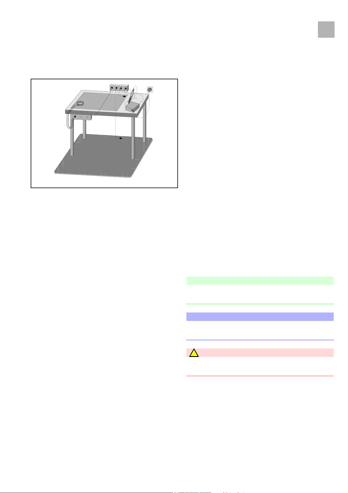
Each workstation must be equipped according to the
recommendations with the necessary static protective measures,
if ESD components or boards are handled.
Each workstation must be equipped with a conductive table
surface. The conductive surface, the soldering iron or the
soldering stations must be grounded via protective resistors.
Chairs must be of antistatic design. The floor or floor mats should
be of electrically conductive material.
Personnel must wear conductive wristbands which are connected
to a central ground potential via protective resistors, e.g. the
ground contact of a wall outlet. Furthermore it is recommended
Fig.: 0 - 1
Spare Parts and Test Equipment Only use original spare parts from the manufacturer. Do not
that personnel wear cotton clothing and electrically conductive
shoes to prevent electrostatic charge.
tamper with assembly groups which can only be exchanged
completely. The spare parts required are listed in the repair
descriptions.
Service personnel are responsible for the calibration of their test
equipment. Original test equipment can be calibrated at the
works of B. Braun. Further information is available upon request.
Setting Off Additional notes and warnings are set off as follows:
Note
Is used for additional or special notes concerning information and
working steps.
CAUTION
Is used for working steps which may result in damage to the unit,
system or to a connected device.
WARNING
!
IS USED FOR WORKING STEPS WHICH MAY RESULT IN PERSONAL
INJURY.
Perfusor® compact, 2.1 gb 0- 7

2.1
0
Important Preliminary Remarks
References to chapters are shown as follows
(see „Setting Off“ ➨ p. 0 - 7)
References to figures and tables are shown as follows
Fig.: 2 - 3 or Table 2 - 1
References to item numbers in figures are shown as follows
(Fig.: 1 - 1 / Item 1)
In this case “Fig.: 1 - 1“ is the figure number and “Item 1“ the item
number within the figure.
When the Service Manual is stored as pdf-file, these references
are displayed green. Click with the mouse button on a reference
to jump to the corresponding source.
Menu commands are described as:
Menu
File
.
List of Abbreviations Abbreviations which are not generally known, but are used in this
manual, are listed below.
A-Module Analog Module
E-Module Electronic Module
ESD Electrostatic Discharge
IfU Instructions for Use
LCD Liquid Crystal Display
MFC Multi-Function Connector
PS-Module Power Supply Module
TSC Technical Safety Checks
TEMP Temperature
0- 8 Perfusor® compact, 2.1 gb

0 - 10
3.1
0-Contact Persons
0
Technical Training Via local representative.
Entry for Technical Training Application for a technical training course must be made via the
responsible representative.
Ordering of Spare Parts and Test Equipment Please contact your local B. Braun subsidary.
International Technicians (Intercompany)
Irene Marchel
Fax: +49 (0) 5661 / 75 - 38 57
e-mail: irene.marchel@bbraun.com
Service Hotline Martin Heusner
Phone: +49 (0) 56 61 71 - 35 25
Fax: +49 (0) 56 61 71 - 35 26
E-Mail: martin.heusner@bbraun.com
Return of Spare Parts and Test Equipment B. Braun Melsungen AG
Schwarzenberger Weg 73-79
Wareneingang Werk C
34 212 Melsungen
Germany
Safety Officer (§ 30 MPG)
Dr. Ludwig Schütz
e-mail: ludwig.schuetz@bbraun.com
Perfusor® compact, 3.1 gb 0- 9

2.1
0
For your notes:
Contact Persons
0- 10 Perfusor® compact, 2.1 gb
1 - 4
2.1
Physical Construction
1-System Overview
The Perfusor compact is a compact, stacking, portable and
lightweight syringe pump which is used for precise dosing of
small to high volumes of fluids in infusion and alimentary
therapies.
The standard delivery rate range is 0.1 to 99.9 ml/h (in increments
of 0.1 ml/h).
All important information is displayed on an LC-display. The
device is easy to operate via the membrane keyboard. The syringes
are changed semi-automatically. The function process and
monitoring is microprocessor controlled. The Perfusor compact
has a long service life and is easy-to-service due to its modular
design. Individual modules can be replaced easily and quickly, and
the Service Program runs on a PC.
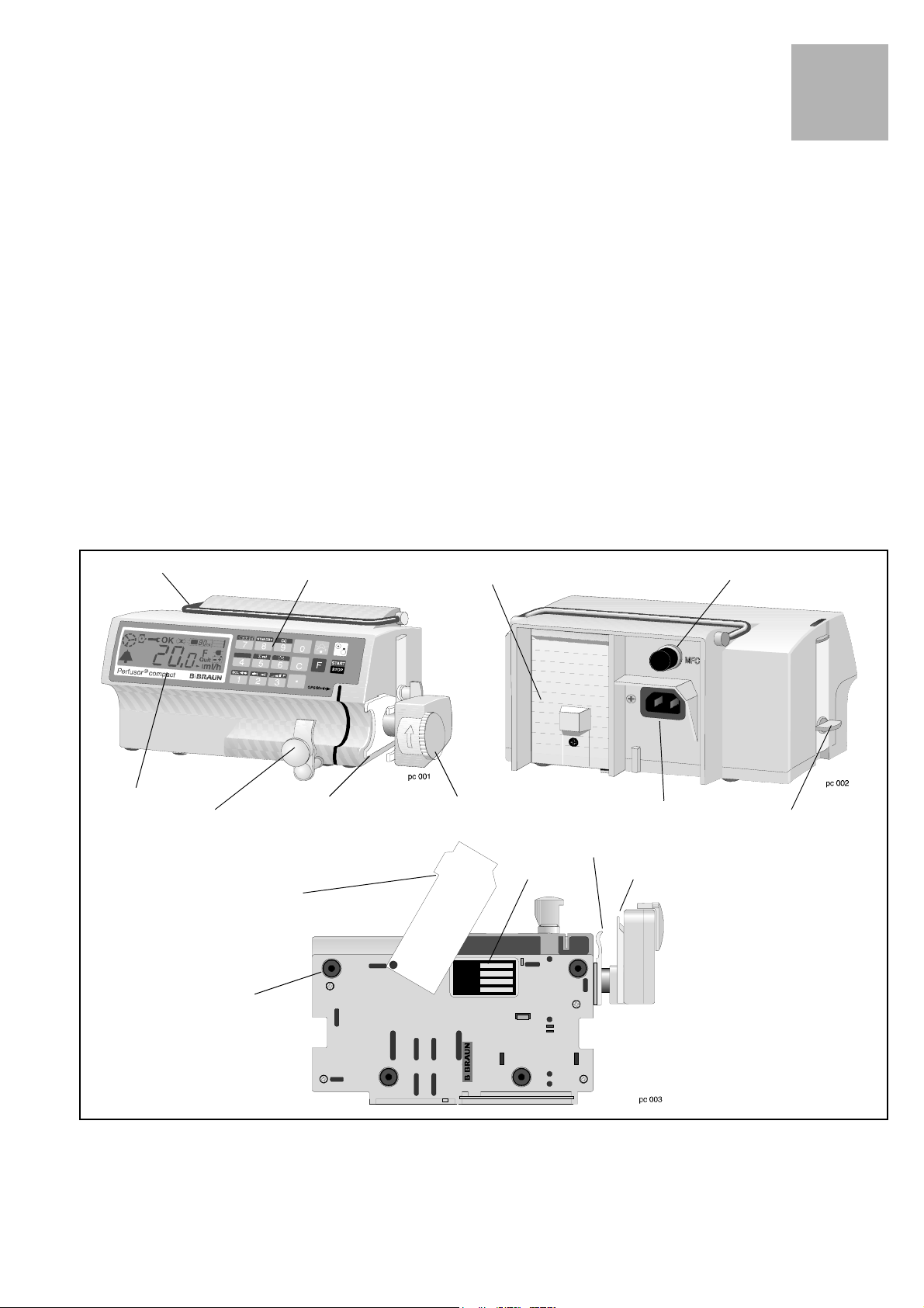
1
Carrying handle
LC display
Syringe holder
Membrane keyboard MFC socket
Axial positioner
Syringe table
and quick reference guide
Unit feet
Battery compartment
Drive head with lock
and push-button sensor
Type plate
Mains power connection
Axial positioner
Clamp
Snap-in clip
(on both sides)(on both sides)
View from below
Fig.: 1 - 1
Perfusor® compact, 2.1 gb 1- 1
2.1
1
Function
System Overview
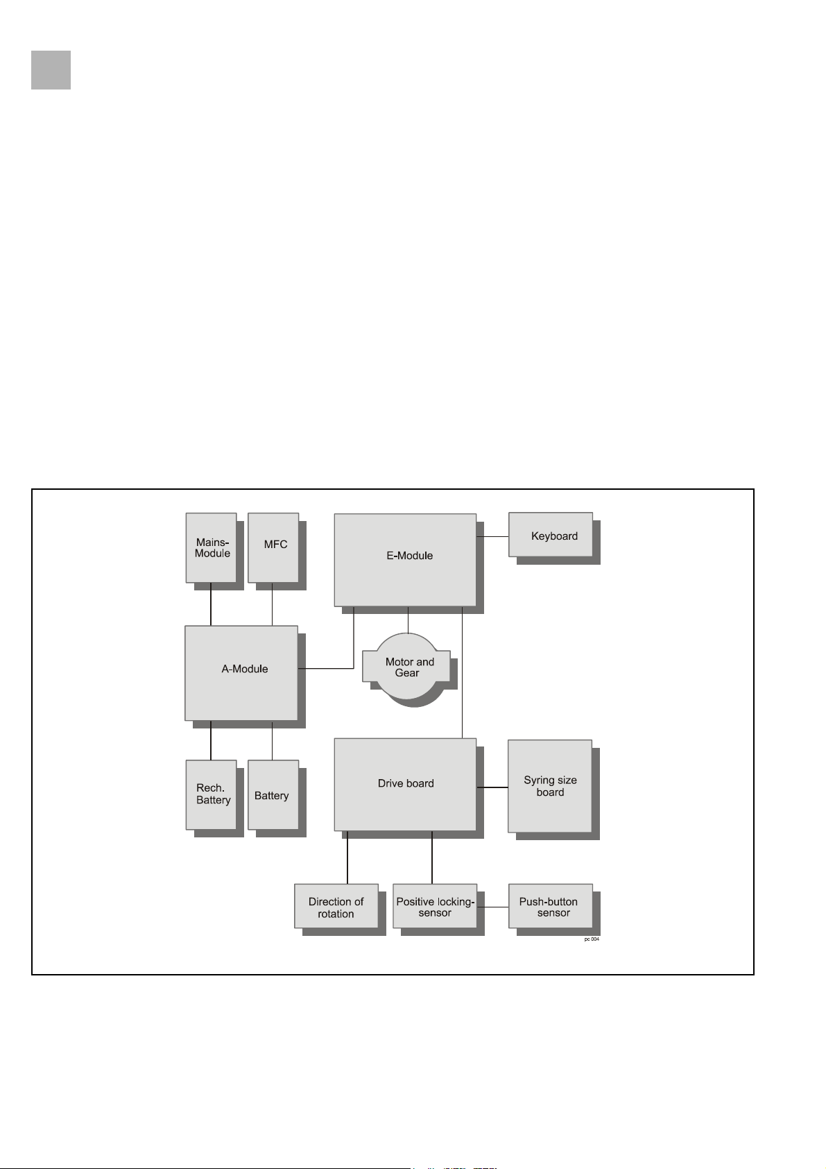
The electronics of the Perfusor compact consists of the following
components:
1. A-Module with MFC board as the central power supply and
interface
2. E-Module as operating and control unit
3. Drive unit, consisting of
- drive board with the complete sensor technology, light
barriers for syringe pre- and end-alarm, syringe size
recognition and motor operation control
- push-button sensor board for the inserted syringe
- positive locking sensor board for the frictional
connection between nut and spindle of the drive.
Fig.: 1 - 2 Block diagram
1- 2 Perfusor® compact, 2.1 gb

2.1
Accessories
System Overview
Designation Ord. No.
Unit connecting lead 200-240 V . . . . . . . . . . . . . . . . . 3450 2718
Unit connecting lead 100-240 V . . . . . . . . . . . . . . . . . 3450 5423
Pole clamp (universal clamp, rotating) . . . . . . . . . . . . 3450 9054
Battery pack . . . . . . . . . . . . . . . . . . . . . . . . . . . . . . . . . 3450 1690
1
Perfusor® compact, 2.1 gb 1- 3

2.1
1
For your notes:
System Overview
1- 4 Perfusor® compact, 2.1 gb

2 - 6
3.0
Approved Software Versions
Position 123456789
Digit PL AA00721
Revision level
Hardware identification
Software group
Hardware group
Perfusor® compact
Fig.: 2 - 1
2-Software
The software and hardware revision level is displayed on the LCdisplay when the unit is switched on. The characters on the
display must correspond with the indication on the instructions
for use.
The software can only be updated by replacing the E-Module.
Unit Software
PLAA00035.5 PLAA00070.0 (Dianet
PLAA00040.0 PLAA00071.1 (Dianet
PLAA00041.0 PLAA00072.1 (Dianet
PLAA00063.3 PLAA01070 (new hardware)
2
Star
Star
Star
)
)
)
Version Display during Switch-On Test
Extended Version Display during Switch-On Test
1. Switch on unit.
2. The following information is displayed one after the other on
screen:
888.
8
111 .
1
222.
2
555.
5
AA Reference to the instructions
for use (hard- and software group)
3. The Perfusor® compact switches over to normal operation.
1. Switch on unit.
2. Press the F button and keep the button pressed during normal
switch-on test. The following information (examples) appears
on screen after the information displayed during normal
switch-on test:
00 Hardware identification
071
1 Software version
123
4 1234 operating hours
999
9 Maintenance interval timer
3. Release the F button to exit. The Perfusor® compact switches
over to normal operation.
Perfusor® compact, 3.0 gb 2- 1

2.1
2
Software
Error Messages and Alarms
LC display Description
1 Different syringe recognition
2 Different FP- and CMP condition
3 Rate of FP- and CMP different
4 Different function mode
5 Different rate of delivery
6 Different target volume
In case of a unit malfunction a continuous signal is activated, and
the function processor displays an alarm and an error code. The
error code of the control microprocessor can be queried with the
F button. Please state both error codes if you have any questions.
Acknowledge alarm and switch device off.
Device Alarms of the Function Processor
7 Different step volume (low)
8 Different motor steps
19 State/motor state
20 Invalid normal state
21 return from PlcMain
22 Unexpected reset
28 No sync at Plc_Down
29 No sync at Plc_On
30 Different CMP/FP mode ports
31 Invalid mode ports
32 Invalid variable values
33 Error in ROM test
34 Different software version
40 Unexpected interrupt
49 Faulty sensor sync
51 Motor on during reverse run
52 Step cumulation > 10 steps
53 Illegal setting of Mot_Ok
54 Different recognition of direction of rotation
55 Reverse polarity of motor
Table 2 - 1 (Part 1 of 2)
2- 2 Perfusor® compact, 2.1 gb

2.1
LC display Description
56 Invalid syringe
57 Overflow of motor step counter
59 No sync at Mot_Test
61 Different SW button NEC<>H8
62 Timeout KBD watchdog
63 Error in switch-on test
70 Control timer overflow (int)
71 Control timer underflow
72 Control timer overflow
73 100 ms cycle overflow
75 Tim_WaitUntil overflow
81 Error upon reading of EEPROM
83 Error of EEP data consistency
Software
2
84 Ad difference between NEC/H8
85 Bw difference between NEC/H8
86 Md difference between NEC/H8
90 Syringe state in Oper_Syr
91 Set syringe type
92 Consistency error
93 Difference between setting and display
94 Timer synchronization
100 Division by zero
101 Illegal zero pointer
102 Illegal switch to default
105 No contact to NEC in OFF
110 Alarm on CMP side
111 ... 119 Motor test 1 ... 9
120 Motor current flow in OFF
121 Battery discharged during test
125 ASSERT error
126 Alarm synchron. (fault occurrence)
127 Alarm synchron. (back-to-normal)
248 Motor test 8 from NEC
251 NEC: Battery discharged during test
Table 2 - 1 (Part 2 of 2)
Perfusor® compact, 2.1 gb 2- 3

2.1
2
LC display Description
128 Unexpected reset
129 Unexpected hardware interrupt
130 Access of zero pointer
131 Attempted division by zero
132 Internal software error
134 State/motor state
135 Invalid variable values
136 Invalid operating condition
137 Illegal mode – port value
138 H8 indicates GA F14_H8GA_K16
150 Different software versions
Software
Device alarms of the control microprocessor
151 Double CRC error
153 Different states
154 Different rates
155 Different F-mode
156 Different mode values
157 Different alarm recognition
158 Different alarm clearance
159 Err. current volume
160 Err. preselected volume
161 Err. volume per step
170 Sensor sync. failed
171 ... 174 Sensor - dark test error
180 ROM test error
181 RAM test error
182 Keyboard test error column
183 Dynamic memory test
184 Motor test no sync
185 Keyboard test error
186 Timer test error
187 CPU test error
188 Battery test error
191 Different software buttons
Table 2 - 2 (Part 1 of 2)
2- 4 Perfusor® compact, 2.1 gb

2.1
LC display Description
192 Keyboard timeout error
200 Cycle > 100 ms
202 Time > Until
203 Watchdog interrupt
204 Error when waiting for H8
205 Time-out when switching H8 on
206 Time-out when switching H8 off
207 No sync at Plc_Down
208 No sync at Plc_On
209 CMP/FP timer – end sync error
220 Different phases (busy)
221 Different phases (idle)
222 Motor on at reverse steps
Software
2
223 Too many pending steps
224 Motor current error
225 Error of motor step number
226 Reverse polarity of motor
227 Motor steps overflow
230 Different syringe recognition
231 CMP/FP syringe state
232 CMP/FP syringe type set
241 ... 249 Motor test 1 ... 9 errors
250 Motor ON in OFF-mode
251 Battery voltage low
Table 2 - 2 (Part 2 of 2)
Note
Operating alarms are specified in the instructions for use.
Perfusor® compact, 2.1 gb 2- 5

2.1
2
For your notes:
Software
2- 6 Perfusor® compact, 2.1 gb

3 - 18
3.0
Software Compatibility
3-Service Program
Designation Ord. No.
Interface cable . . . . . . . . . . . . . . . . . . . . . . . . . . . . . . . 0871 1661
Compatibility
Unit Software Service Program Ord. - No.
PLAA00035.5 5.3502 . . . . . . . . . . . On request
PLAA00040.0 5.5004
PLAA00041.0 5.5004
PLAA00063.3 2.1.0.1 . . . . . . . . . . . 3452 0474
PLAA00070.0 (Dianet
PLAA00071.1 (Dianet
PLAA00072.1 (Dianet
PLAA01070 (new hardware) 2.1.0.1 . . . . . . . . . . . 3452 0474
Star
) 2.1.0.1 . . . . . . . . . . . 3452 0474
Star
) 2.1.0.1 . . . . . . . . . . . 3452 0474
Star
) 2.1.0.1 . . . . . . . . . . . 3452 0474
†
. . . . . . . . . . 3452 0474
†
. . . . . . . . . . 3452 0474
3
Introduction
Note
The following description refers to the versions 5.5004 and
2.1.0.1. of the Service Program.
The relevant version is given in square brackets in the illustrations
of each user interface and where the description contains
differences.
The Service Program runs in a user-friendly way on a PC. All
functions are easy to operate in the pulldown-menus as in
Windows.
WARNING
!
Service mode is only authorized for service tasks.
DANGER OF INJURY IF USED ON THE PATIENT!
- Never connect the MFC service connector or the service cable
when a patient is connected to the unit!
- First switch the unit off before any further use after working
with the MFC service connector.
- Carry out a check according to the procedural instructions for
inspection after the Service Program was run. (see
“Procedural Instructions for Inspection after Modifications
via the Service Program” ➨ p. 3 - 13).
†
The previous version 5.5004 is included in the installation package for 2.1.0.1.
Perfusor® compact, 3.0 gb 3- 1
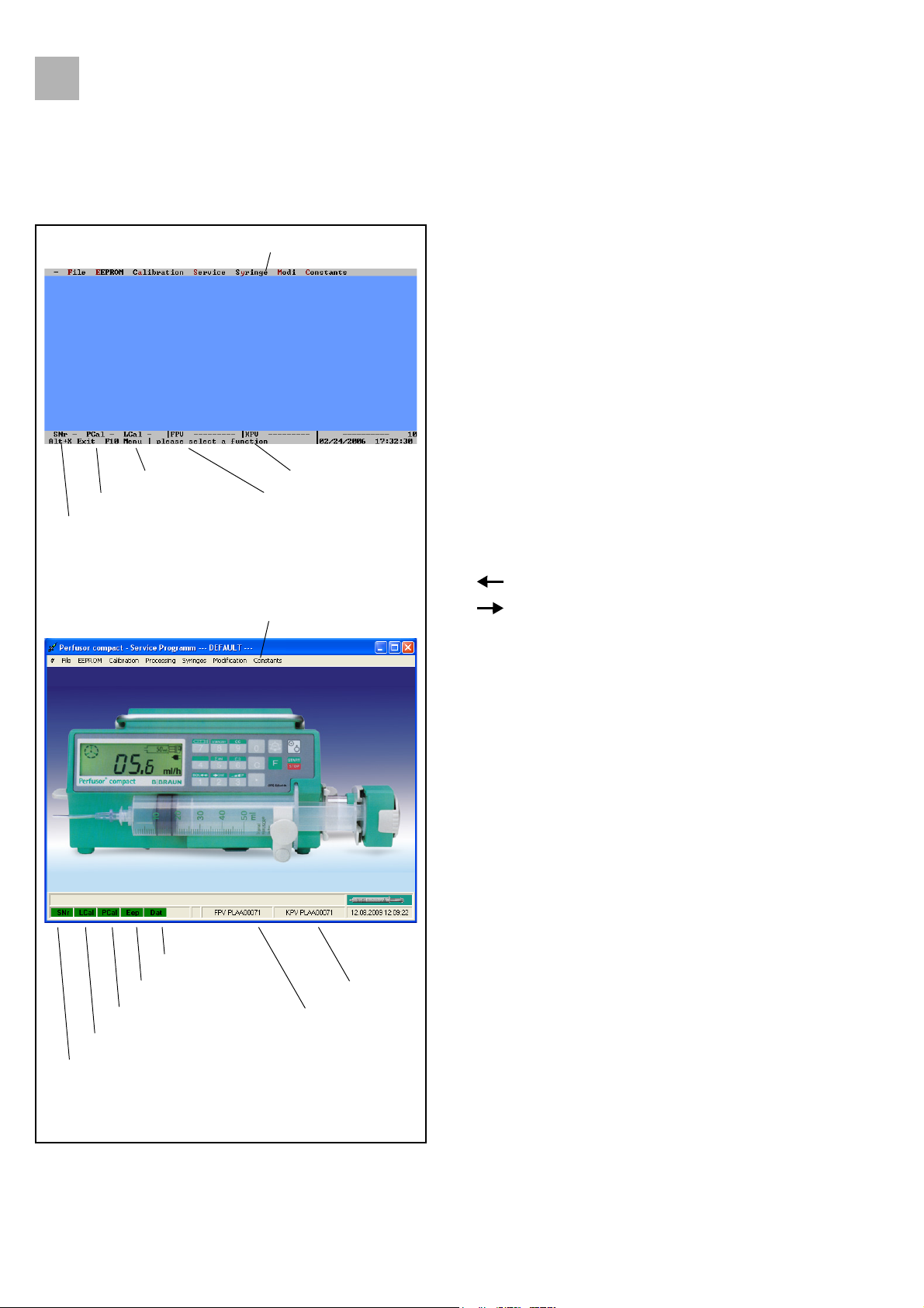
e
3.0
3
[Version 5.5004]
Service Program
Length calibration
Pressure calibration
Serial number
Selection menu
Control microprocessor
Function processor
The special keys on the keyboard have the following functions:
- ESC [Version 5.5004] Cancel
- F1 Connect
- F2 Default EEPROM
- F3 Read-out EEPROM
- F4 Serial number
- F5 Length calibration
- F6 Pressure calibration
- F7 Write EEPROM
- F8 Save
- Alt + A Alternatively: Alt + bold
- Alt + F4 [Version 2.1.0.1] Exit
- Tab to jump to next field
[Version 2.1.0.1] Selection menu
Data saved
EEPROM written
Pressure calibration
Control microproc
Function processor
- to move the cursor
- to move the cursor
When the Service Program is installed and the PC is connected to
the Perfusor compact, the following functions can be executed:
- Drive calibration
- Reading / loading pump data
- Displaying service values
- Displaying and changing parameters
- Documentation of pump hardware modifications
- Saving all data to a diskette, hard disk, or similar
Length calibration
Serial number
Fig.: 3 - 1 Overview of user interfaces
3- 2 Perfusor® compact, 3.0 gb
3.0
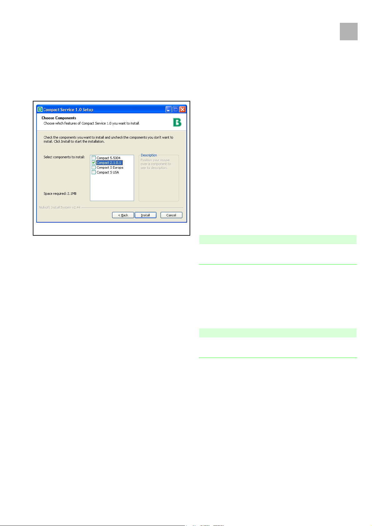
Fig.: 3 - 2
Service Program
Installation
1. Insert the CD.
2. Start the File Manager or Windows Explorer.
3. Start Setup.exe with a double-click.
4. Select language for installation and confirm with
5. In the Welcome dialog box start installation with
6. Accept licenses with
7. Select a program version and continue with
(Fig.: 3 - 2).
8. During installation the program creates the directory
C:\Programme\Serviceprogramm xxx Perfusor compact\
automatically (xxx = version number). Calibration and default
data are also saved in this directory (if no other directory is
specified). The directory name can be changed without any
problems.
IAgree
.
Install
OK
.
Next
3
.
Note
The system configuration of the PC is not changed when the
Service Program was installed.
Uninstalling
1. To uninstall the service program, delete file Plc_serv.exe
[Version 5.5004] or PcsCompact.exe [Version 2.1.0.1].
To uninstall the service program incl. the service program
directory in full, double-click file uninst.exe to start it.
Note
If the entire directory \Serviceprogramm xxx Perfusor compact\ is
deleted, all unit data is deleted from the PC.
Configuration
1. Select the language and interface with the
File➨Configuration
screen display [Version 5.5004].
2. Acknowledge with
menu item. Also select the desired
OK
.
Perfusor® compact, 3.0 gb 3- 3
3.0
3
Service Program
Working with the Service Program
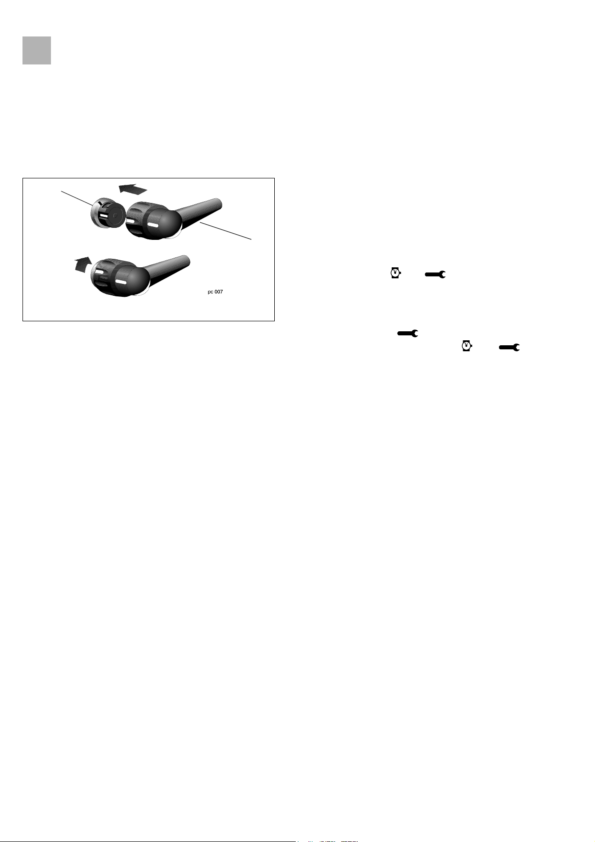
1
Fig.: 3 - 3
Legend of fig. 3 - 3:
ItemDesignation
1 MFC connector on the unit
2 MFC service cable
Preparation
1. Connect service cable (Fig.: 3 - 3 / Item 2) to MFC connector
(Fig.: 3 - 3 / Item 1) of unit and to PC serial port (COM 1 or
COM 2).
2. Connect mains power cable to the unit.
2
3. Start the Service Program on the PC.
4. [Version 5.5004]: To start communication, press the ON key
on the Perfusor® compact until "Release On/Off key" is
displayed on the PC. and are displayed on the LC
display.
[Version 2.1.0.1]: To start communication, select menu item
File ➨ Connect
compact pressed until disappears from the LC display.
After connection has been established and are
displayed.
Display / Save the Unit Settings
, then keep the On key on the Perfusor®
1. Menu item
2. Menu item
3. Menu item
4. [Version 5.5004]: Select menu item
Data
types
new E-Module).
[Version 2.1.0.1]: Select menu item
Modification data
selection
any modification (e.g. new E-module) or print out with
Print
Adjust Unit Settings
1. Menu item
2. Menu item
3. Desired modifications / display, please see:
-
Service ➨ Service Values
Processing ➨ Processing values
File ➨ Connect
EEPROM
File ➨ Save
➨
Read
.
.
.
Modi ➨ Modification
and menu item
. Note down parameters prior to any modification (e.g.
Syringe ➨ Syringe selection
Modification ➨
or
Syringe types
.
File ➨ Connect
EEPROM ➨ Read
and menu item
. Note down parameters prior to
.
[Version 5.5004] or
Syringes ➨ Syringe
.
[Version 2.1.0.1]
or
Syringe
File ➨
-
Modi
➨
Modification Data
Modification ➨ Modification data
-
Calibration ➨ Pressure calibration
bolus rate change)
3- 4 Perfusor® compact, 3.0 gb
[Version 5.5004] or
[Version 2.1.0.1]
(required in case of

3.0
Service Program
-
Syringes ➨ Syringe selection
-
Constants ➨ Service interval
4. Menu item
Menu item
5. Enter the user number 0 upon query.
6. Check unit according to the procedure instructions for
inspection (see “Procedural Instructions for Inspection after
Modifications via the Service Program” ➨ p. 3 - 13).
Unit Calibration
The unit must be calibrated (see “Unit Calibration” ➨ p. 3 - 16)
after the E-Module or the drive has been replaced or the bolus
rate changed.
EEPROM ➨ Write
File ➨ Save
saves the data to the hard disk.
transmits data to the device.
3
What To Do If ... (Trouble Shooting)
Defaut Data
The Service Program contains the Default.dat file with the factory
settings of the unit. These values can be adjusted via the Syringe
or Modes menu if required.
Max. delivery rate (basal rate) . . . . . . . . . . . . . . . . . . . . 99.9 ml/h
Bolus rate . . . . . . . . . . . . . . . . . . . . . . . . . . . . . . . . . . . . . . 800 ml/h
Staff call [Version 5.5004]. . . . . . . . . . dynamic without off alarm
[Version 2.1.0.1] . . . . . . . . . . . . . . . . dynamic with pre-alarm
Alarm tone[Version 5.5004] . . . . . . . . . . . . 0 (3 Hz interval tone)
Tone when alarms output [Version 2.1.0.1] . . . . . . . . . . . . . . .3 Hz
Tone when pre-alarms output [Version 2.1.0.1] . . . . . . . . . . static
Pressure stage. . . . . . . . . . . . . . . . . . . . . . . . . . . . . . . . . . . . . . . . . 3
Dianet address [Version 5.5004] . . . . . . . . . . . . . . . . . . . . . . . . . 1
Syringe selection . . . . . . . . . . . . . . . . . . . . . . . . . . . . . . . . . . . Table
Service interval. . . . . . . . . . . . . . . . . . . . . . . . . . . . . . . . .20440 hrs.
... the length calibration does not start?
Could communication be started successfully? Does the motor
still not start?
Then: Select Termination. Switch off pump. Repeat
communication start. Switch pump on again.
Perfusor® compact, 3.0 gb 3- 5

3.0
3
Service Program
... the communication to the pump is missing?
Is the service cable connection okay? Is the MFC correctly
connected?
Then: Select Termination. Switch off pump.
Repeat communication start. Switch pump on again.
... the communication cannot be started?
Compatibility of service software and unit software checked? Was
the setting with the
item selected correctly? Is the service cable connection okay? Is
the MFC correctly connected?
... the communication starts and is then interrupted?
Then: Press the ON-key on the Perfusor compact until the
symbols and disappear.
File ➨ Configuration
(COM 1 or 2) menu
... the unit does not accept any syringe after a service was
carried out?
Is syringe selection set to "free type", but "free type" was not
loaded?
Then: Set syringe selection to table / OPS or load corresponding
syringe.
... Problems under Windows 2000 / XP [Version 2.1.0.1]
1. Data transmission during reading and writing EEPROM takes
a long time, sporadic program crashes.
- Change settings in file C:\WINNT\System32\CONFIG.NT
- This file can be modified with the program editor, for
example. Change setting for "files=40" (last line) to
"files=99". Do not forget to save.
2. Error message for syringe recognition test during operation.
- Change setting for COM interface in the Control Panel.
- To do this, open the Device Manager and find setting for
the COM interface.
- Under "Port Settings -> Advanced," activate or
deactivate the "Use FIFO Buffer" field.
- This setting can very depending on the hardware.
3- 6 Perfusor® compact, 3.0 gb
 Loading...