

Page 1

Service Documentation Market Release 10/99
Braun exact power EP 100, 80, 60 5601
5601
Page 2
BINC Rev: 9/99 Service Documentation
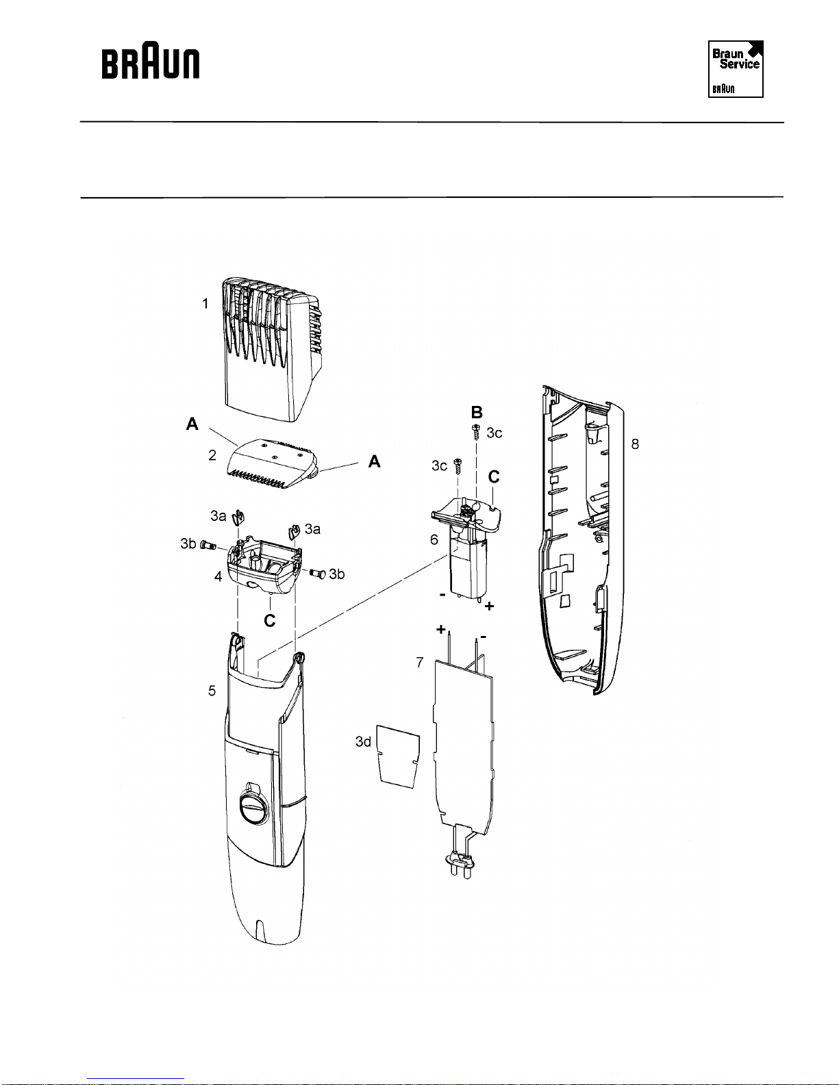
Exploded Drawing
BAG Rev: 9/99 5601
5601 - 2
Page 3

BINC Rev: 9/99 Service Documentation
Spare Parts List
BAG Rev: 9/99 5601
Pos. No. Part Description Part Number
1 Comb attachment 5601621
2 Cutter set 5601622
3 Small parts set 5601623
4 Swivel frame 5601632
5 Housing front part (silver) 5601633
6 Motor 5601624
7 PCB (1 hr) 5601625
8 Housing back part 5601634
Coiled cord 5002704
Cleaning brush 5503120
Case 7000062
5601 - 3
Page 4

BINC Rev: 9/99 Service Documentation
Service Information
BAG Rev: 9/99 5601
Technical Data Principle Rechargeable / cord shaver
Nominal voltage 120 VAC
Nominal frequency 50 - 60 Hz
Housing Plastic material
Cutting system Switchable double cutting system
(21 resp. 33 mm width)
Switch function Central sliding switch with integrated "speed"-shifting
and button for lock function
Separate memory slide for 7 beard-length positions
(1 - 2 - 3 - 6 - 9 - 12 and 16 mm)
Drive 1.2 V DC motor
Revolutions switchable to two positions
Position 1: approx. 4.760 r.p.m. (min.)
approx. 6.120 r.p.m. (max.)
Position 2: approx. 5.600 r.p.m. (min.)
approx. 6.800 r.p.m (max.)
(after a recharging time of least 3 minutes and with
greased cutting system)
Power transmision Via eccenter directly onto the shaving system
Power supply Via a built in, rechargeable NH-battery, resp. a built-in
battery recharger
Charging time EP 100 approx. 1 hour
EP 80 approx. 8 hours
EP 60 approx. 16 hours
Power consumption EP 100 approx. 4 watts
EP 80 approx. 5 watts
EP 60 approx. 1,35 watts
Charging of the shaver Is indicated by a green lamp
Operating capacity after full recharge
5601 - 4
approx. 30 cutting minutes
Page 5

BINC Rev: 9/99 Service Documentation
Service Information
BAG Rev: 9/99 5601
Dismantling Comb attachment (1) Set sliding switch in "0" position.
Pull off comb attachment by snap action.
Cutter set (2) To be snapped out by pressing buttons "A".
Swivel frame (4) Insert a small Torx screwdriver into the hole of the
springs (3a) and snap them out by pushing towards the
inside of the frame. Remove the pin (3b).
Unhinge and remove swivel frame (4) (see diagram
below).
Housing Unscrew screw "B" (3c) of the housing back part (8).
Motor (6) Remove the screw (3c) in the housing font part (5).
PCB (7) Remove and snap out plug connector.
5601 - 5
Press together the housing front part (5) in the area of
the bearing pin; then, insert a wide-bladed screwdriver
into the guide slot on the left side of the sliding switch
and unhinge the housing snaps. Now, pull apart the
housing halves.
Unsolder the connecting wires to the PCB (7).
Page 6

BINC: 9/99 Service Documentation
Service Information
BAG: 9/99 5601
Reassembly The reassembly is done in reversed order.
Please pay attention to the following points:
Motor (6) Insert the motor (6) into the housing front part (5) in
such a way that the indentations for the swivel head
snaps on the left side of the cover point towards the
memory slider. Then, fix with screw (3c).
PCB (7) Before inserting the PCB, please make sure that the
contact slider is placed correctly into the connectinglink, gripping into the carrier of the memory slider.
Press the connecting plug into the supporting clamps of
the socket housing. Insert the PCB.
Solder the connecting wires to the motor; pay attention
to the correct poles!
(Solder the plus wire (red) to the motor connection
marked with a red dot).
Housing When pressing together the housing halves (5 + 8), the
guides of the central and memory switches must grip
into the housing lower part.
Screw the screw (3d) into the housing back part.
Swivel frame (4) Insert the swivel frame (4) into the pick-ups, the spring
notch "C" being on the side of the memory slider.
Insert the pin (3b).
Push the springs (3a) onto the pins (3b) from the
frame's inside.
5601 - 6
Page 7

BINC: 9/99 Service Documentation
Service Information
BAG: 9/99 5601
Hint To facilitate the reassembly of the springs (3a), and
nail (head dia. 4 mm) can be clamped in a vice, the
device being supported with the pin head (see diagram).
Cutter set (2) Press buttons "A" and insert them; pay attention to the
correct sides.
Check functions.
Checking the PCB
• Let the shaver run empty from normal operation.
• Connect to power supply. (Depending on the shaver version, the power
consumption is approx. 1 - 5 watts).
• Recharge shaver approx. 5 minutes. (The green lamp must burn permanently).
• Disconnect shaver from the mains and measure voltage via battery.
The voltage of the cell must exceed 1.2 V. If this value is indicated, the PCB is
in order.
Maintenance note To maintain the optimum cutting performance of the beard trimmer and the
optimum life of the battery it is absolutely necessary to clean and to grease the
cutter set (2) regularly.
Please proceed as follows:
• Unlock and remove cutter set by pressing buttons "A".
• Clean with the brush.
• Apply a drop of resin-free oil (e.g. sewing machine oil) between the cutters
and the sliding spring bearings in the back.
• Reassemble the cutter set and check the electrical function.
Attention
Used batteries must not be disposed of in the household waste, but at
appropriate disposal sites.
5601 - 7
 Loading...