

Braun D521 series, D521.04, D521.02, D521.14, D521.10 Product Manual
...
E16
D521-Manual_EN_Rev07 2017_05_26 Page 1 of 31
Manual
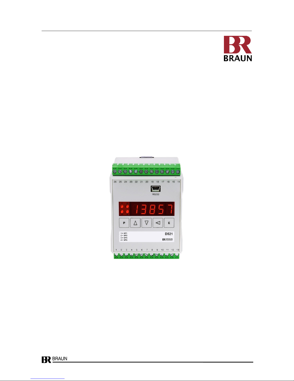
Series D521
(Revision 07)
Product Manual
Original Instructions
valid for versions
D521.02 2 Relay Outputs as SPDT relays
D521.04 4 Relay Outputs (2 as SPDT relays, 2 as PhotoMOS relays)
D521.10 1 Analog Output
D521.12 2 Relay Outputs as SPDT relays + 1 Analog Output
D521.14 4 Relay Outputs (2 as SPDT relays, 2 as PhotoMOS relays) + 1 Analog Output
D521 Front View
Single Channel Speed Monitor
for
increased safety requirements up to SIL1

D521-Manual_EN_Rev07 2017_05_26 Page 2 of 31
Table of Contents
Content Page
Table of Contents ........................................................................................................................................................ 2
1 Technical Specifications .................................................................................................................................... 3
2 Description ......................................................................................................................................................... 4
2.1 Function ...................................................................................................................................................... 4
2.2 Display and Operating Elements ................................................................................................................. 4
2.3 Display ........................................................................................................................................................ 4
2.4 Status LEDs ................................................................................................................................................. 4
2.5 Functions during normal operation .............................................................................................................. 4
2.6 Event Codes on Display .............................................................................................................................. 4
2.7 Measuring Principle ..................................................................................................................................... 5
2.8 Performance at Signal Break....................................................................................................................... 5
2.9 Signal Input V-Path (volts) Terminal 14........................................................................................................ 5
2.10 Signal Input mV-Path (millivolts) Terminal 15 .............................................................................................. 5
2.11 Sensor monitoring ....................................................................................................................................... 5
2.12 Reserved ..................................................................................................................................................... 5
2.13 Alarms ......................................................................................................................................................... 6
2.14 Analog Output (D521.10, D521.12, D521.14).............................................................................................. 6
2.15 Signal Pulse Output 1 .................................................................................................................................. 6
2.16 Signal Pulse Output 2 .................................................................................................................................. 6
3 Model No. Code .................................................................................................................................................. 7
4 Parameters ......................................................................................................................................................... 8
4.1 Summary of parameters and their default values as set on delivery ........................................................... 8
4.2 Setting the Parameters via RS232-Interface ................................ ............................................................... 9
4.3 Setting the parameters via Front Keyboard ............................................................................................... 10
5 Description of Parameters and their Settings ............................................................................................... 11
5.1 Default Values at delivery .......................................................................................................................... 21
6 Installation ................................................................................................................................ ........................ 22
7 Safety Notes for Installation and Operation ................................................................................................... 23
7.1 Safety Notes for Installation ....................................................................................................................... 23
7.1.1 General Instructions.......................................................................................................................... 23
7.1.2 EMI ................................................................................................................................................... 23
7.1.3 Safety Notes for Operation ............................................................................................................... 23
7.2 Safety Notes for SIL2 Speed applications in hazardous areas .................................................................. 24
7.2.1 Monitoring the Speed Signal ............................................................................................................. 24
7.2.2 Use of alarms SP1 to SP4 ................................................................................................................ 24
7.2.3 Monitoring the Speed during operation ................................ ............................................................. 24
7.2.4 Safety Notes for Standstill alarm SP3 ............................................................................................... 24
7.3 Dimensions................................................................................................................................................ 25
7.4 Function diagram and connections of D521 .............................................................................................. 26
7.5 Connections of measuring signals to input ................................................................................................ 27
7.6 Connection of BRAUN sensors ................................................................................................................. 28
7.7 Connection of A5S1.. with D461 to D521 .................................................................................................. 29
8 Safety Data ........................................................................................................................................................ 30
8.1 Safety Data of Measuring Chain D521-A5S0 resp. D521-D461-A5S1 ...................................................... 30
9 Revision notes.................................................................................................................................................. 31

D521-Manual_EN_Rev07 2017_05_26 Page 3 of 31
1 Technical Specifications
Design Snap-on-track plastic enclosure for 35 mm rail,
field mounting enclosure (Option -G) on request.
Dimensions: see chapter 7.3
Weight: standard version approx. 0.3 kg, option –G approx. 1.0 kg
Installation Conditions Ambient temperature in operation: 0°C...+60°C
Ambient temperature in storage: -40°C...+85°C
Electrical insulation grade: I
Voltage grade: I
Protection grade standard version: terminals IP20
enclosure IP 40
Protection grade option -G: IP65
Power Supply Supply voltage: 20...265 volts uc
Power consumption: 5 W resp. 5 VA
Signal input and Response levels: see chapter 2.9 resp. 2.10
Sensor supply Input impedance (I): 100 kohms
Sensor supply: approx. 13 volts, max. 60 mamps resp.
8 volts with 1k load resistor (incorporated)
Sequence: 5 msec - 9.999 sec (programmable)
Measurement Accuracy: ± 0.005 % of measurement, ± 1 in LSD
Relay Outputs 2 alarm outputs with SPDT relay contacts
(Versions D521.02 Handling capacity: Voltage max 250 volts AC/DC (minimum 10 millivolts)
D521.04 Current max 2 amp AC, 1 amp DC (minimum 10 µamp)
D521.12 Power rating max 100 W, 250 VA into ohmic load only
D521.14) (inductive loads need overload protection)
(Versions D521.04 2 additional alarm outputs with PhotoMOS relay contacts
D521.14) Handling capacity: Voltage max 60 volts DC (minimum 10 millivolts)
Current max 0.1 amp DC (minimum 10 µamp)
Analog Output Isolated and programmable with range 0/2-10volts / 0/4-20mamp
(Versions D521.10 Resolution: 12 bit
D521.12 Max. load: 750 ohms
D521.14) Linearity error: < 0.1 %
Temperature stability: ±0,02 %/°C within a range of 0...60°C.
Display 5 digits LED red, 10 mm, with adjustable decimal point
Programming Interface RS 232 (only with adapter cable L3D01 and interface software IS-RS232-S)
D521-Manual_EN_Rev07 2017_05_26 Page 4 of 31
2 Description
2.1 Function
The device measures the speed of rotating equipment such as turbines, compressors or expanders and monitors it versus setpoints and converts it into an analog output.
Parameters may be set via front keyboard and display or via the RS-232 data interface.
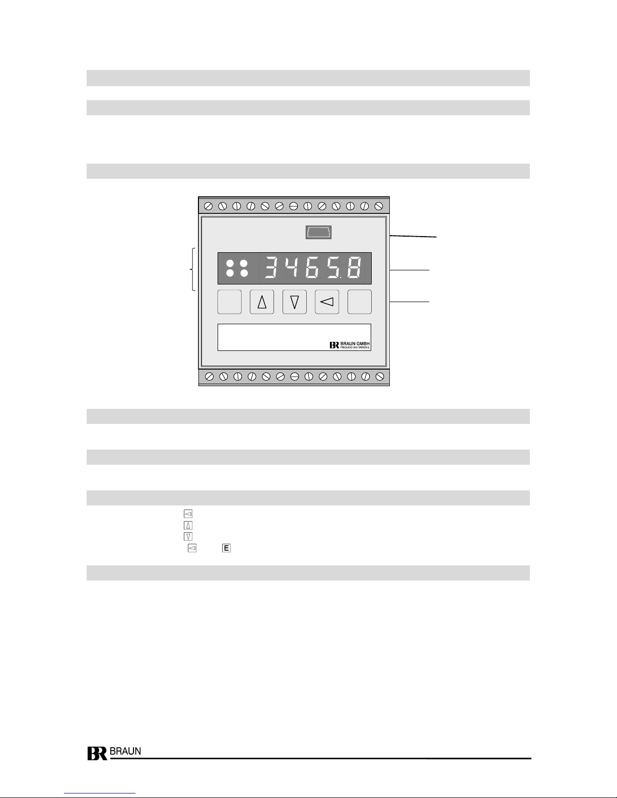
2.2 Display and Operating Elements
2.3 Display
During normal operation, the speed will be displayed.
2.4 Status LEDs
LEDs 1 to 4 are on if the corresponding output relays of SP1 to SP4 are energized.
2.5 Functions during normal operation
Key : Reset of latched max./min. -values speed
Key : Display of latched max. speed
Key : Display of latched min. speed
Keys and : Reset of latched alarms
2.6 Event Codes on Display
-E1- : Wrong code figure in step P00.00
SE-01 : Sensor fault or signal lead break
Display
Data-Interface
LEDs
1 to 4
Operation
Keys
1
RS232
D521
2
3
4
26
25
24
23
22
21
20
19
18
17
16
15
14 1 2 3 4 5 6 7 8 9 10
11
12
13
P
E

D521-Manual_EN_Rev07 2017_05_26 Page 5 of 31
2.7 Measuring Principle
Measurement is based on the frequency of the pulse sequence representing the speed. Basic
quantity is the time between one or more of its pulses. An automatic function determines this
number, in order to maintain a minimum period of time for every measurement to be extended
over. This time minimum is programmable to 5 milliseconds or more, thus establishing a corresponding averaging and stabilization of measurements.
The corresponding speed value in terms of RPM, by which the display, the alarm circuit, and the
analog output are reading, computes from these measurements. This process further considers
the programmed application data (relation between machine speed and signal frequency).
2.8 Performance at Signal Break
In normal operation, the function closely tracks the input sequence, with the programmed
performance. After a sudden interrupt of the input pulses, the unit reduces the readings following
an automatic step-down sequence. This starts as fast as the most recent measuring sequence
before interrupt but then decreases slower and slower (reciprocal) until it meets the programmed
low end.
2.9 Signal Input V-Path (volts) Terminal 14
Accepting any sensor which meets these conditions:
- High Level path:
Response level on/off : >7/<5 volts DC with programmable hysteresis
Maximum voltage: 100 volts
Input impedance: 100 kOhm
Frequency range: 0 … 50 kHz
Sensor supply: approx. 13 volts / 60 mamps.
- 2-leads NAMUR sensors DIN 19234 (if programmed):
Current level on/off >2.0 mamps / < 1,2 mamps with programmable hysteresis
Sensor supply: 8 volts with 1 kOhm load resistor (incorporated).
Corresponding BRAUN Sensors listed in Wiring Diagrams on page 26.
2.10 Signal Input mV-Path (millivolts) Terminal 15
Accepting low level sensors or such with superposed DC-level, or such missing the above
specified V-levels. Sensitivity (min amplitude required) depending on signal frequency (with
sinusoidal waveform)
500 millivolts RMS between 0.1 Hz … 1 Hz
50 millivolts RMS between 1 Hz … 10 kHz
500 millivolts RMS above 10 kHz
Max voltage 50 volts with max ± 35 volts DC superposed.
Input impedance approx. 50 kOhm
2.11 Sensor monitoring
Monitoring sensor current drain, output voltage, and signal activity (if applicable to sensor type).
2.12 Reserved

D521-Manual_EN_Rev07 2017_05_26 Page 6 of 31
2.13 Alarms
Two (optionally four) individual setpoints control an own signal output (2 as SPDT relays
contacts, 2 as option with PhotoMOS relay contacts). Each with individually programmable
response characteristics, and each with programmable starter.
2.14 Analog Output (D521.10, D521.12, D521.14)
Output signal isolated and linear as current 0/4… 20 mamps into 750 Ohms max load, or voltage 0/2 volts …10 volts under max. 10 mamps load.
Live zero as well as high and low end of conversion programmable.
2.15 Signal Pulse Output 1
Repeating the input pulse signals (undivided) by the same sequence, as square wave pulses of
approx. 10 volts and 1 kOhm source impedance. Same reference as input.
2.16 Signal Pulse Output 2
Isolated (passive) output by optocoupler, for max load 30 volt / 10 mamps. Pulse sequence as
reduced by the input pulse divider. Max output frequency 12 kHz (at a 1:1 duty input signal).
Output must be powered externally.

D521-Manual_EN_Rev07 2017_05_26 Page 7 of 31
3 Model No. Code
No.
Analog Output
No. of Alarms
D521.02
no
2 (2 SPDT relay outputs)
D521.04
no
4 (2 SPDT relay outputs + 2 PhotoMOS relay outputs)
D521.10
yes
0 none
D521.12
yes
2 (2 SPDT relay outputs)
D521.14
yes
4 (2 SPDT relay outputs + 2 PhotoMOS relay outputs)

D521-Manual_EN_Rev07 2017_05_26 Page 8 of 31
4 Parameters
4.1 Summary of parameters and their default values as set on delivery
Param.
No.
Default
value
Parameter Function
P00.xx
Code figure, Parameter Lock, Front side Reset of Alarms
P00.00
0000
Code figure
.01
0000
New code figure
.02
0
Front side Parameter Lock : 0: locked / 1: enabled
.03
0000
Minimum Measuring Period (in xxxx milliseconds)
.04
000
Starter Time Period (in xxx sec)
P01.xx
Input Scaling
P01.00
0
Decimals of input frequency
.01
00100
Value of nominal input frequency in Hz
.02
0
Decimals of speed value
.03
00100
Nominal speed (e.g. in RPM)
.04
00001
Lower limit of the speed range
.05
0
Hysteresis of input response level (0 : A5S sensor, 1 : MPU or NAMUR sensor)
.06
1
Reserved for future applications
.07
0
Reserved for future applications
.08
1
Sensor monitoring: 0: off / 1: on / 2: on, latched
.09
1
Mode of sensor monitoring: 0: none / 1: current / 2: voltage / 3: both / 4 : inductive / 5 : NAMUR
.10
001
Fix value 001
P02.xx
Display
P02.00
0
LSDs on zero
.01
0.3
Updating sequence (in x.x seconds)
P03.xx
Analog Output
P03.00
10000
High-end speed value
.01
00000
Low-end speed value
.02
1
Zero level: 0 : dead zero / 1 : live zero
.03
1
Output mode: 0 : signal voltage / 1 : current
.04
0
Output level at sensor fault: 0: no change / 1: min / 2: max
.05
0
Output direction: 0/4..20 mamps (0/2..10 volts) / 1 : 20...4/0 mamps (10..0/2 volts)
P04.xx
Alarm SP1
P04.00
01100
Setpoint (by same terms as programmed in P01.03)
.01
05.0
Hysteresis bandwidth for SP: 00.1….99.9 % of setpoint
.02
1
Hysteresis location: 0 : above / 1 : below
.03
0
Relay state at ' n > SP ': see table of parameter description
.04
0
Starter function effective for setpoint SP1: 0 : no / 1 : yes
.05
0
Alarm state during starter phase: 0 : ' n < SP ' / 1 : ' n > SP '
.06
0
Alarm state at sensor fault: 0 : acc. to variable / 1 : ' n < SP ' / 2 : ' n > SP '
Continued on next page

D521-Manual_EN_Rev07 2017_05_26 Page 9 of 31
Param.
No.
Default
value
Parameter Function
P05.xx
Alarm SP2
P05.00
01200
Setpoint (by same terms as programmed in P01.03)
.01
05.0
Hysteresis bandwidth for SP: 00.1….99.9 % of setpoint
.02
1
Hysteresis location: 0 : above / 1 : below
.03
0
Relay state at ' n > SP ': see table of parameter description
.04
0
Starter function effective for setpoint SP2: 0 : no / 1 : yes
.05
0
Alarm state during starter phase: 0 : ' n < SP ' / 1 : ' n > SP '
.06
0
Alarm state at sensor fault: 0 : acc. to variable / 1 : ' n < SP ' / 2 : ' n > SP '
P06.xx
Alarm SP3
P06.00
01300
Setpoint (by same terms as programmed in P01.03)
.01
05.0
Hysteresis bandwidth for SP: 00.1….99.9 % of setpoint
.02
1
Hysteresis location: 0 : above / 1 : below
.03
0
Relay state at ' n > SP ': see table of parameter description
.04
0
Starter function effective for setpoint SP3: 0 : no / 1 : yes
.05
0
Alarm state during starter phase: 0 : ' n < SP ' / 1 : ' n > SP '
.06
0
Alarm state at sensor fault: 0 : acc. to variable / 1 : ' n < SP ' / 2 : ' n > SP '
P07.xx
Alarm SP4
P07.00
01400
Setpoint (by same terms as programmed in P01.03)
.01
05.0
Hysteresis bandwidth for SP: 00.1….99.9 % of setpoint
.02
1
Hysteresis location: 0 : above / 1 : below
.03
0
Relay state at ' n > SP ': see table of parameter description
.04
0
Starter function effective for alarm SP4: 0 : no / 1 : yes
.05
0
Alarm state during starter phase: 0 : ' n < SP ' / 1 : ' n > SP '
.06
0
Alarm state at sensor fault: 0 : acc. to variable / 1 : ' n < SP ' / 2 : ' n > SP '
P08.xx
Data interface
P08.00
3
Baudrate: 0 : 300 / 1 : 1200 / 2 : 9600 / 3 : 19200 / 4 : 38400
.01
001
Device no.: 001 …125
4.2 Setting the Parameters via RS232-Interface
Only possible for OEM with special interface software IS-RS232-S and adapter cable L3D01
from BRAUN.
PC must have a 9pole SUB-D RS232 Interface.
D521-Manual_EN_Rev07 2017_05_26 Page 10 of 31
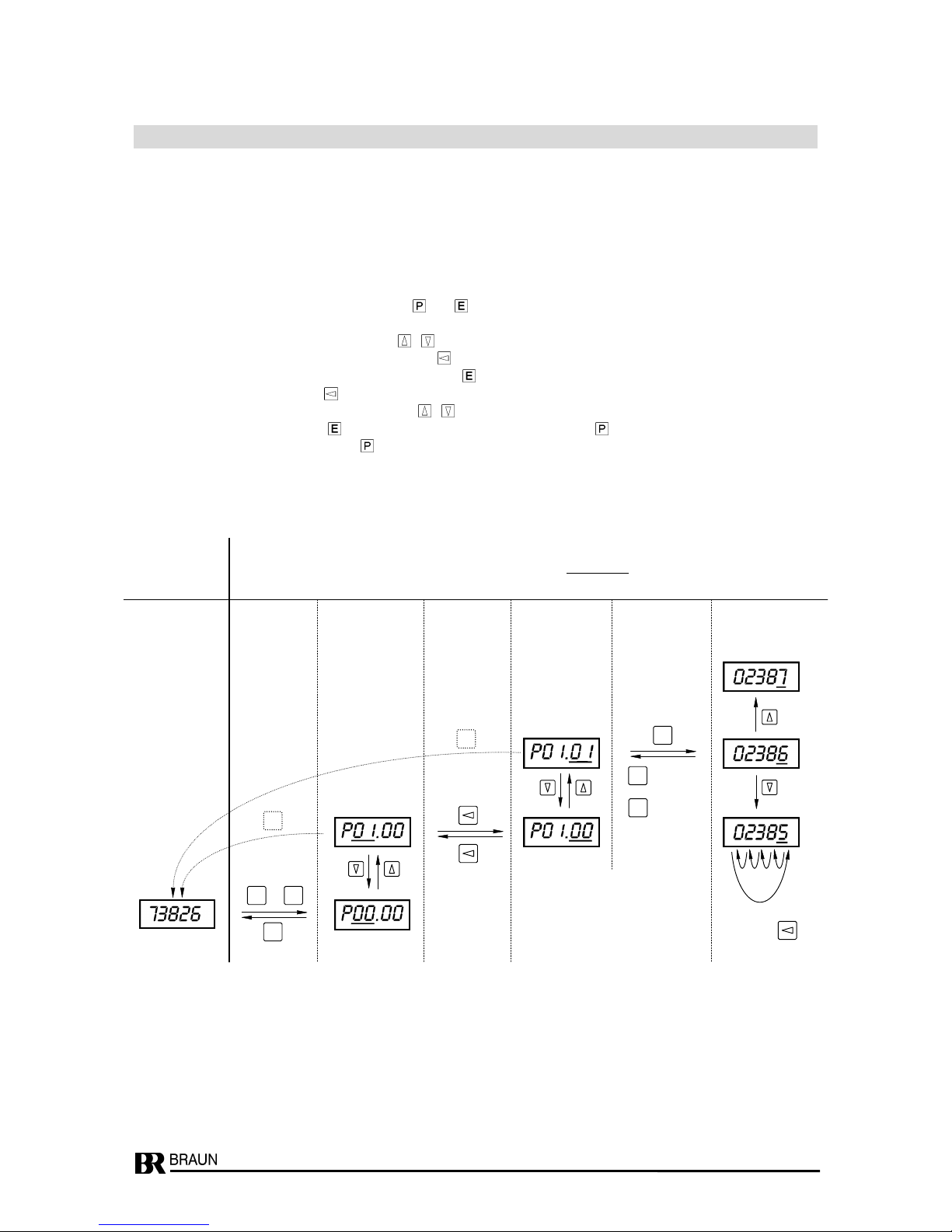
4.3 Setting the parameters via Front Keyboard
Principle:
Select a parameter via its ‚name’ Pgg.ss,
in that gg : Parameter-group number and
ss : Step-number within the group,
then display the value and alter if required.
Procedure:
Initiate programming phase by pressing keys and together;
instead of the normal display P00.00. appears
Select the group or step number with keys , .
Switch between Groups and Step Fields with the . key
Current value of the Parameters is displayed with key .
Select active position with the . key
Adjust the number in the active field with keys , .
Acknowledge and set with key , Discard (original value remains) with key .
Return to operational mode with the key.
See example below: Change parameter P01.01 from 2386 to 2387 or 2385.
Move
active
digit with
Normal Display while Programming
Display active digit(s) blinking (shown underlined here)
Select Select Change
Toggle Group Toggle Step-No. Toggle Parameter Value
with with with
key(s) Key Key
+
P P E E E
: Enter
or
: Cancel
P
Enter : new, changed value is valid
Cancel : original value still valid
P
P
 Loading...