

Page 1
Aesculap Power Systems
Acculan® 3Ti
Instructions for use/Technical description
Acculan® 3Ti attachments
Gebrauchsanweisung/Technische Beschreibung
Acculan® 3Ti Aufsätze
Mode d’emploi/Description technique
Acculan® 3Ti embouts
Instrucciones de manejo/Descripción técnica
Acculan® 3Ti cabezales
Istruzioni per l’uso/Descrizione tecnica
Acculan® 3Ti terminali
Instruções de utilização/Descrição técnica
Acculan® 3Ti cabeçotes
Gebruiksaanwijzing/Technische beschrijving
Acculan® 3Ti opzetstukken
Brugsanvisning/Teknisk beskrivelse
Acculan® 3Ti tilbehør
Bruksanvisning/Teknisk beskrivning
Acculan® 3Ti tillsatserna
Инструкция по примению/Техническое
описание
Acculan® 3Ti соединительные насадки
Page 2

Page 3
1
5.1
5
44.1
2.1
3
2
66.1
4.2
4.3
7.1
77.2
Page 4
Aesculap Power Systems
Acculan® 3Ti attachments
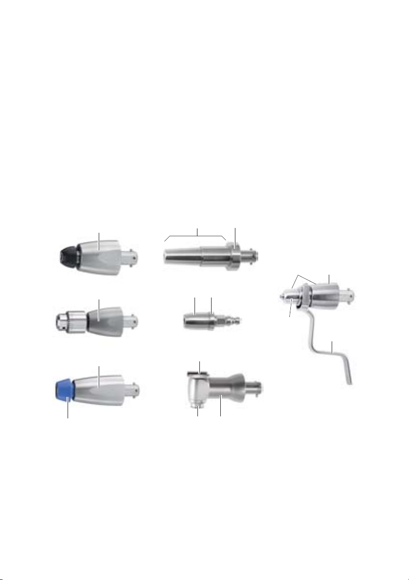
Legend
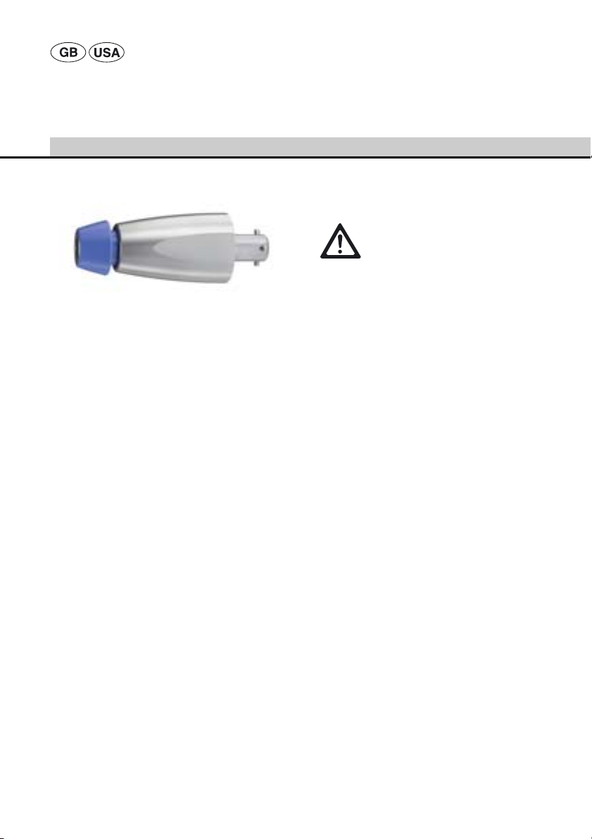
1 Drill attachment (black unlocking sleeve)
2 Reamer attachment (blue unlocking sleeve)
2.1 Unlocking sleeve
3 Drill attachment with Jacobs chuck
4 Kirschner wire attachment
4.1 Scale
4.2 Adjustment sleeve
4.3 Clamping lever
5 Drill attachment (for radiolucent angle
transmission)
5.1 Adapter for radiolucent angle transmission
6 Adapter (AO large to DHS/DCS)
6.1 Unlocking sleeve
7 Sagittal saw attachment
7.1 Saw blade coupling
7.2 Button for saw blade release/fixation
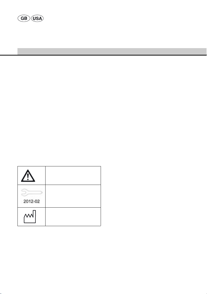
Symbols on product and packages
Adhere to instructions for use
Notice indicating the next scheduled service (date) by an international B. Braun/Aesculap agency,
see Maintenance
Date of manufacture
Contents
1. Safe handling ...........................................................3
2. Product description ................................................ 3
2.1 System components ............................................... 3
2.2 Components necessary for use ........................... 3
3. Drill and reamer attachments ............................. 4
3.1 Intended use .............................................................4
3.2 Operating principle ................................................. 4
3.3 Safe operation ......................................................... 4
Coupling a tool........................................................ 4
Uncoupling a tool................................................... 4
3.4 Technical specifications ........................................ 5
4. Kirschner wire attachment GB643R .................. 6
4.1 Intended use ............................................................. 6
4.2 Operating principle ................................................. 6
4.3 Safe operation ......................................................... 6
Inserting the Kirschner wire ................................ 7
Clamping the Kirschner wire............................... 7
4.4 Technical specifications ........................................ 7
5. Drill attachment GB645R (for radiolucent
angle transmission) ................................................8
5.1 Intended use ............................................................. 8
5.2 Operating principle ................................................. 8
5.3 Safe operation ......................................................... 8
Coupling the radiolucent transmission unit.... 8
Uncoupling the radiolucent transmission unit. 8
Coupling a tool........................................................ 9
Uncoupling a tool................................................... 9
5.4 Technical specifications ........................................ 9
6. Adapter GB628R (AO large to DHS/DCS) .......10
6.1 Intended use ...........................................................10
6.2 Operating principle ...............................................10
6.3 Safe operation .......................................................10
Coupling the adapter........................................... 10
Uncoupling the adapter...................................... 10
Coupling a tool...................................................... 10
Uncoupling a tool................................................. 10
6.4 Accessories .............................................................10
6.5 Technical specifications ......................................10
7. Sagittal saw attachment GB660R ...................11
7.1 Intended use ...........................................................11
7.2 Operating principle ...............................................11
7.3 Safe operation .......................................................11
Coupling the saw blade....................................... 11
Uncoupling the saw blade.................................. 11
7.4 Technical specifications ......................................11
8. Working with the attachments ........................12
8.1 System set-up ........................................................12
Connecting the accessories................................ 12
Coupling and uncoupling of attachments on
the drill and reamer motor unit........................ 12
2
Page 5
8.2 Function checks .....................................................13
8.3 General operation .................................................14
9. Validated processing procedure ........................14
9.1 General notes .........................................................15
9.2 Preparations at the place of use ......................15
9.3 Preparation prior to cleaning ............................15
9.4 Cleaning/Disinfecting ..........................................16
9.5 Manual cleaning/disinfecting ............................17
9.5 Manual cleaning and wipe disinfection ......... 17
9.6 Mechanical cleaning/disinfecting ....................18
Mechanical alkaline cleaning and thermal
disinfecting............................................................. 19
9.7 Inspection, maintenance and checks ..............20
9.8 Packaging ................................................................20
9.9 Sterilization method and parameters .............21
9.10 Sterilization for the US market .........................21
9.11 Storage .....................................................................21
10. Troubleshooting list ..............................................22
10.1 General malfunctions ..........................................22
10.2 Malfunctions of the Kirschner wire
attachment .............................................................23
10.3 Malfunctions of the sagittal saw
attachment .............................................................23
11. Maintenance ..........................................................24
12. Technical Service ...................................................24
13. Accessories/Spare parts .......................................25
14. Technical specifications ......................................26
14.1 Ambient conditions ..............................................26
15. Disposal ....................................................................26
16. Distributor in the US/Contact in Canada
for product information and complaints .......27
1. Safe handling
CAUTION
Federal law restricts this device to sale by or on
order of a physician!
¾ To prevent damage caused by improper setup or
operation and to avoid forfeiture of liability rights:
– Use the product only according to these
instructions for use.
– Observe all safety information and maintenance
advisories.
– Only combine Aesculap products with each other.
¾ Ensure that the product and its accessories are
operated and used only by persons with the
requisite training, knowledge or experience.
¾ Keep the instructions for use accessible for all O.R.
personnel.
¾ Always adhere to applicable standards.
2. Product description
2.1 System components
Designation Art. no. Enclosed
Cleaning
brush
Key for
Jacobs chuck
2.2 Components necessary for use
Designation Art. no.
Acculan® 3Ti small power
drill
Acculan® 3Ti drill and
reamer motor
Attachment Vary with indication
Adapter Vary with indication
Suitable tools and
Kirschner wires
Note
For possible combinations of attachments with the
Acculan® 3Ti small power drill GA671, follow the
information in Instructions for Use TA012033!
TA011944 All drill and reamer
attachments/Kirschner
wire attachment
GB643R
GA031201 For drill attachment
GA638R
GA671
GA672
Vary with indication
3
Page 6
Aesculap Power Systems
Acculan® 3Ti attachments
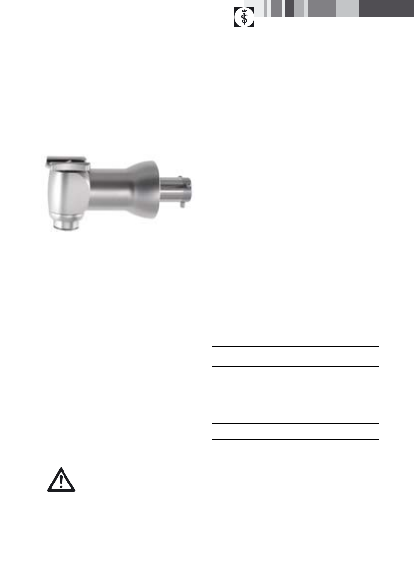
3. Drill and reamer attachments
Abb. 1
3.1 Intended use
Drill and reamer attachments are used to adapt
rotating tools applied in bone surgery for work on
bones and cartilage.
3.2 Operating principle
The drill and reamer attachments are powered by a
motor coupled through an Aesculap Acculan® 3Ti
coupling.
The drill and reamer attachments convert the motor
rotation to rotation of the tool adapted in the
respective attachment.
The drill and reamer attachments can be coupled to
the drive unit in three different angular positions at
steps of 120°.
Drill attachments are identified by their black
unlocking sleeves, whereas reamer attachments come
with blue unlocking sleeves.
3.3 Safe operation
Risk of injury due to heat necrosis!
¾ Do not use drill attachments to
operate reamer tools such as the
DANGER
Recommended application
Use GB630R, GB634R, GB635R, GB636R, GB637R and
GB638R only for drilling and tapping.
Use GB654R, GB655R and GB656R only for acetabular
reaming and medullary reaming.
¾ For information on how to connect the drill and
reamer attachments, siehe Coupling and uncoupling of attachments on the drill and reamer motor
unit.
Coupling a tool
¾ Slide back unlocking sleeve 2.1.
¾ Push the tool shaft in its proper position down to
the stop in the tool adapter of the attachment.
¾ Release unlocking sleeve 2.1.
The tool is now coupled.
Uncoupling a tool
¾ Slide back unlocking sleeve 2.1.
¾ Remove the tool.
acetabulum reamer and the
medullary reamer.
¾ Operate any reamer tool only
with a reamer attachment.
4
Page 7

3.4 Technical specifications
Drill attachments (black unlocking sleeve)
GB630R GB634R GB635R GB636R GB637R GB638R
Connection Hudson/
Zimmer
Dimensions
Length x ∅ in mm
Weight, in grams approx. 263 approx. 430 approx. 246 approx. 253 approx. 250 approx. 333
Gear
ratio
Drive speed, in
1/min
Torque
in Nm
Cannulation
∅ in mm
Reamer attachments (blue unlocking sleeve)
Connection Harris AO large Hudson/Zimmer
Dimensions
Length x ∅ in mm
Weight, in grams approx. 323 approx. 334 approx. 344
Gear ratio 100:1 100:1 100:1
Drive speed, in 1/min max. 250 max. 250 max. 250
Torque, in Nm max. 19 max. 19 max. 19
Cannulation ∅ in mm 444
approx.
100 x 39
25:1 25:1 25:1 25:1 25:1 25:1
max. 1 000 max. 1 000 max. 1 000 max. 1 000 max. 1 000 max. 1 000
max. 5 max. 5 max. 5 max. 5 max. 5 max. 5
4 4 4444
Jacobs chuck
keyless
∅ 0.6–7.4 mm
approx.
125 x 39
GB654R GB655R GB656R
approx. 106 x 39 approx. 107 x 39 approx. 118 x 39
AO small Aesculap
hexagon
approx.
90 x 39
approx.
86 x 39
Trinkle Jacobs chuck
with key
∅ 0–6.5 mm
approx.
93 x 39
approx.
110 x 39
5
Page 8
Aesculap Power Systems
Acculan® 3Ti attachments
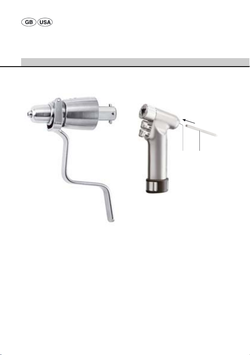
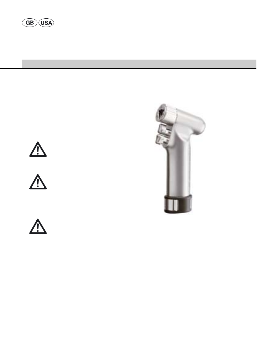
4. Kirschner wire attachment
GB643R
Abb. 2
4.1 Intended use
Kirschner wire (K-wire) attachments are used in
orthopedics and traumatology to insert Kirschner wires
into bones.
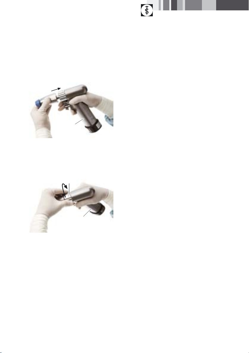
4.3 Safe operation
To protect against injuries when using long drilling
wires, screw in the Kirschner wire protection sleeve
supplied with the product.
17 15
Abb. 3
¾ Screw protection sleeve 15 into adapter 17.
¾ Connect the Kirschner wire attachment, siehe Cou-
pling and uncoupling of attachments on the drill
and reamer motor unit.
¾ Align clamping lever 4.3 over the trigger buttons of
the drill and reamer motor.
4.2 Operating principle
Kirschner wire attachments are powered by a motor
with an Aesculap Acculan® 3Ti coupling.
The Kirschner wire attachment is a quick-action chuck
that clamps and drives Kirschner wires.
6
Page 9

Inserting the Kirschner wire
The following diameter ranges can be set for the
adjustment sleeve:
∅ 0.6-1.8 mm
∅ 1.8-3.0 mm
∅ 3.0–4.0 mm
¾ Leave clamping lever 4.3 in forward position (away
from the drive unit).
¾ Set adjustment sleeve 4.2 to the correct diameter
range for the diameter of the Kirschner wire: Push
back and turn adjustment sleeve 4.2 until the
intended diameter range setting is reached.
¾ Release adjustment sleeve 4.2, making certain that
adjustment sleeve 4.2 clicks into position.
¾ Insert the Kirschner wire into the Kirschner wire
attachment until the required extension length is
reached.
The Kirschner wire is held in the intended position
in the attachment by an automatic clamping
mechanism.
Clamping the Kirschner wire
¾ Pull clamping lever 4.3 towards the motor unit (the
stronger the clamping lever is pulled, the stronger
the clamping force on the Kirschner wire).
The Kirschner wire is clamped in now.
Note
The Kirschner wire remains clamped only as long as the
clamping lever is pulled towards the motor unit. The
clamping lever automatically returns to its rest position
away from the motor unit, and the Kirschner wire can
be moved freely again as soon as the clamping lever is
released.
4.4 Technical specifications
GB643R
Kirschner wire ∅ in mm 0.6–4.0
Dimensions L x W x H, inmm93 x 36 x 137
Weight, in grams approx. 300
Gear ratio 25:1
Drive speed, in 1/min max. 1,000
7
Page 10
Aesculap Power Systems
Acculan® 3Ti attachments
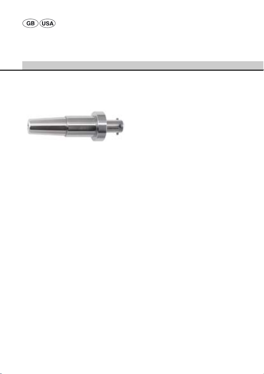
5. Drill attachment GB645R
(for radiolucent angle
transmission)
Abb. 4
Note
The drill attachment can be used only with Synthes
Radiolucent Drive 511.300!
Note
Always observe the instructions for use of Synthes
Radiolucent Drive 511.300!
5.1 Intended use
The drill attachment allows connecting a radiolucent
angle transmission for applying drill holes in the bone
under radiographic control.
5.2 Operating principle
The drill attachment is powered by a motor fitted with
an Aesculap Acculan® 3Ti coupling.
The drill attachment transfers the rotational speed of
the motor to the adapted radiolucent angle
transmission.
The drill attachment can be coupled to the motor unit
in three different positions, separated by 120°.
5.3 Safe operation
¾ Couple the drill attachment, siehe Coupling and
uncoupling of attachments on the drill and reamer
motor unit.
Coupling the radiolucent transmission unit
¾ Fully engage the radiolucent angle transmission in
adapter 5.1 of the drill attachment.
¾ If necessary, slightly move the radiolucent unit.
Uncoupling the radiolucent transmission unit
¾ Forcefully pull out the radiolucent angle
transmission from the drill attachment.
8
Page 11

Coupling a tool
Note
Always observe the instructions for use of Synthes
Radiolucent Drive 511.300!
Uncoupling a tool
Note
Always observe the instructions for use of Synthes
Radiolucent Drive 511.300!
5.4 Technical specifications
GB645R
Dimensions L x W x H, inmm110 x 35 x 35
Weight, in grams approx. 225
Gear ratio 30:1
Drive speed, in 1/min max. 900
9
Page 12
Aesculap Power Systems
Acculan® 3Ti attachments
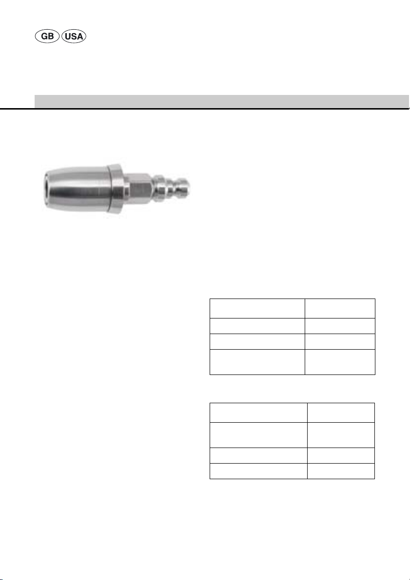
6. Adapter GB628R (AO large to
DHS/DCS)
Abb. 5
6.1 Intended use
The adapter is used for connecting tools with DHS/DCS
coupling to drill or reamer attachments with AOProtek coupling.
6.2 Operating principle
The adapter is driven by a drill or reamer attachment
powered by a motor fitted with an Aesculap Acculan®
3Ti coupling. The drill or reamer attachment transfers
the rotational speed of the motor to adapter GB628R
and thus to the coupled tool.
6.3 Safe operation
Note
Use the adapter only with Synthes tools with DHS/DCS
tool coupling or tools of a comparable geometry!
¾ For information on how to connect the drill and
reamer attachments, siehe Coupling and uncoupling of attachments on the drill and reamer motor
unit.
Uncoupling the adapter
¾ For uncoupling the adapter, siehe Uncoupling a
tool.
Coupling a tool
¾ Slide back unlocking sleeve 6.1.
¾ Insert the tool shaft in its correct position down to
the stop in the tool coupling of the adapter.
¾ Release unlocking sleeve 6.1.
The tool is now coupled.
Uncoupling a tool
¾ Slide back unlocking sleeve 6.1.
¾ Remove the tool.
6.4 Accessories
Designation Synthes art. no.
DHS Tripple Reamer 338.130, 338.430
DHS Reamer 357.044, 357.045
DHS Drill Bit 357.047, 351.270,
359.081, 359.079
6.5 Technical specifications
GB628R
Dimensions L x W x H, inmm61 x 22 x 22
Weight, in grams approx. 70
Drive speed, in 1/min max. 250
Coupling the adapter
¾ For coupling the adapter, siehe Coupling a tool.
10
Page 13
7. Sagittal saw attachment
GB660R
Abb. 6
7.1 Intended use
The sagittal saw attachment is used for intraoperative
dissection of bone and cartilage tissue.
7.2 Operating principle
The sagittal saw attachment is powered by a motor
fitted with the Aesculap Acculan® 3Ti coupling.
The sagittal saw attachment converts the motor
rotation into oscillation of the saw blade. The bone is
dissected by the oscillating movement of the saw
blade.
No key or wrench is required for inserting the saw
blades. The sagittal saw attachment can be coupled to
the drive unit in three different positions separated by
steps of 120°.
7.3 Safe operation
¾ Connect the sagittal saw attachment, siehe Cou-
pling and uncoupling of attachments on the drill
and reamer motor unit.
Coupling the saw blade
¾ Insert the saw blade with its coupling end in the
slot of saw blade coupling 7.1 as far as it will go.
Ensure that the locking pin engages in the saw
blade fenestration, and that the lateral stops of the
saw blade rest on the coupling.
¾ If necessary press button for saw blade release/fix-
ation 7.2.
¾ Check that the tool is seated properly: Pull at the
saw blade.
Uncoupling the saw blade
¾ Fully press button for saw blade release/
fixation 7.2.
¾ Extract the saw blade from saw blade coupling 7.1.
7.4 Technical specifications
GB660R
Dimensions L x W x H, inmm89 x 36 x 44
Weight, in grams approx. 270
Gear ratio 1.5:1
Stroke frequency in 1/min max. 17 000
WARNING
Risk of injury caused by inadvertent
loosening of the saw blade during
operation!
¾ Do not press the button for saw
blade release/fixation during
operation.
¾ Check for secure fixation of the
tool after any tool change.
11
Page 14
Aesculap Power Systems
Acculan® 3Ti attachments
8. Working with the
attachments
8.1 System set-up
Note
The attachments are supplied in unsterile condition.
Risk of infection and
contamination!
¾ Sterilize the attachments prior
DANGER
WARNING
CAUTION
Connecting the accessories
Combinations of accessories that are not mentioned in
the present instructions for use may only be employed
if they are specifically intended for the respective
application, and if they do not compromise the
performance and safety characteristics of the
products.
¾ Please address any questions in this respect to your
B. Braun/Aesculap partner or to Aesculap Customer
Service.
to operation.
Risk of injury due to inadvertent
activation of the motor during
coupling of an attachment/tool!
¾ Secure motors that are not
actually used against
inadvertent activation.
Damage to the attachment caused
by inappropriate tool!
¾ Use an appropriate tool for
changing the attachment tool.
Avoid contact with cutting
edges.
Coupling and uncoupling of attachments on
the drill and reamer motor unit
Protection against inadvertent activation
Abb. 7
The rotational speed control button can be locked to
prevent inadvertent activation of the drill and reamer
motor unit during a tool change.
Note
For further information on the drill and reamer motor
unit, see TA011869.
12
Page 15
Coupling
A
Abb. 8
¾ Push the attachment onto drill and reamer motor
A until it clicks into position.
Uncoupling
B
A
Abb. 9
¾ Turn rotating sleeve B in the direction of the arrow
(clockwise when viewed from the rear end of drill
and reamer motor unit A).
¾ Remove the attachment from drill and reamer
motor unit A.
8.2 Function checks
Note
Function checks must be performed prior to each
operation with the unit and after each intraoperative
attachment or tool change!
¾ Make certain that the attachment is securely
seated.
¾ Make certain that the tool/Kirschner wire is seated
properly.
¾ Briefly run the drill and reamer motor unit, with the
attachment coupled and a tool inserted, at
maximum speed in clockwise and
counterclockwise mode.
¾ Watch out for damage, irregular running noises,
excessive vibrations and excessive heat developed
by the handpieces.
¾ Only use the unit if it is in perfect condition.
13
Page 16
Aesculap Power Systems
Acculan® 3Ti attachments
8.3 General operation
Risk of injury caused by
aerosol formation or particles
during reaming, cutting or
WARNING
WARNING
¾ Start the motor powering the attachment at
moderate speed.
¾ To avoid slipping, apply only moderate pressure.
¾ To avoid tool breakage, do not bend the tool.
¾ Cool the tool during operation. This will improve
chip removal and reduce the risk of necrosis.
drilling!
¾ Always wear eye
protection when using the
drill and reamer motor
unit.
Risk of burns to skin and
tissue caused by hot, blunt
tools!
¾ Do not use damaged or
defective tools.
9. Validated processing procedure
Note
Adhere to national statutory regulations, international
standards and guidelines, and local, clinical hygiene
instructions for sterile processing.
Note
For patients with Creutzfeldt-Jakob disease (CJD),
suspected CJD or possible variants of CJD, observe the
relevant national regulations concerning the
reprocessing of the products.
Note
Mechanical processing should be preferred over
manual cleaning, as mechanical processing produces
better and more reliable cleaning results.
Note
Up-to-date information on processing can be found on
the Aesculap Extranet at www.aesculap-extra.net
Note
Successful processing of this medical product can only
be ensured if processing is performed through a
validated processing procedure. The user/processor is
responsible for the validation.
Due to process tolerances, the manufacturer’s
specifications can only serve as an approximate guide
for assessing the processing procedures applied by the
individual operator/processors.
14
Page 17

9.1 General notes
Encrusted or fixated residues from surgery can make
the cleaning process more difficult or ineffective, and
can cause corrosion of stainless steels. To avoid this,
the time interval between application and processing
should not exceed 6 h, and neither fixating precleaning temperatures >45 °C nor any fixating
disinfecting agents (active ingredient: aldehyde,
alcohol) be used.
Excessive doses of neutralizers or basic detergents can
cause chemical degradation and/or fading and
obliteration of laser inscriptions on stainless steel
surfaces, regarding visual reading and machinereadability of the inscriptions.
Residues containing chlorine or chlorides e.g. in
surgical residues, medicines, saline solutions and in the
service water used for cleaning, disinfection and
sterilization will cause corrosion damage (pitting,
stress corrosion) and result in the destruction of
stainless steel products. To remove such residues, the
products must be rinsed sufficiently with fully
desalinated water and dried thoroughly.
Only process chemicals that have been tested and
approved (e.g. VAH/DGHM or FDA approval or CE mark)
and which are compatible with the product’s materials
according to the chemical manufacturers’
recommendations may be used for processing the
product. All process parameters specified by the
chemical’s manufacturer, such as temperatures,
concentrations and exposure times, must be strictly
observed. Failure to do so can result in the following
problems:
• optical changes to the material, e.g. fading or
discoloration of titanium or aluminum. For
aluminum, pH >8 in the application/process can
already cause visible surface changes.
• material damage such as corrosion, cracks,
fracturing, premature aging or swelling.
¾ Do not use process chemicals that cause stress
cracking or brittleness of plastic materials.
¾ Further detailed advice on hygienically safe and
material-/value-preserving reprocessing can be
found at www.a-k-i.org, Publications Red Brochure
– Proper maintenance of instruments.
9.2 Preparations at the place of use
¾ Disassemble the product immediately after use, as
described in the respective instructions for use.
¾ Dismount all coupled components, e.g. tools (drills,
saw blades, etc.), accessories (adapters, protection
sleeves, etc.), tubes, cables, batteries, etc.
¾ Remove visible surgical residues as completely as
possible, using a lint-free wet wipe.
9.3 Preparation prior to cleaning
¾ Have the product dry in a disposal container and
ready for immediate cleaning and disinfecting
within 30 min after use.
15
Page 18

Aesculap Power Systems
Acculan® 3Ti attachments
9.4 Cleaning/Disinfecting
Damage to the product due to
inappropriate cleaning/disinfecting
agents and/or excessive
CAUTION
temperatures!
¾ Use cleaning and disinfecting
agents according to the
manufacturer’s instructions.
Cleaning and disinfecting agents
must
- be approved for plastics and
high-grade steel,
- not attack softeners (e.g.
silicone).
¾ Observe specifications regarding
concentration, temperature and
exposure time.
¾ Do not exceed the maximum
allowable cleaning temperature
of 55 °C.
¾ Do not clean the motors/handpieces in an
ultrasound bath and do not immerse them in any
fluid.
Let any fluid that penetrates into the product drain
out immediately to avoid the risk of corrosion/
malfunctioning of the product.
16
Page 19

9.5 Manual cleaning/disinfecting
Manual cleaning and wipe disinfection
Stage Step T
[°C/°F]t[min]
I Cleaning RT
(cold)
II Drying RT - - - -
III Wipe disinfection - ≥1 - - Meliseptol HBV wipes
IV Final rinse RT
(cold)
V Drying RT - - - -
D–W: Drinking water
FD–W: Fully desalinated water (demineralized)
RT: Room Temperature
Stage I
¾ Clean the product under running tap water, using
a suitable cleaning brush if necessary, until all
visible residues have been removed from the
surfaces.
¾ Mobilize non-rigid components, such as set screws,
links, etc. during cleaning.
¾ Make certain the product is positioned in such a
way that water will not enter the product e.g.
through coupling interfaces. (Immediately remove
any fluid that entered inadvertently.)
¾ Use the special cleaning brush (TA011944) for
cleaning the cannulation of drill and reamer
attachments/Kirschner wire attachment GB643R.
¾ To avoid the risk of corrosion, do not use a metal
brush or other abrasives that would damage the
surfaces for cleaning the product.
¾ Clean difficult-to-access areas with soft round
plastic brushes of fitting diameter.
Conc.
[%]
--D–W-
0.5 - FD–W -
Stage II
¾ Dry the product with lint-free tissue or medical-
Stage III
¾ Wipe all surfaces of the product with a single-use
Stage IV
¾ After the specified exposure time (of at least
¾ Hold the product in such a way that water cannot
¾ Allow water to drip off for a sufficient length of
Water
quality
50 % Propan-1-ol
quality filtered compressed air.
disinfecting wipe.
1 minute), rinse the disinfected surfaces under
running FD water.
enter it e.g. through couplings or adapters.
time.
Chemical
17
Page 20

Aesculap Power Systems
Acculan® 3Ti attachments
Stage V
¾ Dry the product with lint-free tissue or medical-
quality filtered compressed air.
9.6 Mechanical cleaning/disinfecting
Note
The disinfector must be of proven effectiveness (e.g.
DGHM or FDA approval or CE mark).
Note
For thermal disinfection, always use fully desalinated
(demineralized) water. Ensure that Ao is >3 000 for the
process.
Note
The disinfector used for processing must be serviced
and checked at regular intervals.
¾ If the washer/disinfector is not fitted with internal
rinsing, carry out manual precleaning of the
cannulation, see Manual cleaning/disinfecting,
Stage I.
¾ For Kirschner wire attachment GB643R: Set
adjustment sleeve 4.2 to the largest Kirschner wire
diameter.
¾ For sagittal saw attachment GB660R: Do not rinse
through the interior of the sagittal saw
attachment. Do not connect the Eccos® holder of
the sagittal saw attachment to the rinsing
connector of the washer/disinfector.
¾ Use the Eccos® tray fitted with Acculan® 3Ti
holders, or mount appropriate holders in a suitable
tray (instructions for use TA009721 for Aesculap
Eccos® holder system).
¾ Insert the product in its proper position in the
Eccos® holder.
¾ Connect the internal rinsing equipment at the
Eccos® holder and at the special connector of the
rinsing cart.
18
Page 21

Mechanical alkaline cleaning and thermal disinfecting
Machine type: Single-chamber washer/disinfector without ultrasound
Stage Step T
[°C/°F]
I Prerinse <25/77 3 D–W -
II Cleaning 55/131 10 FD–W BBRAUN HELIMATIC CLEANER
III Intermediate rinse >10/50 1 FD–W -
IV Thermal disinfecting 90/194 5 FD–W -
V Drying - - - according to disinfecting
D–W: Drinking water
FD–W: Fully desalinated water (demineralized)
t
[min]
Water
quality
Chemical/Note
alkaline with tensides,
application solution 0.5 %
program
19
Page 22
Aesculap Power Systems
Acculan® 3Ti attachments
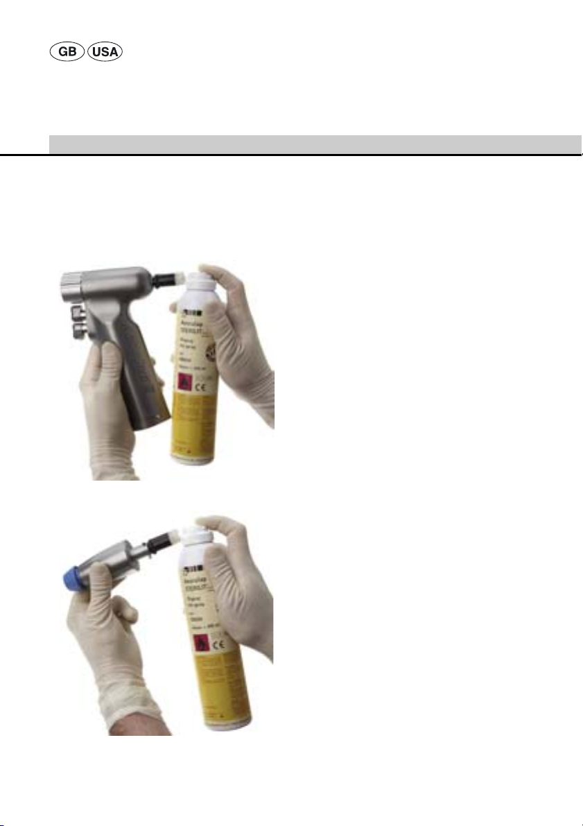
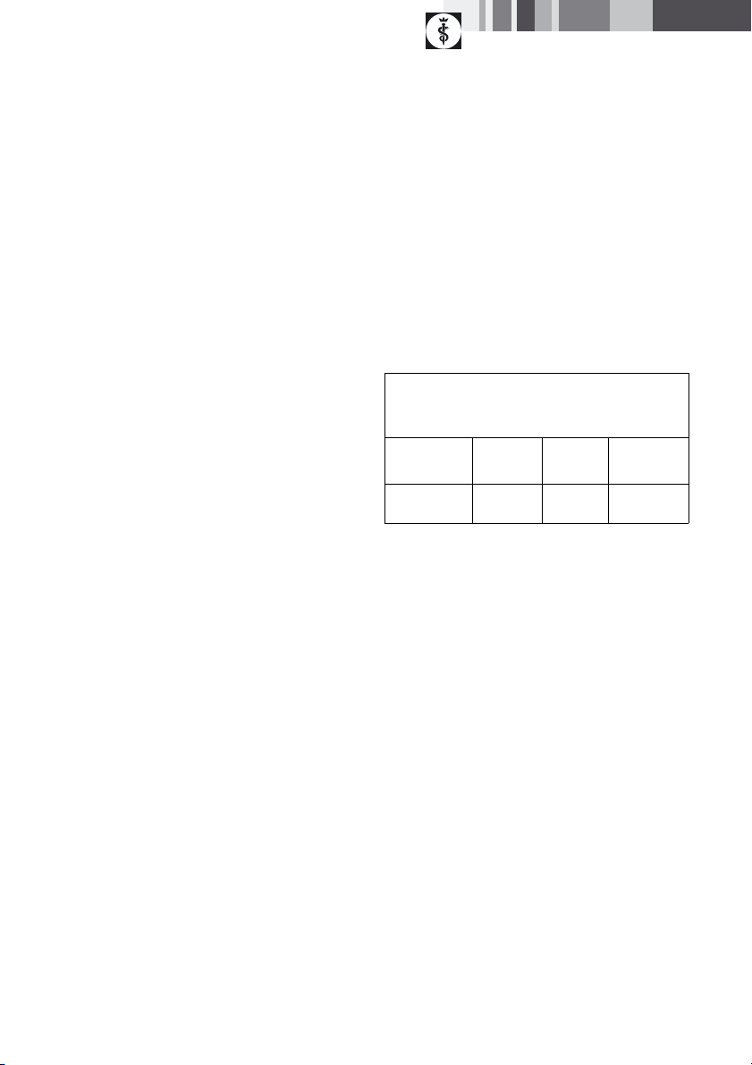
9.7 Inspection, maintenance and checks
Note
Aesculap recommends occasional spraying of moving
parts, e.g. triggers, couplings, cover lids, etc. with
Aesculap STERILIT® Power Systems Oil Spray GB600!
Fig. 10
¾ Allow the product to cool down to room
temperature.
¾ Inspect the product after each cleaning and
disinfecting cycle to be sure it is clean, functional
and undamaged.
¾ Mount the STERILIT® Power Systems adapter
supplied with the product on Aesculap STERILIT®
Power Systems Oil Spray and spray into the
cannulation of the small power drill, see Fig. 10,
and through the drill, reamer and Kirschner wire
attachments, see Fig. 11, in each case from the rear
end and for about 1 sec.
¾ After cleaning/disinfecting, inspect all surfaces and
difficult to access spots on the product for visible
dirt or debris.
¾ Check the product for any damage, atypical
running noise, overheating or excessive vibration.
¾ Inspect tools for broken, damaged or blunt edges.
¾ Set aside the product if it is damaged.
9.8 Packaging
¾ Follow the instructions for use of the respective
packaging and storage holders (e.g. instructions for
use TA009721 for the Aesculap Eccos® holder
system).
¾ Insert the product in its proper position in the
Eccos® holder, or p ut it on a tray in such a way that
the product is protected against damage. Make
certain that all cutting edges are protected.
¾ Package trays appropriately for the sterilization
process (e.g. in Aesculap sterile containers).
¾ Pack the product in such a way that the packaging
will prevent recontamination of the product
(DIN EN ISO 11607).
Fig. 11
20
Page 23
9.9 Sterilization method and
parameters
Note
The product may only be sterilized with all tools etc.
unmounted.
¾ Make certain that all external and internal surfaces
of the product will be exposed to the sterilizing
agent.
¾ Validated sterilization process
– Disassemble the product
– Steam sterilization through fractionated vacuum
process
– Steam sterilizer according to DIN EN 285 and
validated according to DIN EN ISO 17665
– Sterilization through fractionated vacuum process
at 134 °C/2 bar; holding time 5 min.
¾ When sterilizing several products at the same time
in one steam sterilizer: Make certain that the
maximum allowable load capacity of the steam
sterilizer, as specified by the manufacturer, is not
exceeded.
9.10 Sterilization for the US market
• Aesculap does not recommend the device sterilized
by flash or chemical sterilization.
• Sterilization may be accomplished by steam autoclave in a standard prevacuum cycle.
To achieve a sterility assurance level of 10
recommends the following parameters:
Aesculap Orga Tray/Sterilcontainer (perforated
bottom)
Minimum cycle parameters*
Sterilization
method
Pre-vacuum 270 °F—
*Aesculap has validated the above sterilization cycle
and has the data on file. The validation was accomplished in an Aesculap Sterilcontainer cleared by FDA
for the sterilization and storage of these instruments.
Other sterilization cycles may also be suitable, however individuals or hospitals not using the recommended method are advised to validate any alternative
method using appropriate laboratory techniques. Use
an FDA cleared accessory to maintain sterility after
processing, such as a wrap, pouch, etc.
Temp. Time Minimum
4 min 20 min
275 °F
-6
, Aesculap
drying time
9.11 Storage
¾ Store sterile products in germ-proof packaging
under dust protection in a dry, dark and
temperature-controlled room.
21
Page 24

Aesculap Power Systems
Acculan® 3Ti attachments
10. Troubleshooting list
10.1 General malfunctions
Malfunction Cause Finding Remedy
Loud noise Defective gearing Loud noise Have product repaired by the
manufacturer
Tool not moving Attachment not coupled
properly
Defective gearing Motor drive not turning;
- - see TA011869
Deficient cutting
performance
Tool cannot be
coupled
Blunt tool Tool overheats Use a new tool
Wrong tool Incompatible tool Insert appropriate tool
Debris Debris on tool or in
Deformation Deformed tools/coupling
Attachment can not be
extracted from the motor
unit
blocked
Motor running, but not
driving the saw
coupling
components
Couple the attachment
correctly, see Coupling and
uncoupling of attachments on
the drill and reamer motor
unit
Have product repaired by the
manufacturer
Have product repaired by the
manufacturer
Clean the tool/coupling
Have product repaired by the
manufacturer
22
Page 25

10.2 Malfunctions of the Kirschner wire attachment
Malfunction Cause Finding Remedy
Kirschner wire cannot
be inserted into
Kirschner wire
attachment
Kirschner wire not
turning
Incorrect adjustment of
Kirschner wire
attachment
Incorrect adjustment of
Kirschner wire
attachment
Clamping lever open Clamping lever open Close the clamping lever
Kirschner wire diameter
not matching the
setting of the adjustment
sleeve
Kirschner wire diameter
not matching the
setting on the
adjustment scale
Set the adjustment sleeve to
the correct Kirschner wire
diameter
Set the adjustment sleeve to
the correct Kirschner wire
diameter
10.3 Malfunctions of the sagittal saw attachment
Malfunction Cause Finding Remedy
Saw blade cannot be
uncoupled
Release button not
pressed through
properly
Locking pin not fully
releasing the saw blade
Fully press down the release
button, see Coupling the saw
blade
23
Page 26
Aesculap Power Systems
Acculan® 3Ti attachments
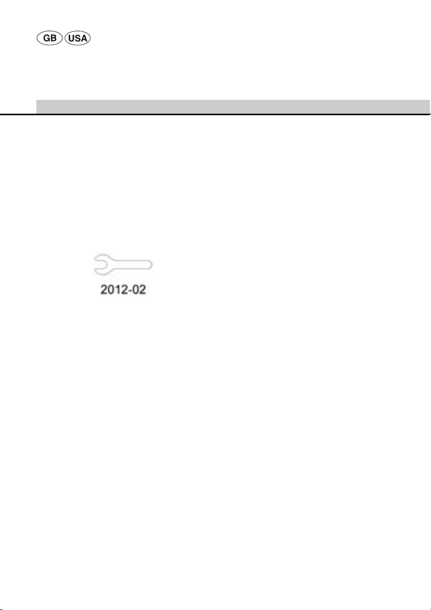
11. Maintenance
To ensure reliable operation, maintenance has to be
carried out as indicated on the service label, see Fig. 12,
e.g. February 2012.
Such maintenance must also include a safety
inspection according to §6 MPBetreibV (or equivalent).
The extent of the safety inspection is specified in the
Service Manual, which is available as a separate
document.
For services to this end, please contact your national B.
Braun/Aesculap agency, see Technical Service.
Fig. 12
12. Technical Service
For service and repairs, please contact your national
B. Braun/Aesculap agency.
Modifications carried out on medical technical
equipment may result in loss of guarantee/warranty
rights and forfeiture of applicable licenses.
Service addresses
Aesculap Technischer Service
Am Aesculap-Platz
78532 Tuttlingen / Germany
Phone: +49 7461 95-1601
Fax: +49 7461 14-939
E-Mail: ats@aesculap.de
Or in the US:
Aesculap Inc.
Attn. Aesculap Technical Services
615 Lambert Pointe Drive
Hazelwood, MO 63042
Aesculap Repair Hotline
Phone: +1 800 214-3392
Fax: +1 314 895-4420
Other service addresses can be obtained from the
address indicated above.
24
Page 27

13. Accessories/Spare parts
Designation Application Art. no.
Cleaning brush All drill and reamer attachments/Kirschner wire
Key for Jacobs chuck attachments Only for drill attachment GB638R GA031201
Eccos® holder, triple All attachments GB496R
Eccos® holder, single All attachments GB497R
Aesculap STERILIT® Power
Systems oil spray
STERILIT® Power Systems adapter All drill, reamer and Kirschner wire attachments GB600840
Eccos® tray with holders for
Acculan® 3Ti
Note
For further information about the Aesculap Eccos® holder system, see TA009721.
attachment GB643R
Only for Kirschner wire attachment GB644R TA011327
All attachments GB600
All attachments GB243R
TA011944
GB244R
25
Page 28
Aesculap Power Systems
Acculan® 3Ti attachments
14. Technical specifications
Classification acc. to Directive 93/42/EEC
Art. no. Designation Class
GB628R Adapter IIa
GB630R Drill attachment Hudson/Zimmer IIa
GB634R Jacobs chuck, keyless IIa
GB635R Drill attachment AO small IIa
GB636R Drill attachment Aesculap
hexagon
GB637R Drill attachment Trinkle IIa
GB638R Drill attachment Jacobs chuck
with key
GB643R Kirschner wire attachment IIa
GB645R Drill attachment for radiolucent
angle transmission
GB654R Reamer attachment Harris IIa
GB655R Reamer attachment A0 large IIa
GB656R Reamer attachment Hudson/
Zimmer
GB660R Sagittal saw attachment IIa
IIa
IIa
IIa
IIa
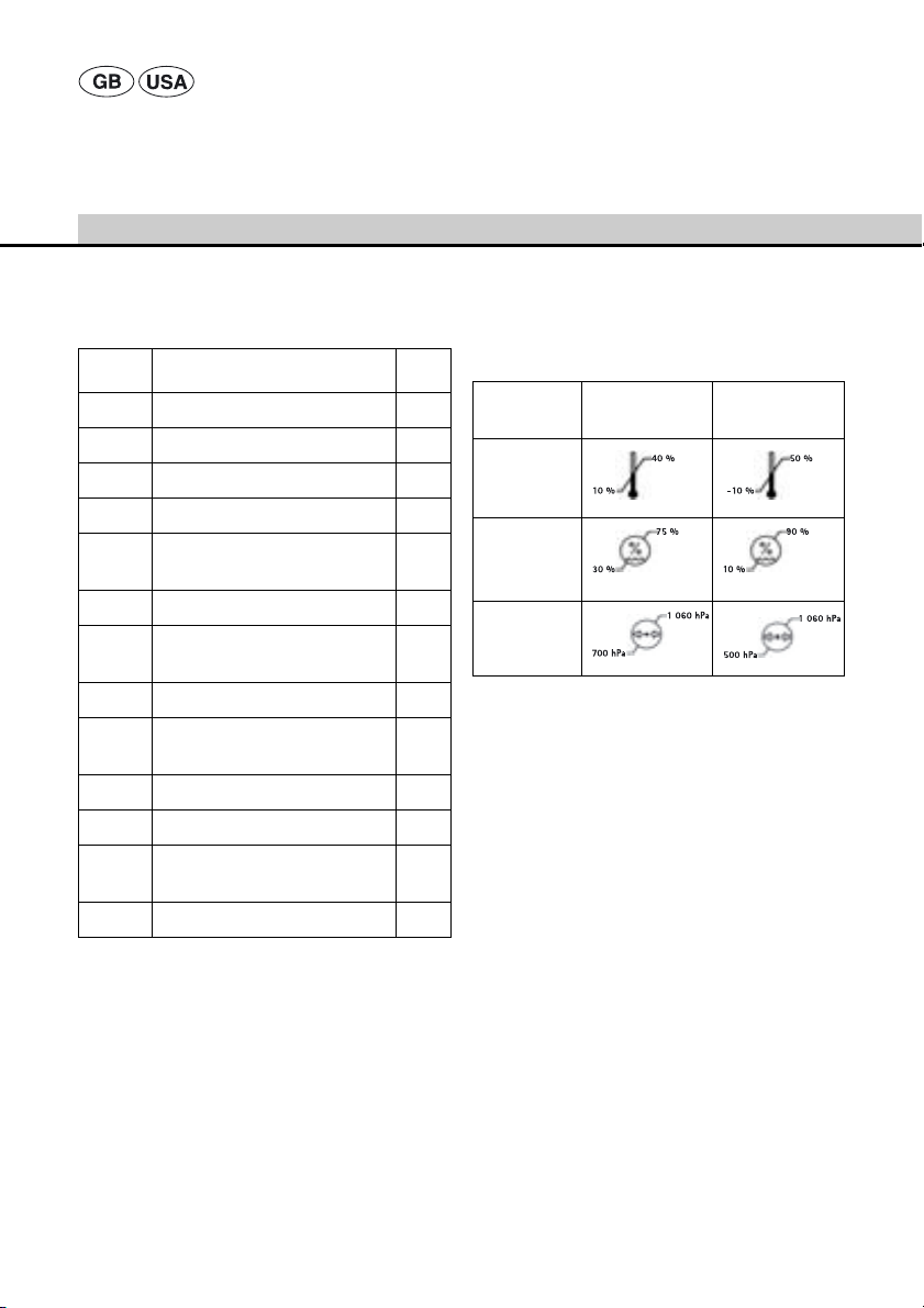
14.1 Ambient conditions
Operation Transport and
storage
Temperature
Relative
humidity
Atmospheric
pressure
26
Page 29
15. Disposal
Note
The user institution is obliged to process the product
before its disposal, see Validated processing procedure.
Adhere to national regulations
when disposing of or recycling the
product, its components and its
packaging!
The recycling pass can be
downloaded from the Extranet as a
PDF document under the respective
article number. (The recycling pass
includes disassembling instructions
for the product, as well as
information for proper disposal of
components harmful to the
environment.)
Products carrying this symbol are
subject to separate collection of
electric and electronic devices.
Within the European Union, disposal
is taken care of by the manufacturer
as a free-of-charge service.
¾ Please contact your national B. Braun/Aesculap
agency with any inquiries regarding the disposal of
the product, see Technical Service
16. Distributor in the US/Contact
in Canada for product information and complaints
Aesculap Inc.
3773 Corporate Parkway
Center Valley, PA 18034
USA
27
Page 30
Aesculap Power Systems
Acculan® 3Ti Aufsätze
Legende
1 Bohraufsatz (schwarze Entriegelungshülse)
2 Fräsaufsatz (blaue Entriegelungshülse)
2.1 Entriegelungshülse
3 Bohraufsatz mit Dreibackenfutter
4 Spickdrahtfutter
4.1 Skala
4.2 Einstellhülse
4.3 Spannhebel
5 Bohraufsatz (für röntgenstrahldurchlässiges
Winkelgetriebe)
5.1 Aufnahme für röntgenstrahldurchlässiges
Winkelgetriebe
6 Adapter (AO groß auf DHS/DCS)
6.1 Entriegelungshülse
7 Sagittalsägeaufsatz
7.1 Sägeblattkupplung
7.2 Druckknopf zur Sägeblattentriegelung/-fixierung
Symbole an Produkt und Verpackung
Gebrauchsanweisung einhalten
Hinweis auf den nächsten
Instandhaltungstermin (Datum)
bei der internationalen B. Braun/
Aesculap-Vertretung, siehe
Instandhaltung
Herstelldatum
Inhaltsverzeichnis
1. Sichere Handhabung ............................................29
2. Gerätebeschreibung .............................................29
2.1 Lieferumfang ..........................................................29
2.2 Zum Betrieb erforderliche Komponenten ......29
3. Bohr- und Fräsaufsätze .......................................30
3.1 Verwendungszweck ..............................................30
3.2 Funktionsweise ......................................................30
3.3 Bedienung ...............................................................30
Werkzeug kuppeln................................................ 30
Werkzeug entkuppeln.......................................... 30
3.4 Technische Daten ..................................................31
4. Spickdrahtfutter GB643R ...................................32
4.1 Verwendungszweck ..............................................32
4.2 Funktionsweise ......................................................32
4.3 Bedienung ...............................................................32
Spickdraht einführen ........................................... 33
Spickdraht spannen.............................................. 33
4.4 Technische Daten ..................................................33
5. Bohraufsatz GB645R (für röntgenstrahldurch-
lässiges Winkelgetriebe) .....................................34
5.1 Verwendungszweck ..............................................34
5.2 Funktionsweise ......................................................34
5.3 Bedienung ...............................................................34
Röntgenstrahldurchlässiges Winkelgetriebe
kuppeln .................................................................... 34
Röntgenstrahldurchlässiges Winkelgetriebe
entkuppeln.............................................................. 34
Werkzeug kuppeln................................................ 35
Werkzeug entkuppeln.......................................... 35
5.4 Technische Daten ..................................................35
6. Adapter GB628R (AO groß auf DHS/DCS) .....36
6.1 Verwendungszweck ..............................................36
6.2 Funktionsweise ......................................................36
6.3 Bedienung ...............................................................36
Adapter kuppeln.................................................... 36
Adapter entkuppeln.............................................. 36
Werkzeug kuppeln................................................ 36
Werkzeug entkuppeln.......................................... 36
6.4 Zubehör ....................................................................36
6.5 Technische Daten ..................................................36
7. Sagittalsägeaufsatz GB660R .............................37
7.1 Verwendungszweck ..............................................37
7.2 Funktionsweise ......................................................37
7.3 Bedienung ...............................................................37
Sägeblatt kuppeln................................................. 37
Sägeblatt entkuppeln........................................... 37
7.4 Technische Daten ..................................................37
8. Arbeiten mit den Aufsätzen ...............................38
28
Page 31

8.1 Bereitstellen ...........................................................38
Zubehör anschließen............................................ 38
Aufsätze an Bohr- und Fräsantrieb kuppeln
und entkuppeln...................................................... 38
8.2 Funktionsprüfung ..................................................39
8.3 Allgemeine Bedienung .........................................40
9. Validiertes Aufbereitungsverfahren .................40
9.1 Allgemeine Hinweise ...........................................41
9.2 Vorbereitung am Gebrauchsort .........................41
9.3 Vorbereitung vor der Reinigung .......................41
9.4 Reinigung/Desinfektion .......................................42
9.5 Manuelle Reinigung/Desinfektion ....................43
Manuelle Reinigung und
Wischdesinfektion................................................. 43
9.6 Maschinelle Reinigung/Desinfektion ...............44
Maschinelle alkalische Reinigung und
thermische Desinfektion..................................... 45
9.7 Kontrolle, Wartung und Prüfung ......................46
9.8 Verpackung .............................................................46
9.9 Sterilisieren .............................................................47
9.10 Lagerung ..................................................................47
10. Fehler erkennen und beheben ...........................48
10.1 Allgemeine Störungen .........................................48
10.2 Störungen am Spickdrahtfutter ........................49
10.3 Störungen am Sagittalsägeaufsatz ..................49
11. Instandhaltung ......................................................49
12. Technischer Service ..............................................50
13. Zubehör/Ersatzteile ..............................................50
14. Allgemeine Technische Daten ...........................51
14.1 Umgebungsbedingungen ....................................51
15. Entsorgung ..............................................................51
1. Sichere Handhabung
¾ Um Schäden durch unsachgemäßen Aufbau oder
Betrieb zu vermeiden und Haftung nicht zu gefährden:
– Produkt nur gemäß dieser Gebrauchsanweisung
verwenden.
– Sicherheitsinformationen und Instandhaltungs-
hinweise einhalten.
– Nur Aesculap-Produkte miteinander kombinieren.
¾ Produkt und Zubehör nur von Personen betreiben
und anwenden lassen, die die erforderliche Ausbildung, Kenntnis oder Erfahrung haben.
¾ Gebrauchsanweisung für das OP-Personal zugäng-
lich aufbewahren.
¾ Gültige Normen einhalten.
2. Gerätebeschreibung
2.1 Lieferumfang
Bezeichnung Art.-Nr. Beiliegend
Reinigungsbürste TA011944 Alle Bohr- und
Schlüssel für
Dreibackenfutter
GA031201 Bei Bohraufsatz
2.2 Zum Betrieb erforderliche Komponenten
Bezeichnung Art.-Nr.
Acculan® 3Ti Kleine Bohrmaschine
Acculan® 3Ti Bohr- und Fräsantrieb
Aufsatz Je nach Indikation
Adapter Je nach Indikation
geeignete Werkzeuge und
Spickdrähte
Hinweis
Für Kombinationsmöglichkeiten der Aufsätze auf die
Acculan® 3Ti Kleine Bohrmaschine GA671, Gebrauchsanweisung einhalten, siehe TA012033 !
Fräsaufsätze/
Spickdrahtfutter GB643R
GB638R
GA671
GA672
Je nach Indikation
29
Page 32

Aesculap Power Systems
Acculan® 3Ti Aufsätze
3. Bohr- und Fräsaufsätze
Abb. 1
3.1 Verwendungszweck
Bohr- und Fräsaufsätze nehmen rotierende Werkzeuge
auf, die in der Knochenchirurgie eingesetzt werden, um
Knochen und Knorpel zu bearbeiten.
3.2 Funktionsweise
Die Bohr- und Fräsaufsätze werden durch einen
Antrieb mit Aesculap Acculan® 3Ti Kupplung angetrieben.
Die Bohr- und Fräsaufsätze nehmen die Drehzahl des
Antriebs auf und übertragen die Rotation auf das im
jeweiligen Aufsatz eingespannte Werkzeug.
Die Bohr- und Fräsaufsätze können in drei verschiedene Stellungen, um je 120° versetzt, auf den Antrieb
gekuppelt werden.
Bohraufsätze sind an der schwarzen und Fräsaufsätze
an der blauen Entriegelungshülse erkennbar.
3.3 Bedienung
Verletzungsgefahr durch Hitzenekrosenbildung!
¾ Bohraufsätze nicht zum Betrieb
GEFAHR
Empfohlene Anwendung
GB630R, GB634R, GB635R, GB636R, GB637R und
GB638R nur zum Bohren und Gewindeschneiden verwenden.
GB654R, GB655R und GB656R nur zum Fräsen und
Markraumbohren verwenden.
¾ Bohr- und Fräsaufsätze anschließen, siehe Auf-
sätze an Bohr- und Fräsantrieb kuppeln und entkuppeln.
Werkzeug kuppeln
¾ Entriegelungshülse 2.1 zurückziehen.
¾ Werkzeugschaft in richtiger Lage bis zum Anschlag
in Werkzeugaufnahme des Aufsatzes schieben.
¾ Entriegelungshülse 2.1 loslassen.
Das Werkzeug ist gekuppelt.
Werkzeug entkuppeln
¾ Entriegelungshülse 2.1 zurückziehen.
¾ Werkzeug entnehmen.
von Fräswerkzeugen wie Acetabulumfräser und Markraumbohrer verwenden.
¾ Fräswerkzeuge nur mit Fräsauf-
sätzen betreiben.
30
Page 33

3.4 Technische Daten
Bohraufsätze (schwarze Entriegelungshülse)
GB630R GB634R GB635R GB636R GB637R GB638R
Anschluss Hudson/
Zimmer
Abmessung
Länge x ∅ in mm
Gewicht in Gramm ca. 263 ca. 430 ca. 246 ca. 253 ca. 250 ca. 333
Übersetzungsverhältnis
Antriebsdrehzahl
in 1/min
Drehmoment
in Nm
Kanülierung
∅ in mm
Fräsaufsätze (blaue Entriegelungshülse)
Anschluss Harris AO groß Hudson/Zimmer
Abmessung
Länge x ∅ in mm
Gewicht in Gramm ca. 323 ca. 334 ca. 344
Übersetzungsverhältnis 100:1 100:1 100:1
Antriebsdrehzahl in 1/min max. 250 max. 250 max. 250
Drehmoment in Nm max. 19 max. 19 max. 19
Kanülierung ∅ in mm 444
ca. 100 x 39 ca. 125 x 39 ca. 90 x 39 ca. 86 x 39 ca. 93 x 39 ca.110 x 39
25:1 25:1 25:1 25:1 25:1 25:1
max. 1 000 max. 1 000 max. 1 000 max. 1 000 max. 1 000 max. 1 000
max. 5 max. 5 max. 5 max. 5 max. 5 max. 5
4 4 4444
Dreibackenfutter schlüssellos
∅ 0,6–7,4 mm
GB654R GB655R GB656R
ca. 106 x 39 ca. 107 x 39 ca. 118 x 39
AO klein Aesculap
Sechskant
Trinkle Dreibackenfut-
ter mit Schlüssel
∅ 0–6,5 mm
31
Page 34

Aesculap Power Systems
Acculan® 3Ti Aufsätze
4. Spickdrahtfutter GB643R
Abb. 2
4.1 Verwendungszweck
Spickdrahtaufsätze werden in der Orthopädie und der
Traumatologie verwendet, um Spickdrähte in Knochen
einzubringen.
4.3 Bedienung
Bei Verwendung langer Bohrdrähte ist zum Schutz vor
Verletzungen die beigelegte Spickdrahtschutzhülse
einzuschrauben.
17 15
Abb. 3
¾ Spickdrahtschutzhülse 15 in Aufnahme 17 ein-
schrauben.
¾ Spickdrahtaufsatz anschließen, siehe Aufsätze an
Bohr- und Fräsantrieb kuppeln und entkuppeln.
¾ Spannhebel 4.3 über den Drückern des Bohr- und
Fräsantriebs ausrichten.
4.2 Funktionsweise
Spickdrahtaufsätze werden durch einen Antrieb mit
Aesculap Acculan® 3Ti Kupplung angetrieben.
Das Spickdrahtfutter ist ein Schnellspannfutter. Es
spannt Spickdrähte und treibt sie an.
32
Page 35

Spickdraht einführen
Folgende Durchmesserbereiche für die Einstellhülse
können eingestellt werden:
∅ 0,6–1,8 mm
∅ 1,8–3,0 mm
∅ 3,0–4,0 mm
¾ Spannhebel 4.3 in vorderer Position belassen (von
der Antriebsmaschine weg).
¾ Einstellhülse 4.2 für Spickdrahtdurchmesser auf
gewünschten Durchmesserbereich einstellen: Einstellhülse 4.2 nach hinten drücken und drehen, bis
gewünschter Durchmesserbereich eingestellt ist.
¾ Einstellhülse 4.2 loslassen und dabei sicherstellen,
dass Einstellhülse 4.2 einrastet.
¾ Spickdraht in Spickdrahtfutter einführen, bis
gewünschte Ausspannlänge erreicht ist.
Durch eine leichte selbstständige Klemmung im
Spickdrahtfutter bleibt der Spickdraht in der
gewünschten Position.
Spickdraht spannen
¾ Spannhebel 4.3 in Richtung Antriebsmaschine zie-
hen (je stärker der Spannhebel zurückgezogen wird
desto höher die Spannkraft des Spickdrahts).
Spickdraht ist gespannt.
Hinweis
Nur solange der Spannhebel zur Antriebsmaschine
gezogen ist, bleibt der Spickdraht gespannt. Beim Loslassen des Spannhebels geht der Spannhebel eigenständig in die vordere Position zurück und der Spickdraht ist wieder frei verschiebbar.
4.4 Technische Daten
GB643R
Spickdraht ∅ in mm 0,6–4,0
Abmessung L x B x H in mm 93 x 36 x 137
Gewicht in Gramm ca. 300
Übersetzungsverhältnis 25:1
Antriebsdrehzahl in 1/min max. 1 000
33
Page 36

Aesculap Power Systems
Acculan® 3Ti Aufsätze
5. Bohraufsatz GB645R
(für röntgenstrahldurchlässiges Winkelgetriebe)
Abb. 4
Hinweis
Der Bohraufsatz ist nur für den Gebrauch des röntgenstrahldurchlässigen Winkelgetriebe s 511.300 der Firma
Synthes geeignet!
Hinweis
Gebrauchsanweisung des röntgenstrahldurchlässigen
Winkelgetriebes 511.300 der Firma Synthes einhalten!
5.1 Verwendungszweck
Der Bohraufsatz ermöglicht den Anschluss eines röntgenstrahldurchlässigen Winkelgetriebes, um Bohrungen in den Knochen unter Röntgenbildkontrolle zu setzen.
5.2 Funktionsweise
Der Bohraufsatz wird durch einen Antrieb mit der Aesculap-Acculan® 3Ti Kupplung angetrieben.
Der Bohraufsatz nimmt die Drehzahl des Antriebs auf
und überträgt die Rotation auf das adaptierte röntgenstrahldurchlässige Winkelgetriebe.
Der Bohraufsatz kann in drei verschiedenen Stellungen, um je 120° versetzt, auf den Antrieb gekuppelt
werden.
5.3 Bedienung
¾ Bohraufsatz anschließen, siehe Aufsätze an Bohr-
und Fräsantrieb kuppeln und entkuppeln.
Röntgenstrahldurchlässiges Winkelgetriebe
kuppeln
¾ Röntgenstrahldurchlässiges Winkelgetriebe bis
zum Anschlag auf Aufnahme 5.1 des Bohraufsatzes aufstecken.
¾ Ggf. röntgenstrahldurchlässiges Winkelgetriebe
leicht hin- und herbewegen.
Röntgenstrahldurchlässiges Winkelgetriebe
entkuppeln
¾ Röntgenstrahldurchlässiges Winkelgetriebe durch
kräftiges Ziehen vom Bohraufsatz abziehen.
34
Page 37

Werkzeug kuppeln
Hinweis
Gebrauchsanweisung des röntgenstrahldurchlässigen
Winkelgetriebes 511.300 der Firma Synthes einhalten!
Werkzeug entkuppeln
Hinweis
Gebrauchsanweisung des röntgenstrahldurchlässigen
Winkelgetriebes 511.300 der Firma Synthes einhalten!
5.4 Technische Daten
GB645R
Abmessung L x B x H in mm 110 x 35 x 35
Gewicht in Gramm ca. 225
Übersetzungsverhältnis 30:1
Antriebsdrehzahl in 1/min max. 900
35
Page 38

Aesculap Power Systems
Acculan® 3Ti Aufsätze
6. Adapter GB628R (AO groß
auf DHS/DCS)
Abb. 5
6.1 Verwendungszweck
Der Adapter wird verwendet, um Werkzeuge mit DHS/
DCS-Anschluss auf Bohr- oder Fräsaufsätze mit AOProtek-Anschluss anzuschließen.
6.2 Funktionsweise
Der Adapter wird durch einen Bohr- oder Fräsaufsatz
angetrieben, der von einem Antrieb mit AesculapAcculan® 3Ti Kupplung angetrieben wird. Der Bohroder Fräsaufsatz nimmt die Drehzahl des Antriebs auf
und überträgt die Rotation auf den Adapter GB628R
und somit auf das eingespannte Werkzeug.
6.3 Bedienung
Hinweis
Den Adapter nur mit Synthes-Werkzeugen mit DHS/
DCS-Werkzeuganschluss sowie Werkzeugen vergleichbarer Geometrie verwenden!
¾ Bohr- und Fräsaufsätze anschließen, siehe Auf-
sätze an Bohr- und Fräsantrieb kuppeln und entkuppeln.
Adapter entkuppeln
¾ Adapter entkuppeln, siehe Werkzeug entkuppeln.
Werkzeug kuppeln
¾ Entriegelungshülse 6.1 zurückziehen.
¾ Werkzeugschaft lagerichtig bis zum Anschlag in
Werkzeugaufnahme des Adapters schieben.
¾ Entriegelungshülse 6.1 loslassen.
Das Werkzeug ist gekuppelt.
Werkzeug entkuppeln
¾ Entriegelungshülse 6.1 zurückziehen.
¾ Werkzeug entnehmen.
6.4 Zubehör
Bezeichnung Synthes Art.-Nr.
DHS - Dreistufenbohrer 338.130, 338.430
DHS - Stufenbohrer 357.044, 357.045
DHS - Spiralbohrer 357.047, 351.270,
359.081, 359.079
6.5 Technische Daten
GB628R
Abmessung L x B x H in mm 61 x 22 x 22
Gewicht in Gramm ca. 70
Antriebsdrehzahl in 1/min max. 250
Adapter kuppeln
¾ Adapter kuppeln, siehe Werkzeug kuppeln.
36
Page 39

7. Sagittalsägeaufsatz GB660R
Abb. 6
7.1 Verwendungszweck
Der Sagittalsägeaufsatz wird zum intraoperativen
Trennen von Knochen und Knorpel verwendet.
7.2 Funktionsweise
Der Sagittalsägeaufsatz wird durch einen Antrieb mit
Aesculap-Acculan® 3Ti Kupplung angetrieben.
Der Sagittalsägeaufsatz wandelt die Motordrehzahl in
Oszillation des Sägeblatts um. Die hin- und hergehenden Bewegungen des Sägeblatts trennen den Knochen.
Die Sägeblätter werden schlüssellos eingesetzt. Der
Sagittalsägeaufsatz kann in drei verschiedene Stellungen, um je 120° versetzt, auf den Antrieb gekuppelt
werden.
7.3 Bedienung
Verletzungsgefahr durch unbeabsichtigtes Lösen des Sägeblatts
während des Betriebs!
WARNUNG
¾ Während des Betriebs Druckknopf
zur Sägeblattentriegelung/-fixierung nicht drücken.
¾ Nach jedem Werkzeugwechsel
sicheren Sitz des Werkzeugs
prüfen.
¾ Sagittalsägeaufsatz anschließen, siehe Aufsätze an
Bohr- und Fräsantrieb kuppeln und entkuppeln.
Sägeblatt kuppeln
¾ Sägeblatt mit Anschlussseite in Schlitz der Säge-
blattkupplung 7.1 bis zum Anschlag einführen.
Dabei sicherstellen, dass der Arretierbolzen in das
Fenster des Sägeblatts einrastet und die seitlichen
Anschläge des Sägeblatts an der Kupplung anliegen.
¾ Ggf. Druckknopf zur Sägeblattentriegelung/-fixie-
rung betätigen 7.2.
¾ Sicheren Sitz des Werkzeugs prüfen: Am Sägeblatt
ziehen.
Sägeblatt entkuppeln
¾ Druckknopf zur Sägeblattentriegelung/-
fixierung 7.2 ganz durchdrücken.
¾ Sägeblatt aus Sägeblattkupplung 7.1 herauszie-
hen.
7.4 Technische Daten
GB660R
Abmessung L x B x H in mm 89 x 36 x 44
Gewicht in Gramm ca. 270
Übersetzungsverhältnis 1,5:1
Hubzahl in 1/min max. 17 000
37
Page 40

Aesculap Power Systems
Acculan® 3Ti Aufsätze
8. Arbeiten mit den Aufsätzen
8.1 Bereitstellen
Hinweis
Die Aufsätze werden unsteril geliefert.
Gefahr von Infektionen und Kontaminationen!
¾ Aufsätze vor Inbetriebnahme
GEFAHR
WARNUNG
VORSICHT
Zubehör anschließen
Zubehörkombinationen, die nicht in der Gebrauchsanweisung erwähnt sind, dürfen nur verwendet werden,
wenn sie ausdrücklich für die vorgesehene Anwendung
bestimmt sind. Leistungsmerkmale sowie Sicherheitsanforderungen dürfen nicht nachteilig beeinflusst
werden.
¾ Bei Fragen wenden Sie sich an Ihren B. Braun/
Aesculap-Partner oder den Aesculap-Kundendienst.
steril aufbereiten.
Verletzungsgefahr beim Kuppeln
von Aufsatz/Werkzeug durch unbeabsichtigte Betätigung des Motors!
¾ Motoren, mit denen nicht aktiv
gearbeitet wird, gegen unbeabsichtigte Betätigung sichern.
Beschädigung des Aufsatzes durch
unpassendes Werkzeug!
¾ Beim Werkzeugwechsel pas-
sendes Werkzeug verwenden
und Kontakt mit den Werkzeugschneiden vermeiden.
Aufsätze an Bohr- und Fräsantrieb kuppeln
und entkuppeln
Sicherung gegen unbeabsichtigtes Betätigen
Abb. 7
Um zu verhindern, dass der Bohr- und Fräsantrieb beim
Werkzeugwechsel unbeabsichtigt betrieben wird, kann
der Drücker zur Drehzahlregulierung gesperrt werden.
Hinweis
Weitere Informationen zum Bohr- und Fräsantrieb,
siehe TA011869.
38
Page 41

Kuppeln
A
Abb. 8
¾ Aufsatz auf Bohr- und Fräsantrieb A schieben, bis
er hörbar einrastet.
Entkuppeln
B
A
Abb. 9
¾ Drehhülse B in Pfeilrichtung im Uhrzeigersinn (in
Blickrichtung von hinten auf Bohr- und Fräsantrieb A)
drehen.
¾ Aufsatz von Bohr- und Fräsantrieb A abnehmen.
8.2 Funktionsprüfung
Hinweis
Vor jedem OP-Einsatz und nach jedem intraoperativen
Aufsatz- und Werkzeugwechsel muss die Funktionsprüfung durchgeführt werden.
¾ Sicheren Sitz des Aufsatzes prüfen.
¾ Sicheren Sitz des Werkzeugs/Spickdrahts prüfen.
¾ Bohr- und Fräsantrieb mit gekuppeltem Aufsatz
und eingesetztem Werkzeug kurz mit maximaler
Drehzahl im Rechts- und Linkslauf betreiben.
¾ Auf Beschädigungen, unregelmäßige Laufgeräu-
sche, zu starke Vibrationen und übermäßige Erwärmung der Aufsätze achten.
¾ Nur einwandfreies Gerät verwenden.
39
Page 42

Aesculap Power Systems
Acculan® 3Ti Aufsätze
8.3 Allgemeine Bedienung
Verletzungsgefahr beim Fräsen, Sägen oder Bohren durch
Aerosolbildung oder Partikel!
WARNUNG
WARNUNG
¾ Antrieb des Aufsatzes mit mäßiger Drehzahl star-
ten.
¾ Um ein Abrutschen zu vermeiden, nur mäßigen
Druck ausüben.
¾ Um sicherzustellen, dass das Werkzeug nicht
abbricht, Werkzeug nicht biegen.
¾ Werkzeug während des Einsatzes kühlen. Die Span-
abfuhr wird verbessert und die Nekrosenbildung
verringert.
¾ Bei der Bedienung des
Bohr- und Fräsantriebs
immer Augenschutz tragen.
Verbrennungsgefahr von Haut
und Gewebe durch erhitzte,
stumpfe Werkzeuge!
¾ Keine beschädigten oder
defekten Werkzeuge verwenden.
9. Validiertes Aufbereitungsverfahren
Hinweis
Nationale gesetzliche Vorschriften, nationale und
internationale Normen und Richtlinien und die eigenen
Hygienevorschriften zur Aufbereitung einhalten.
Hinweis
Bei Patienten mit Creutzfeldt-Jakob-Krankheit (CJK),
CJK-Verdacht oder möglichen Varianten bezüglich der
Aufbereitung der Produkte die jeweils gültigen nationalen Verordnungen einhalten.
Hinweis
Der maschinellen Aufbereitung ist aufgrund eines besseren und sicheren Reinigungsergebnisses gegenüber
der manuellen Reinigung der Vorzug zu geben.
Hinweis
Aktuelle Informationen zur Aufbereitung siehe auch
Aesculap Extranet unter www.aesculap-extra.net
Hinweis
Es ist zu beachten, dass die erfolgreiche Aufbereitung
dieses Medizinproduktes nur nach vorheriger Validierung des Aufbereitungsprozesses sichergestellt werden
kann. Die Verantwortung hierfür trägt der Betreiber/
Aufbereiter.
Durch Prozesstoleranzen bedingt, dienen die Angaben
des Herstellers nur als Richtwert für die Beurteilung der
beim Betreiber/Aufbereiter vorhandenen Aufbereitungsprozesse.
40
Page 43

9.1 Allgemeine Hinweise
Angetrocknete bzw. fixierte OP-Rückstände können
die Reinigung erschweren bzw. unwirksam machen
und bei nicht rostendem Stahl zu Korrosion führen.
Demzufolge sollten ein Zeitraum zwischen Anwendung
und Aufbereitung von 6 h nicht überschritten, keine
fixierenden Vorreinigungstemperaturen >45 °C angewandt und keine fixierenden Desinfektionsmittel
(Wirkstoffbasis: Aldehyd, Alkohol) verwendet werden.
Überdosierte Neutralisationsmittel oder Grundreiniger
können zu einem chemischen Angriff und/oder zur
Verblassung und visuellen oder maschinellen Unlesbarkeit der Laserbeschriftung bei nicht rostendem
Stahl führen.
Bei nicht rostendem Stahl führen Chlor- bzw. chloridhaltige Rückstände, z. B. in OP-Rückständen, Arzneimitteln, Kochsalzlösungen, im Wasser zur Reinigung,
Desinfektion und Sterilisation zu Korrosionsschäden
(Lochkorrosion, Spannungskorrosion) und somit zur
Zerstörung der Produkte. Zur Entfernung muss eine
ausreichende Spülung mit vollentsalztem Wasser mit
anschließender Trocknung erfolgen.
Es dürfen nur Prozess-Chemikalien eingesetzt werden,
die geprüft und freigegeben sind (z. B. VAH/DGHModer FDA-Zulassung bzw. CE-Kennzeichnung) und vom
Chemikalienhersteller hinsichtlich Materialverträglichkeit empfohlen wurden. Sämtliche Anwendungsvorgaben des Chemikalienherstellers über Temperatur,
Konzentration und Einwirkzeit sind strikt einzuhalten.
Im anderen Fall kann dies zu nachfolgenden Problemen
führen:
• optische Materialveränderungen wie z. B. Verblassen oder Farbveränderungen bei Titan oder Aluminium. Bei Aluminium können sichtbare Oberflächenveränderungen bereits bei einem pH-Wert von
>8 in der Anwendungs-/Gebrauchslösung auftreten.
• Materialschäden, wie z. B. Korrosion, Risse, Brüche,
vorzeitige Alterung oder Quellung.
¾ Keine Prozess-Chemikalien verwenden, die bei
Kunststoffen zu Spannungsrissen oder zur Versprödung führen.
¾ Weitere detaillierte Hinweise zu einer hygienisch
sicheren und materialschonenden/werterhaltenden Wiederaufbereitung, siehe www.a-k-i.org
Rubrik Veröffentlichungen Rote Broschüre Instrumentenaufbereitung richtig gemacht.
9.2 Vorbereitung am Gebrauchsort
¾ Produkt unmittelbar nach dem Gebrauch nach
Anleitung demontieren.
¾ Sämtliche angebaute Komponenten entfernen,
z. B. Werkzeuge (Bohrer, Sägeblätter usw.), Zubehör (Adapter, Schutzhülsen usw.), Schläuche,
Kabel, Akkus usw.
¾ Sichtbare OP-Rückstände möglichst vollständig
mit einem feuchten, flusenfreien Tuch entfernen.
9.3 Vorbereitung vor der Reinigung
¾ Produkt trocken in Entsorgungscontainer binnen
30 min zur desinfizierenden Reinigung vorstellen.
41
Page 44

Aesculap Power Systems
Acculan® 3Ti Aufsätze
9.4 Reinigung/Desinfektion
Schäden am Produkt durch ungeeignete Reinigungs-/Desinfektionsmittel und/oder zu hohe Tempera-
VORSICHT
turen!
¾ Reinigungs- und Desinfektions-
mittel nach Anweisungen des
Herstellers verwenden,
- die für Kunststoffe und Edelstahl zugelassen sind,
- die keine Weichmacher (z. B.
Silikon) angreifen.
¾ Angaben zu Konzentration,
Temperatur und Einwirkzeit
beachten.
¾ Maximal zulässige Reinigungs-
temperatur von 55 °C nicht
überschreiten.
¾ Motoren/Handstücke nicht im Ultraschall-Bad rei-
nigen oder in Flüssigkeiten einlegen.
Eingedrungene Flüssigkeit sofort auslaufen lassen,
sonst Korrosionsgefahr/Funktionsausfall.
42
Page 45

9.5 Manuelle Reinigung/Desinfektion
Manuelle Reinigung und Wischdesinfektion
Phase Schritt T
[°C/°F]t[min]
I Reinigung RT
(kalt)
II Trocknung RT - - - -
III Wischdesinfektion - ≥1 - - Meliseptol HBV Tücher
IV Schlussspülung RT
(kalt)
V Trocknung RT - - - -
T–W: Trinkwasser
VE–W: Vollentsalztes Wasser (demineralisiert)
RT: Raumtemperatur
Phase I
¾ Unter fließendem Leitungswasser ggf. mit geeigne-
ter Reinigungsbürste so lange reinigen, bis auf der
Oberfläche keine Rückstände mehr zu erkennen
sind.
¾ Nicht starre Komponenten, wie z. B. Stellschrau-
ben, Gelenke etc., bei der Reinigung bewegen.
¾ Darauf achten, dass die Lage des Produkts so
gewählt wird, dass kein Wasser, z. B. über Kupplungsansätze, in das Produktinnere eindringt. (Versehentlich eingedrungene Flüssigkeit sofort entfernen.)
¾ Spezielle Reinigungsbürste (TA011944) zur Reini-
gung der Kanülierung der Bohr- und Fräsaufsätze/
Spickdrahtfutter GB643R verwenden.
¾ Zur Reinigung keine Metallbürste oder andere, die
Oberfläche verletzenden Scheuermittel verwenden,
da sonst Korrosionsgefahr besteht.
¾ Schwer zugängliche Stellen mit weichen Rund-
bürsten aus Kunststoff mit passendem Durchmesser reinigen.
Konz.
--T–W-
0,5 - VE–W -
Phase II
¾ Produkt mit flusenfreiem Tuch oder medizinischer
Phase III
¾ Produkt vollständig mit Einmal-Desinfektionstuch
Phase IV
¾ Desinfizierte Oberflächen nach Ablauf der vorge-
¾ Haltung des Produkts so wählen, dass kein Wasser,
¾ Restwasser ausreichend abtropfen lassen.
Phase V
¾ Produkt mit flusenfreiem Tuch oder medizinischer
Wasser-
[%]
Qualität
50 % Propan-1-ol
Druckluft trocknen.
abwischen.
schriebenen Einwirkzeit (mindestens 1 Minute)
unter fließendem VE-Wasser spülen.
z. B. über Kupplungsansätze, in das Produktinnere
eindringen kann.
Druckluft trocknen.
Chemie
43
Page 46

Aesculap Power Systems
Acculan® 3Ti Aufsätze
9.6 Maschinelle Reinigung/Desinfek-
tion
Hinweis
Der Desinfektor muss grundsätzlich eine ge prüfte Wirk-
samkeit besitzen (z. B. DGHM- oder FDA-Zulassung
bzw. CE-Kennzeichnung).
Hinweis
Bei der thermischen Desinfektion muss vollentsalztes
Wasser (demineralisiert) verwendet und ein Ao-Wert
>3 000 erreicht werden.
Hinweis
Der eingesetzte Desinfektor muss regelmäßig gewartet
und überprüft werden.
¾ Bei fehlender Innenspüleinrichtung am Reini-
gungs- und Desinfektionsgerät, manuelle Vorreinigung der Kanülierung durchführen, siehe Manuelle
Reinigung/Desinfektion, Phase I.
¾ Bei Spickdrahtfutter GB643R: Einstellhülse 4.2 auf
größten Spickdrahtdurchmesser einstellen.
¾ Bei Sagittalsägeaufsatz GB660R: Keine Reinigung
des Innenraums des Sagittalsägeaufsatzes durch
Durchspülen durchführen. Eccos®-Halterung des
Sagittalsägeaufsatzes nicht an den Spülanschluss
des Reinigungs- und Desinfektionsgerätes
anschließen.
¾ Den mit Acculan® 3Ti-Halterungen bestückten
Eccos®-Siebkorb verwenden, oder zuvor entsprechende Halterungen in einen geeigneten Siebkorb
montieren (Gebrauchsanweisung TA009721 für
Aesculap-Eccos®-Halterungssystem).
¾ Produkt lagerichtig in die Eccos®-Halterung einle-
gen.
¾ Innenspüleinrichtung an die Eccos®-Halterung
anschließen und mit dem speziellen Anschluss des
Spülwagens verbinden.
44
Page 47

Maschinelle alkalische Reinigung und thermische Desinfektion
Gerätetyp: Einkammer-Reinigungs-/Desinfektionsgerät ohne Ultraschall
Phase Schritt T
[°C/°F]
I Vorspülen <25/77 3 T–W -
II Reinigung 55/131 10 VE–W BBRAUN HELIMATIC CLEANER
III Zwischenspülung >10/50 1 VE–W -
IV Thermodesinfektion 90/194 5 VE–W -
V Trocknung - - - Gemäß Desinfektionspro-
T-W: Trinkwasser
VE–W: Vollentsalztes Wasser (demineralisiert)
t
[min]
WasserQualität
Chemie/Bemerkung
alcaline mit Tensiden,
Gebrauchslösung 0,5 %
gramm
45
Page 48

Aesculap Power Systems
Acculan® 3Ti Aufsätze
9.7 Kontrolle, Wartung und Prüfung
Hinweis
Aesculap empfiehlt das gelegentliche Einsprühen von
beweglichen Teilen wie z. B. Drücker, Kupplung, Verschlussdeckelklappen etc. mit dem AesculapSTERILIT®-Power-Systems-Ölspray!
Abb. 10
¾ Produkt auf Raumtemperatur abkühlen lassen.
¾ Produkt nach jeder Reinigung und Desinfektion
prüfen auf: Sauberkeit, Funktion und Beschädigung.
¾ Beigelegten STERILIT®-Power-Systems-Adapter
auf Aesculap-STERILIT®-Power-Systems-Ölspray
aufstecken und Kanülierung der Kleinen Bohrmaschine, siehe Abb. 10, sowie der Bohr- Fräs- und
Spickdrahtaufsätze, siehe Abb. 11, von hinten ca.
1 sec. durchsprühen.
¾ Nach der Reinigung/Desinfektion Oberflächen und
schwer zugängliche Stellen auf sichtbaren
Schmutz prüfen.
¾ Produkt auf Beschädigungen, unregelmäßige Lauf-
geräusche, übermäßige Erwärmung oder zu starke
Vibration prüfen.
¾ Werkzeug auf abgebrochene, beschädigte und
stumpfe Schneiden kontrollieren.
¾ Beschädigtes Produkt sofort aussortieren.
9.8 Verpackung
¾ Gebrauchsanweisungen der verwendeten Verpa-
ckungen und Halterungen einhalten (z. B.
Gebrauchsanweisung TA009721 für AesculapEccos®-Halterungssystem).
¾ Produkt lagerichtig in die Eccos®-Halterung einle-
gen oder gegen Beschädigungen geschützt auf
Siebkorb legen. Sicherstellen, dass vorhandene
Schneiden geschützt sind.
¾ Siebkörbe dem Sterilisationsverfahren angemessen
verpacken (z. B. in Aesculap-Sterilcontainern).
¾ Sicherstellen, dass die Verpackung eine Rekonta-
mination des Produkts verhindert (DIN EN
ISO 11607).
Abb. 11
46
Page 49

9.9 Sterilisieren
Hinweis
Das Produkt darf nur mit demontiertem Werkzeug etc.
sterilisiert werden.
¾ Sicherstellen, dass das Sterilisiermittel Zugang zu
allen äußeren und inneren Oberflächen hat.
¾ Validiertes Sterilisisationsverfahren
– Produkt zerlegen
– Dampfsterilisation in fraktioniertem Vakuumver-
fahren
– Dampfsterilisator gemäß DIN EN 285 und validiert
gemäß DIN EN ISO 17665.
– Sterilisation im fraktionierten Vakuumverfahren
bei 134 °C/2 bar, Haltezeit 5 min
¾ Bei gleichzeitiger Sterilisation von mehreren Pro-
dukten in einem Dampfsterilisator: Sicherstellen,
dass die maximal zulässige Beladung des Dampfsterilisators gemäß Herstellerangaben nicht überschritten wird.
9.10 Lagerung
¾ Sterile Produkte in keimdichter Verpackung staub-
geschützt in einem trockenen, dunklen und gleichmäßig temperierten Raum lagern.
47
Page 50

Aesculap Power Systems
Acculan® 3Ti Aufsätze
10. Fehler erkennen und beheben
10.1 Allgemeine Störungen
Störung Ursache Erkennung Behebung
Lautes Geräusch Getriebe defekt Lautes Geräusch Vom Hersteller instand setzen
lassen
Werkzeug bewegt sich
nicht
Ungenügende
Schneidleistung
Werkzeug lässt sich
nicht kuppeln
Aufsatz ist nicht richtig
gekuppelt
Getriebe defekt Antrieb dreht sich nicht,
- - Siehe TA011869
Werkzeug stumpf Werkzeug wird heiß Neues Werkzeug verwenden
Falsches Werkzeug Werkzeug nicht kompati-
Schmutz Schmutz am Werkzeug
Verformung Deformierte Werkzeuge/
Aufsatz lässt sich aus
dem Antrieb herausziehen
ist blockiert
Antrieb dreht sich allein Vom Hersteller instand setzen
bel
und in der Kupplung
Kupplungsteile
Aufsatz korrekt kuppeln, siehe
Aufsätze an Bohr- und Fräsantrieb kuppeln und entkuppeln
Vom Hersteller instand setzen
lassen
lassen
Passendes Werkzeug einsetzen
Werkzeug/Kupplung reinigen
Vom Hersteller instand setzen
lassen
48
Page 51

10.2 Störungen am Spickdrahtfutter
Störung Ursache Erkennung Behebung
Spickdraht lässt sich
nicht in das Spickdrahtfutter einsetzen
Spickdraht dreht sich
nicht
Spickdrahtfutter ist
falsch eingestellt
Spickdrahtfutter ist
falsch eingestellt
Spannhebel ist offen Spannhebel ist offen Spannhebel schließen
Spickdraht-Durchmesser
stimmt nicht mit der
Skalaeinstellung überein
Spickdraht-Durchmesser
stimmt nicht mit der
Skalaeinstellung überein
Einstellhülse auf den richtigen
Spickdraht-Durchmesser einstellen
Einstellhülse auf den richtigen
Spickdraht-Durchmesser einstellen
10.3 Störungen am Sagittalsägeaufsatz
Störung Ursache Erkennung Behebung
Sägeblatt lässt sich
nicht entkuppeln
Druckknopf nicht ganz
durchgedrückt
Arretierbolzen gibt Sägeblatt nicht vollständig frei
Druckknopf ganz durchdrücken, siehe Sägeblatt kuppeln
11. Instandhaltung
Um einen zuverlässigen Betrieb zu gewährleisten, ist
eine Instandhaltung entsprechend der Instandhaltungskennzeichnung, siehe Abb. 12, z. B. Februar 2012,
durchzuführen.
Im Rahmen dieser Instandhaltung ist ebenfalls eine
Sicherheitstechnische Kontrolle gemäß §6 MPBetreibV
durchzuführen. Der Umfang der Sicherheitstechnischen Kontrolle ist im separat erhältlichen ServiceManual aufgeführt.
Für entsprechende Serviceleistungen wenden Sie sich
an Ihre nationale B. Braun/Aesculap-Vertretung, siehe
Technischer Service.
Abb. 12
12. Technischer Service
Für Service und Instandsetzung wenden Sie sich an
Ihre nationale B. Braun/Aesculap-Vertretung.
Modifikationen an medizintechnischer Ausrüstung
können zu einem Verlust der Garantie-/Gewährleistungsansprüche sowie eventueller Zulassungen führen.
Service-Adressen
Aesculap Technischer Service
Am Aesculap-Platz
78532 Tuttlingen / Germany
Phone: +49 7461 95-1601
Fax: +49 7461 14-939
E-Mail: ats@aesculap.de
Weitere Service-Adressen erfahren Sie über die oben
genannte Adresse.
49
Page 52

Aesculap Power Systems
Acculan® 3Ti Aufsätze
13. Zubehör/Ersatzteile
Bezeichnung Verwendung Art.-Nr.
Reinigungsbürste Alle Bohr- und Fräsaufsätze/Spickdrahtfutter GB643R TA011944
Nur Spickdrahtfutter GB644R TA011327
Schlüssel für Dreibackenfutter Nur Bohraufsatz GB638R GA031201
Eccos®-Halterung 3-fach Alle Aufsätze GB496R
Eccos®-Halterung 1-fach Alle Aufsätze GB497R
Aesculap-STERILIT®-PowerSystems-Ölspray
STERILIT®-Power-Systems-Adapter Alle Bohr-, Fräs- und Spickdrahtaufsätze GB600840
Eccos®-Siebkorb mit Halterungen
für Acculan® 3Ti
Hinweis
Weitere Informationen über das Aesculap-Eccos®-Halterungssystem, siehe TA009721!
Alle Aufsätze GB600
Alle Aufsätze GB243R
GB244R
14. Technische Daten
Klassifizierung gemäß Richtlinie 93/42/EWG
Art.-Nr. Bezeichnung Klasse
GB628R Adapter IIa
GB630R Bohraufsatz Hudson/Zimmer IIa
GB634R Dreibackenfutter, schlüssellos IIa
GB635R Bohraufsatz AO klein IIa
GB636R Bohraufsatz Aesculap Sechs-
kant
GB637R Bohraufsatz Trinkle IIa
GB638R Bohraufsatz Dreibackenfutter
mit Schlüssel
GB643R Spickdrahtfutter IIa
50
IIa
IIa
Art.-Nr. Bezeichnung Klasse
GB645R Bohraufsatz für röntgenstrahl-
durchlässiges Winkelgetriebe
GB654R Fräsaufsatz Harris IIa
GB655R Fräsaufsatz A0 groß IIa
GB656R Fräsaufsatz Hudson/Zimmer IIa
GB660R Sagitalsägeaufsatz IIa
IIa
Page 53

14.1 Umgebungsbedingungen
15. Entsorgung
Temperatur
Relative
Luftfeuchtigkeit
Atmosphärischer Druck
Betrieb Transport und
Lagerung
Hinweis
Das Produkt muss vor der Entsorgung durch den Betrei-
ber aufbereitet werden, siehe Validiertes Aufbereitungsverfahren.
Bei Entsorgung oder Recycling des
Produkts, dessen Komponenten und
deren Verpackung die nationalen
Vorschriften einhalten!
Der Recyclingpass kann als PDFDokument unter der jeweiligen Artikelnummer aus dem Extranet heruntergeladen werden. (Der Recyclingpass ist eine DemontageAnleitung des Geräts mit Informationen zur fachgerechten Entsorgung
umweltschädlicher Bestandteile.)
Ein mit diesem Symbol gekennzeichnetes Produkt ist der getrennten Sammlung von Elektro- und
Elektronikgeräten zuzuführen. Die
Entsorgung wird innerhalb der
Europäischen Union vom Hersteller
kostenfrei durchgeführt.
¾ Bei Fragen bezüglich der Entsorgung des Produkts
wenden Sie sich an Ihre nationale B. Braun/
Aesculap-Vertretung, siehe Technischer Service.
51
Page 54

Aesculap Power Systems
Acculan® 3Ti embouts
Légende
1 Porte-foret (douille de déverrouillage noire)
2 Porte-fraise (douille de déverrouillage bleue)
2.1 Douille de déverrouillage
3 Porte-foret avec mandrin à triple mors
4 Mandrin pour fil de forage
4.1 Echelle
4.2 Douille de réglage
4.3 Levier de blocage
5 Porte-foret (pour engrenages angulaires non
radio-opaques)
5.1 Logement pour engrenage angulaire
non radio-opaque
6 Adaptateur (AO, grand, sur DHS/DCS)
6.1 Douille de déverrouillage
7 Embout de scie sagittale
7.1 Accouplement de la lame de scie
7.2 Bouton de déverrouillage/de fixation de la lame
de scie
Symboles sur le produit et emballage
Respecter le mode d’emploi
Rappel de la prochaine date de
maintenance à faire effectuer par
la représentation internationale
B. Braun/Aesculap, voir Maintenance
Date de fabrication
Sommaire
1. Manipulation sûre ................................................53
2. Description de l’appareil .....................................53
2.1 Etendue de la livraison ........................................53
2.2 Composants nécessaires .....................................53
3. Embouts de forage et de fraisage ....................54
3.1 Champ d’application ............................................54
3.2 Mode de fonctionnement ...................................54
3.3 Manipulation ..........................................................54
Accouplement de l’outil...................................... 54
Désaccouplement de l’outil................................ 54
3.4 Caractéristiques techniques ..............................55
4. Mandrin pour fil de forage GB643R ................56
4.1 Champ d’application ............................................56
4.2 Mode de fonctionnement ...................................56
4.3 Manipulation ..........................................................56
Introduction du fil de forage............................. 57
Tension du fil de forage ...................................... 57
4.4 Caractéristiques techniques ..............................57
5. Porte-foret GB645R (pour engrenages
angulaires non radio-opaques) .........................58
5.1 Champ d’application ............................................58
5.2 Mode de fonctionnement ...................................58
5.3 Manipulation ..........................................................58
Accouplement de l’engrenage angulaire non
radio-opaque.......................................................... 58
Désaccouplement de l’engrenage angulaire
non radio-opaque................................................. 58
Accouplement de l’outil...................................... 59
Désaccouplement de l’outil................................ 59
5.4 Caractéristiques techniques ..............................59
6. Adaptateur GB628R (AO, grand, sur
DHS/DCS) ................................................................60
6.1 Champ d’application ............................................60
6.2 Mode de fonctionnement ...................................60
6.3 Manipulation ..........................................................60
Accouplement de l’adaptateur.......................... 60
Désaccouplement de l’adaptateur.................... 60
Accouplement de l’outil...................................... 60
Désaccouplement de l’outil................................ 60
6.4 Accessoires .............................................................60
6.5 Caractéristiques techniques ..............................60
7. Embout de scie sagittale GB660R ....................61
7.1 Champ d’application ............................................61
7.2 Mode de fonctionnement ...................................61
7.3 Manipulation ..........................................................61
Accouplement de la lame de scie..................... 61
Désaccouplement de la lame de scie.............. 61
52
Page 55

7.4 Caractéristiques techniques ...............................61
8. Utilisation des embouts ......................................62
8.1 Préparation .............................................................62
Raccord des accessoires...................................... 62
Accoupler et désaccoupler les embouts de
l’entraînement de forets et de fraises............. 62
8.2 Vérification du fonctionnement .......................63
8.3 Manipulation générale ........................................64
9. Procédé de traitement stérile validé ...............64
9.1 Remarques générales ...........................................65
9.2 Préparation au lieu d’utilisation .......................65
9.3 Préparation avant le nettoyage ........................65
9.4 Nettoyage/Décontamination .............................66
9.5 Nettoyage/Décontamination manuels ............67
9.5 Nettoyage manuel et décontamination par
essuyage .................................................................. 67
9.6 Nettoyage/Décontamination en machine ......68
Nettoyage alcalin en machine et
désinfection thermique....................................... 69
9.7 Vérification, maintenance et contrôle ............70
9.8 Emballage ................................................................70
9.9 Stérilisation ............................................................71
9.10 Stockage ..................................................................71
10. Identification et élimination des pannes ....... 72
10.1 Dysfonctionnements généraux .........................72
10.2 Perturbations sur le mandrin pour fil de
forage .......................................................................72
10.3 Perturbations sur l’embout de scie sagittale 73
11. Maintenance ..........................................................73
12. Service technique .................................................73
13. Accessoires/Pièces de rechange ........................74
14. Caractéristiques techniques ...............................74
14.1 Conditions environnantes ...................................75
15. Sort de l’appareil usagé .......................................75
1. Manipulation sûre
¾ Pour éviter les dommages provoqués par un
montage ou une utilisation incorrects et ne pas
remettre en cause les droits à prestations de
responsabilité:
– N’utiliser ce produit que conformément au
présent mode d’emploi.
– Respecter les informations sur la sécurité et les
consignes de maintenance.
– Ne combiner entre eux que des produits Aesculap.
¾ Confier le fonctionnement et l’utilisation de
l’appareil et des accessoires uniquement à des
personnes disposant de la formation, des
connaissances ou de l’expérience requises.
¾ Conserver le mode d’emploi en un lieu accessible
au personnel chirurgical.
¾ Respecter les normes en vigueur.
2. Description de l’appareil
2.1 Etendue de la livraison
Désignation N° d’art. Pièces fournies
Brosse de nettoyage
Clé pour mandrin
à triple mors
2.2 Composants nécessaires
Désignation N° d’art.
Petite perceuse Acculan® 3Ti GA671
Entraînement Acculan® 3Ti
pour foret et fraise
Embout Selon l’indication
Adaptateur Selon l’indication
Outils et fils de forage adaptés Selon l’indication
TA011944 Tous les embouts
de forage et de
fraisage/mandrin
pour fil de forage
GB643R
GA031201 Pour porte-foret
GB638R
GA672
53
Page 56

Aesculap Power Systems
Acculan® 3Ti embouts
Remarque
Pour les possibilités de combinaison des embouts sur la
Petite perceuse Acculan® 3Ti GA671, respecter le mode
d’emploi, voir TA012033!
3. Embouts de forage et de
fraisage
Fig. 1
3.1 Champ d’application
Les embouts de forage et de fraisage accueillent des
outils rotatifs utilisés en chirurgie des os pour traiter
les os et le cartilage.
3.2 Mode de fonctionnement
Les embouts de forage et de fraisage sont entraînés par
un entraînement avec accouplement Acculan® 3Ti.
Les embouts de forage et de fraisage reprennent la
vitesse de rotation de l’entraînement et transmettent
la rotation à l’outil serré dans l’embout.
Les embouts de forage et de fraisage peuvent être
accouplés à l’entraînement en trois positions
différentes décalées chacune de 120°.
Les embouts de forage se reconnaissent à leur douille
de déverrouillage noire, les embouts de fraisage à la
douille bleue.
3.3 Manipulation
Risque de blessure par nécroses
provoquées par la chaleur!
¾ Ne pas utiliser les embouts de
DANGER
Utilisation recommandée
Utiliser GB630R, GB634R, GB635R, GB636R, GB637R
et GB638R uniquement pour le forage et le taraudage.
Utiliser GB654R, GB655R et GB656R uniquement pour
le fraisage et le forage de la cavité médullaire.
¾ Raccorder les embouts de forage et de fraisage,
siehe Accoupler et désaccoupler les embouts de
l’entraînement de forets et de fraises.
Accouplement de l’outil
¾ Tirer vers l’arrière la douille de déverrouillage 2,1.
¾ Pousser la tige de l’outil en position correcte
jusqu’à la butée dans le logement d’outil de
l’embout.
¾ Relâcher la douille de déverrouillage 2,1.
L’outil est accouplé.
Désaccouplement de l’outil
¾ Tirer vers l’arrière la douille de déverrouillage 2,1.
¾ Retirer l’outil.
forage pour les outils de
fraisage tels que fraises à cotyle
et forets intramédullaires.
¾ Ne faire fonctionner les fraises
qu’avec des embouts de
fraisage.
54
Page 57

3.4 Caractéristiques techniques
Porte-forets (douille de déverrouillage noire)
GB630R GB634R GB635R GB636R GB637R GB638R
Raccord Hudson/
Zimmer
Dimensions
Longueur x ∅ en
mm
Poids en grammes env. 263 env. 430 env. 246 env. 253 env. 250 env. 333
Rapport de
transmission
Vitesse de rotation
de l’entraînement
en 1/min
Couple
en Nm
Canulation
∅ en mm
Porte-fraises (douille de déverrouillage bleue)
Raccord Harris AO grand Hudson/Zimmer
Dimensions
Longueur x ∅ en mm
Poids en grammes env. 323 env. 334 env. 344
Rapport de transmission 100:1 100:1 100:1
Vitesse de rotation de
l’entraînement en 1/min
Couple de rotation en Nm max. 19 max. 19 max. 19
Canulation ∅ en mm 444
env. 100 x 39env. 125 x 39 env. 90 x 39 env. 86 x 39 env. 93 x 39 env. 110 x 39
25:1 25:1 25:1 25:1 25:1 25:1
max. 1 000 max. 1 000 max. 1 000 max. 1 000 max. 1 000 max. 1 000
max. 5 max. 5 max. 5 max. 5 max. 5 max. 5
4 4 4444
Mandrin à triple
mors sans clé
∅ 0,6–7,4 mm
GB654R GB655R GB656R
env. 106 x 39 env. 107 x 39 env. 118 x 39
max. 250 max. 250 max. 250
AO petit Aesculap
hexagonal
Trinkle Mandrin à triple
mors avec clé
∅ 0–6,5 mm
55
Page 58

Aesculap Power Systems
Acculan® 3Ti embouts
4. Mandrin pour fil de forage
GB643R
Fig. 2
4.1 Champ d’application
Les embouts pour fil de forage sont utilisés en
orthopédie et en traumatologie pour la mise en place
de fils de forage dans l’os.
4.3 Manipulation
En cas d’utilisation de fils de forage longs, la douille de
protection pour fil de forage fournie doit être vissée
pour servir de protection contre les blessures.
17 15
Fig. 3
¾ Placer la douille de protection pour fil de forage 15
dans le logement 17.
¾ Raccorder l’embout pour fil de forage, voir
Accoupler et désaccoupler les embouts de
l’entraînement de forets et de fraises.
¾ Orienter le levier de blocage 4.3 avec les poussoirs
de l’entraînement de forage et de fraisage.
4.2 Mode de fonctionnement
Les embouts pour fil de forage sont entraînés par un
entraînement avec accouplement Acculan® 3Ti.
Le mandrin pour fil de forage est un mandrin à serrage
rapide. Il tend les fils de forage et les entraîne.
56
Page 59

Introduction du fil de forage
Les plages de diamètres suivantes peuvent être réglées
sur la douille de réglage:
∅ 0,6-1,8 mm
∅ 1,8-3,0 mm
∅ 3,0-4,0 mm
¾ Laisser le levier de blocage 4.3 en position avant
(éloigné de l’entraînement).
¾ Régler la douille de réglage 4.2 pour diamètre de fil
de forage sur la plage de diamètre voulue: presser
la douille de réglage 4.2 vers l’arrière et la tourner
jusqu’à ce que la la plage de diamètre voulue soit
réglée.
¾ Relâcher la douille de réglage 4.2 et vérifier que la
douille de réglage 4.2 s’engage.
¾ Introduire le fil de forage dans le mandrin pour fil
de forage jusqu’à ce que la longueur de dressage
souhaitée soit atteinte.
Le fil de forage demeure dans la position souhaitée
grâce à un léger serrage automatique dans le
mandrin.
Tension du fil de forage
¾ Tirer le levier de blocage 4.3 en direction de
l’entraînement (plus le levier de blocage est tiré en
arrière, plus grande est la tension du fil de forage).
Le fil de forage est tendu.
4.4 Caractéristiques techniques
GB643R
Fil de forage ∅ en mm 0,6–4,0
Dimensions L x l x H en mm 93 x 36 x 137
Poids en grammes env. 300
Rapport de transmission 25:1
Vitesse de rotation de
l’entraînement en 1/min
max. 1 000
Remarque
Le fil de forage n’est tendu que pendant que le levier de
blocage est tiré vers l’entraînement. Quand on relâche
le levier de blocage, ce dernier revient
automatiquement en avant et le fil de forage peut à
nouveau être librement déplacé.
57
Page 60

Aesculap Power Systems
Acculan® 3Ti embouts
5. Porte-foret GB645R
(pour engrenages angulaires
non radio-opaques)
Fig. 4
Remarque
Le porte-foret convient uniquement à l’utilisation de
l’engrenage angulaire non radio-opaque 511.300 de la
société Synthes!
Remarque
Respecter le mode d’emploi de l’engrenage angulaire
non radio-opaque 511.300 de la société Synthes!
5.1 Champ d’application
Le porte-foret permet de connecter un engrenage
angulaire non radio-opaque pour effectuer des forages
dans l’os sous contrôle radiologique.
5.2 Mode de fonctionnement
Le porte-foret est entraîné par un entraînement avec
accouplement Aesculap Acculan® 3Ti.
Le porte-foret reprend la vitesse de rotation de
l’entraînement et transmet la rotation à l’engrenage
angulaire non radio-opaque serré.
Le porte-foret peut être accouplé à l’entraînement en
trois positions différentes décalées de 120° chacune.
5.3 Manipulation
¾ Raccorder le porte-foret, voir Accoupler et
désaccoupler les embouts de l’entraînement de
forets et de fraises.
Accouplement de l’engrenage angulaire non
radio-opaque
¾ Ficher l’engrenage angulaire non radio-opaque sur
le logement 5.1 du porte-foret jusqu’à la butée.
¾ Si nécessaire, faire bouger légèrement l’engrenage
angulaire non radio-opaque d’avant en arrière.
Désaccouplement de l’engrenage angulaire
non radio-opaque
¾ Retirer l’engrenage angulaire non radio-opaque du
porte-foret en tirant avec force.
58
Page 61

Accouplement de l’outil
Remarque
Respecter le mode d’emploi de l’engrenage angulaire
non radio-opaque 511.300 de la société Synthes!
Désaccouplement de l’outil
Remarque
Respecter le mode d’emploi de l’engrenage angulaire
non radio-opaque 511.300 de la société Synthes!
5.4 Caractéristiques techniques
GB645R
Dimensions L x l x H en mm 110 x 35 x 35
Poids en grammes env. 225
Rapport de transmission 30:1
Vitesse de rotation de
l’entraînement en 1/min
max. 900
59
Page 62

Aesculap Power Systems
Acculan® 3Ti embouts
6. Adaptateur GB628R (AO,
grand, sur DHS/DCS)
Fig. 5
6.1 Champ d’application
L’adaptateur est utilisé pour raccorder des outils avec
raccord DHS/DCS sur des embouts de forage ou de
fraisage avec raccord AO Protek.
6.2 Mode de fonctionnement
L’adaptateur est entraîné par un embout de forage ou
de fraisage, qui est entraîné par un entraînement avec
accouplement Aesculap Acculan® 3Ti. L’embout de
forage ou de fraisage reprend la vitesse de rotation de
l’entraînement et transmet la rotation à l’adaptateur
GB628R et donc à l’outil serré.
6.3 Manipulation
Remarque
N’utiliser l’adaptateur qu’avec des outils Synthes avec
raccord d’outil DHS/DCS et avec des outils à géométrie
comparable!
¾ Raccorder les embouts de forage et de fraisage,
voir Accoupler et désaccoupler les embouts de
l’entraînement de forets et de fraises.
Désaccouplement de l’adaptateur
¾ Désaccoupler l’adaptateur, voir Désaccouplement
de l’outil.
Accouplement de l’outil
¾ Tirer vers l’arrière la douille de déverrouillage 6.1.
¾ Pousser la tige de l’outil en position correcte
jusqu’à la butée dans le logement d’outil de
l’adaptateur.
¾ Relâcher la douille de déverrouillage 6.1.
L’outil est accouplé.
Désaccouplement de l’outil
¾ Tirer vers l’arrière la douille de déverrouillage 6.1.
¾ Retirer l’outil.
6.4 Accessoires
Désignation Réf. Synthes
Foret DHS à trois niveaux 338.130, 338.430
Foret DHS à niveau 357.044, 357.045
Foret hélicoïdal DHS 357.047, 351.270,
359.081, 359.079
6.5 Caractéristiques techniques
GB628R
Dimensions L x l x H en mm 61 x 22 x 22
Poids en grammes env. 70
Vitesse de rotation de
l’entraînement en 1/min
max. 250
Accouplement de l’adaptateur
¾ Accoupler l’adaptateur, voir Accouplement de
l’outil.
60
Page 63

7. Embout de scie sagittale
GB660R
Fig. 6
7.1 Champ d’application
L’embout de scie sagittale est utilisé pour la section
d’os et de cartilage en cours d’opération.
7.2 Mode de fonctionnement
L’embout de scie sagittale est entraîné par un entraînement avec accouplement Aesculap Acculan® 3Ti.
L’embout de scie sagittale transforme la vitesse de
rotation du moteur en mouvement oscillant de la lame
de scie. Les mouvements de va-et-vient de la lame de
scie sectionnent l'os.
Les lames de scie sont utilisées sans clé. L’embout de
scie sagittale peut être accouplé à l’entraînement en
trois positions différentes décalées de 120° chacune.
7.3 Manipulation
Risque de blessure en cas de
détachement involontaire de la
lame de scie pendant le fonctionne-
AVERTISSEMENT
ment!
¾ Ne pas appuyer sur le bouton de
déverrouillage/de fixation de la
lame de scie pendant le fonctionnement.
¾ Vérifier la bonne tenue de l’outil
après chaque changement d’outil.
¾ Raccorder l’embout de scie sagittale, voir
Accoupler et désaccoupler les embouts de
l’entraînement de forets et de fraises.
Accouplement de la lame de scie
¾ Insérer la lame de scie par le côté d’accouplement
dans la fente d’accouplement de lame 7.1 jusqu’à
la butée. Veiller à cet effet à ce que le boulon de
blocage s’engage dans la fenêtre de la lame de scie
et que les butées latérales de la lame de scie
reposent contre l’accouplement.
¾ Actionner si nécessaire le bouton de verrouillage/
déverrouillage de la lame de scie 7.2.
¾ Vérifier la bonne tenue de l’outil. Tirer sur la lame
de scie.
Désaccouplement de la lame de scie
¾ Enfoncer entièrement le bouton de déverrouillage/
de fixation de la lame de scie 7.2.
¾ Retirer la lame de scie hors de l’accouplement de la
lame de scie 7.1.
7.4 Caractéristiques techniques
GB660R
Dimensions L x l x H en mm 89 x 36 x 44
Poids en grammes env. 270
Rapport de transmission 1,5:1
Cycles en tr//min max. 17 000
61
Page 64

Aesculap Power Systems
Acculan® 3Ti embouts
8. Utilisation des embouts
8.1 Préparation
Remarque
Les embouts sont livrés non stériles.
Risque d’infection et de
contamination!
¾ Procéder à la préparation
DANGER
AVERTISSEMENT
ATTENTION
Raccord des accessoires
Les combinaisons d’accessoires non mentionnées dans
le mode d’emploi ne peuvent être utilisées que si elles
sont expressément prévues pour l’application projetée.
Ceci ne doit pas porter préjudice aux caractéristiques
de puissance ni aux exigences de sécurité.
¾ Pour toutes vos questions, contactez votre
partenaire B. Braun/Aesculap ou le service aprèsvente Aesculap.
stérile des embouts avant la
mise en service.
Risque de blessure en cas
d’actionnement involontaire du
moteur au moment de
l’accouplement d’embouts/d’outils!
¾ Sécuriser contre l’actionnement
involontaire les moteurs qui ne
sont pas utilisés activement.
Risque de détérioration de
l’embout par un outil inadapté!
¾ Utiliser un outil adapté lors du
changement d’outil et éviter le
contact avec les tranchants de
l’outil.
Accoupler et désaccoupler les embouts de
l’entraînement de forets et de fraises
Sécurité contre l’actionnement involontaire
Fig. 7
Pour éviter un actionnement involontaire de
l’entraînement de forage et de fraisage pendant le
changement d’outil, le poussoir de régulation du
régime peut être bloqué.
Remarque
Pour davantage d’informations sur l’entraînement de
forets et de fraises, voir TA011869.
62
Page 65

Accouplement
A
Fig. 8
¾ Pousser l’embout sur l’entraînement de forets et de
fraises A jusqu’à ce qu’il s’engage de façon audible.
Désaccouplement
B
A
Fig. 9
¾ Tourner la douille rotative B dans le sens de la flèche
et des aiguilles d’une montre (sens du regard à partir
de l’arrière de l’entraînement de forets et de fraises A).
¾ Retirer l’embout de l’entraînement de forage et de
fraisage A.
8.2 Vérification du fonctionnement
Remarque
La vérification du fonctionnement doit être effectuée
avant chaque utilisation en OP et après chaque
changement d’embout et d’outil!
¾ Vérifier la bonne tenue de l’embout.
¾ Vérifier la bonne tenue de l’outil/du fil de forage.
¾ Faire fonctionner brièvement l’entraînement de
forage et de fraisage avec embout accouplé et outil
inséré à régime maximal en rotation à droite et à
gauche.
¾ Veiller à l’absence de détériorations, de bruits de
course irréguliers, de trop fortes vibrations et
d’échauffement excessif des embouts.
¾ Utiliser uniquement un appareil en parfait état.
63
Page 66

Aesculap Power Systems
Acculan® 3Ti embouts
8.3 Manipulation générale
Risque de blessure pendant le
fraisage, le sciage ou le
forage par formation
AVERTISSEMENT
AVERTISSEMENT
¾ Faire démarrer l’entraînement de l’embout à vitesse
de rotation réduite.
¾ Pour éviter de glisser, n’exercer qu’une pression
modérée.
¾ Pour éviter la rupture de l’outil, ne pas le ployer.
¾ Refroidir l’outil pendant l’utilisation. L’évacuation
des esquilles est améliorée et la formation de
nécroses réduite.
d’aérosols ou de particules!
¾ Toujours porter une
protection oculaire lors de
la manipulation de
l’entraînement de forets
et de fraises.
Risque de brûlure de la peau
et des tissus par des outils
surchauffés et émoussés!
¾ Ne pas utiliser d’outils
endommagés ni
défectueux.
9. Procédé de traitement stérile
validé
Remarque
En matière de traitement stérile, respecter les
prescriptions légales nationales, les normes et
directives nationales et internationales ainsi que les
propres dispositions relatives à l’hygiène.
Remarque
Pour les patients atteints de la maladie de Creutzfeldt-
Jakob (CJ), soupçonnés d’être atteints de CJ ou
d’éventuelles variantes, respecter les réglementations
nationales en vigueur pour la préparation stérile des
produits.
Remarque
Le traitement stérile en machine doit être préféré au
nettoyage manuel du fait de résultats de nettoyage
meilleurs et plus fiables.
Remarque
Pour des informations actuelles sur le traitement
stérile, voir également l’Extranet Aesculap à l’adresse
www.aesculap-extra.net
Remarque
On notera que la réussite du traitement stérile de ce
produit médical ne peut être garantie qu’après
validation préalable du procédé de traitement stérile.
La responsabilité en incombe à l’exploitant/au
responsable du traitement stérile.
Du fait des tolérances des processus, les indications du
fabricant ont uniquement valeur indicative pour
l’évaluation des processus de traitement effectués par
l’opérateur/en vigueur chez l’exploitant.
64
Page 67

9.1 Remarques générales
Les résidus opératoires incrustés ou fixés peuvent
mettre obstacle au nettoyage ou le rendre inefficace et
entraîner une corrosion sur l’acier inoxydable. Un
intervalle de 6 heures entre utilisation et traitement ne
devrait par conséquent pas être dépassé, de même qu’il
ne faut pas appliquer de températures de prélavage
fixantes >45 °C ni utiliser de produits désinfectants
fixants (substance active: aldéhyde, alcool).
Un surdosage du produit de neutralisation ou du
détergent de base peut entraîner une agression
chimique et/ou le palissement et l’illisibilité visuelle ou
mécanique de l’inscription laser sur l’acier inoxydable.
Sur l’acier inoxydable, les résidus contenant du chlore
ou du chlorure, tels qu’ils sont contenus dans les
résidus d’OP, médicaments, sérum physiologique, eau
de nettoyage, produits de décontamination et de
stérilisation, entraînent des dégâts dus à la corrosion
(corrosion perforatrice, sous contrainte) et donc la
dégradation des produits. Les résidus sont éliminés par
rinçage suffisamment abondant à l’eau déminéralisée
et séchage consécutif.
Seuls doivent être utilisés pour le processus des
produits chimiques contrôlés et validés (p. ex.
agrément VAH/DGHM ou FDA ou label CE) et
recommandés par le fabricant des produits chimiques
en termes de compatibilité avec les matériaux. Toutes
les prescriptions d’application du fabricant des
produits chimiques relatives à la température, la
concentration et la durée d’action doivent être
strictement respectées. Dans le cas contraire, les
problèmes suivants peuvent survenir:
• modification d’aspect du matériau, p. ex.
palissement ou altérations de couleur du titane ou
de l’aluminium. Sur l’aluminium, des altérations de
surface visibles peuvent se produire dès une valeur
de pH de >8 dans la solution utilisée ou
• des détériorations de matériau telles que corrosion,
fissures, cassures, vieillissement prématuré ou
dilatations.
¾ Ne pas utiliser pour le processus de produits
chimiques qui entraînent sur les matières
synthétiques des fissures par contrainte ou une
fragilisation.
¾ Pour des informations plus détaillées sur un
retraitement hygiéniquement sûr qui ménage les
matériaux et conserve leur valeur aux produits,
consulter www.a-k-i.org à la rubrique
“Veröffentlichungen Rote Broschüre” - Le
traitement correct des instruments de chirurgie.
9.2 Préparation au lieu d’utilisation
¾ Démonter le produit immédiatement après usage
suivant les instructions.
¾ Retirer tous les composants rapportés, p. ex. outils
(forets, lames de scie, etc.), accessoires
(adaptateurs, douilles de protection, etc.), tuyaux,
câbles, accus etc.
¾ Retirer si possible complètement les résidus
opératoires visibles avec un chiffon humide non
pelucheux.
9.3 Préparation avant le nettoyage
¾ Présenter le produit sec au nettoyage
décontaminant en containers d’évacuation dans un
délai de 30 min.
65
Page 68

Aesculap Power Systems
Acculan® 3Ti embouts
9.4 Nettoyage/Décontamination
Risque de détérioration du produit
avec un produit de nettoyage/
décontamination inadéquat et/ou
ATTENTION
des températures trop élevées!
¾ Utiliser en respectant les
instructions du fabricant des
produits de nettoyage/
décontamination,
- agréés pour les plastiques et
l’acier inoxydable,
-n’attaquant pas les
plastifiants (p. ex. silicone).
¾ Respecter les indications sur la
concentration, la température
et le temps d’action.
¾ Ne pas dépasser la température
maximale autorisée de 55 °C.
¾ Ne pas nettoyer les moteurs/pièces à main dans un
bain aux ultrasons ni les plonger dans des liquides.
Faire immédiatement s’écouler le liquide ayant
pénétrer, faute de quoi il y a risque de corrosion/de
panne de fonctionnement.
66
Page 69

9.5 Nettoyage/Décontamination manuels
Nettoyage manuel et décontamination par essuyage
Phase Etape T
I Nettoyage TA
II Séchage TA - - - -
III Décontamination
par essuyage
IV Rinçage final TA
V Séchage TA - - - -
EP: Eau potable
EDém: Eau déminéralisée
TA: Température ambiante
Phase I
¾ Nettoyer le produit sous l’eau courante, le cas
échéant avec la brosse de nettoyage appropriée,
jusqu’à ce qu’aucun résidu ne soit plus visible sur la
surface.
¾ Pendant le nettoyage, faire bouger les composants
non rigides tels que vis de réglage, articulations,
etc.
¾ Veiller à choisir pour le produit une position dans
laquelle il est impossible que de l’eau ne pénètre à
l’intérieur du produit, p. ex. via les embouts
d’accouplement. (Immédiatement éliminer le
liquide ayant pénétré par erreur.)
¾ Utiliser une brosse de nettoyage spéciale
(TA011944) pour le nettoyage de la canulation des
embouts de forage et de fraisage/du mandrin pour
fil de forage GB643R.
[°C/°F]t[min]
(froid)
- ≥1 - - Chiffons Meliseptol HBV
(froid)
Conc.
--EP-
0,5 - EDém -
¾ Ne pas utiliser pour le nettoyage de brosse
¾ Nettoyer les endroits difficiles d’accès avec des
Phase II
¾ Sécher le produit avec un chiffon non pelucheux ou
Phase III
¾ Essuyer entièrement le produit avec un chiffon
Qualité
[%]
de l’eau
métallique ou d'autres produits abrasifs pouvant
abîmer des surfaces, faute de quoi il y a risque de
corrosion.
brosses rondes douces en plastique ayant un
diamètre approprié.
de l’air comprimé médical.
décontaminant à usage unique.
Chimie
propane-1-ol 50 %
Phase IV
¾ Rincer les surfaces décontaminées sous eau
déminéralisée courante après le temps d’action
prescrit (au moins 1 minute).
67
Page 70

Aesculap Power Systems
Acculan® 3Ti embouts
¾ Choisir pour le produit une position dans laquelle il
est impossible que de l’eau ne pénètre à l’intérieur
du produit, p. ex. via les embouts d’accouplement.
¾ Laisser s’égoutter suffisamment l’eau résiduelle.
Phase V
¾ Sécher le produit avec un chiffon non pelucheux ou
de l’air comprimé médical.
9.6 Nettoyage/Décontamination en
machine
Remarque
Le décontaminateur doit posséder en tout état de cause
une efficacité contrôlée (p. ex. agrément DGHM ou FDA
ou label CE).
Remarque
Pour la décontamination thermique, il faut utiliser de
l’eau déminéralisée et atteindre une valeur Ao >3 000.
Remarque
Le décontaminateur utilisé doit être régulièrement
entretenu et contrôlé.
¾ En cas d’absence d’un dispositif de rinçage interne
sur l’appareil de nettoyage et de décontamination,
effectuer un nettoyage préalable de la canulation,
voir Nettoyage/Décontamination manuels, Phase I.
¾ Pour le mandrin pour fil de forage GB643R: régler
la douille de réglage 4.2 sur le plus grand diamètre
de fil de forage.
¾ Pour l’embout de scie sagittale GB660R: ne pas
nettoyer l’intérieur de l’embout de scie sagittale en
le rinçant de part en part. Ne pas raccorder la
fixation Eccos® de l’embout de scie sagittale au
raccord de rinçage de l’appareil de nettoyage et de
décontamination.
¾ Utiliser le panier perforé Eccos® équipé des
fixations Acculan® 3Ti, ou monter au préalable
dans un panier perforé adéquat les fixations
requises (mode d’emploi TA009721 pour système
de fixations Aesculap Eccos®).
¾ Poser le produit en position correcte dans la
fixation Eccos®.
¾ Raccorder le dispositif de rinçage intérieur à la
fixation Eccos® et au raccord spécial du chariot
d’irrigation.
68
Page 71

Nettoyage alcalin en machine et désinfection thermique
Type d’appareil: appareil de nettoyage/décontamination à une chambre sans ultrasons
Phase Etape T
I Rinçage préalable <25/77 3 EP -
II Nettoyage 55/131 10 EDém BBRAUN HELIMATIC CLEANER
III Rinçage
intermédiaire
IV Thermodésinfection 90/194 5 EDém -
V Séchage - - - Conformément au programme
EP: Eau potable
EDém: Eau déminéralisée
[°C/°F]
>10/50 1 EDém -
t
[min]
Qualité
de l'eau
Chimie/Remarque
alcaline avec agents
tensioactifs, solution à utiliser
0,5 %
de décontamination
69
Page 72

Aesculap Power Systems
Acculan® 3Ti embouts
9.7 Vérification, maintenance et
contrôle
Remarque
Aesculap recommande de vaporiser de temps à autre
les pièces mobiles telles que poussoir, accouplement,
clapets du couvercle obturateur, etc., avec le spray
d’huile Aesculap STERILIT® Power Systems!
Fig. 10
¾ Laisser refroidir le produit à la température
ambiante.
¾ Après chaque nettoyage et décontamination,
vérifier sur le produit les éléments suivants:
propreté, bon fonctionnement et absence de
détériorations.
¾ Ficher l’adaptateur STERILIT® Power Systems fourni
sur le spray d’huile Aesculap STERILIT® Power
Systems et vaporiser pendant env. 1 seconde par
l’arrière la canulation de la Petite perceuse, voir
Fig. 10, de même que les embouts de forage, de
fraisage et de fil de forage, voir Fig. 11.
¾ Après le nettoyage/la décontamination, contrôler
l’absence d’impuretés visibles sur les surfaces et
dans les endroits difficiles d’accès.
¾ Contrôler sur le produit l’absence de détériorations,
de bruits de course irréguliers, d’échauffement
excessif et de trop fortes vibrations.
¾ Vérifier que les tranchants de l’outil ne sont pas
rompus, endommagés ou émoussés.
¾ Mettre immédiatement au rebut le produit
endommagé.
9.8 Emballage
¾ Respecter les modes d’emploi des emballages et
des fixations utilisés (p. ex. mode d’emploi
TA009721 pour le système de fixations Aesculap
Eccos®).
¾ Placer le produit en position correcte dans la
fixation Eccos® ou le poser sur le panier perforé en
le protégeant contre les détériorations. Veiller à ce
que d’éventuels tranchants soient protégés.
¾ Emballer les paniers perforés de manière adaptée
au procédé de stérilisation (p. ex. dans des
containers de stérilisation Aesculap).
¾ Veiller à ce que l’emballage empêche une
recontamination du produit (DIN EN ISO 11607).
Fig. 11
70
Page 73

9.9 Stérilisation
Remarque
Le produit ne doit être stérilisé que lorsque les outils,
etc., sont démontés.
¾ Veiller à ce que le produit de stérilisation ait accès
à toutes les surfaces extérieures et intérieures.
¾ Procédé de stérilisation validé
– Démonter le produit
– Stérilisation à la vapeur avec procédé du vide
fractionné
– Stérilisateur à la vapeur selon DIN EN 285 et
validé selon DIN EN ISO 17665.
– Stérilisation par procédé du vide fractionné à
134 °C/2 bar, durée de maintien de 5 min.
¾ En cas de stérilisation simultanée de plusieurs
produits dans un stérilisateur à vapeur: veiller à ce
que le chargement maximal autorisé du
stérilisateur à vapeur indiqué par le fabricant ne
soit pas dépassé.
9.10 Stockage
¾ Stocker les produits stériles en emballage étanche
aux germes, protégés contre la poussière, dans une
pièce sèche, obscure et de température homogène.
71
Page 74

Aesculap Power Systems
Acculan® 3Ti embouts
10. Identification et élimination des pannes
10.1 Dysfonctionnements généraux
Problème Cause Identification Elimination
Bruit fort Transmission
défectueuse
L’outil ne bouge
pas
Performance de
coupe insuffisante
Impossible
d’accoupler l’outil
Embout mal accouplé Impossible de retirer
Transmission
défectueuse
- - Voir TA011869
Outil émoussé L’outil chauffe Utiliser un nouvel outil
Mauvais outil Outil non compatible Utiliser un outil approprié
Encrassement Encrassement sur l’outil
Déformation Outils/pièces
Bruit fort Réparation par le fabricant
Accoupler correctement l’embout,
l’embout de
l’entraînement
L’entraînement ne tourne
pas, est bloqué
L'entraînement tourne de
lui-même
et dans l’accouplement
d’accouplement déformés
voir Accoupler et désaccoupler les
embouts de l’entraînement de
forets et de fraises
Réparation par le fabricant
Réparation par le fabricant
Nettoyer l’outil/l’accouplement
Réparation par le fabricant
10.2 Perturbations sur le mandrin pour fil de forage
Problème Cause Identification Elimination
Impossible d’insérer le
fil de forage dans le
mandrin pour fil de
forage
Le fil de forage ne
tourne pas
72
Le mandrin pour fil de
forage est mal ajusté
Le mandrin pour fil de
forage est mal ajusté
Le levier de blocage est
ouvert
Le diamètre du fil de forage ne concorde pas avec
le réglage de l’échelle
Le diamètre du fil de forage ne concorde pas avec
le réglage de l’échelle
Le levier de blocage est
ouvert
Régler la douille de réglage sur
le diamètre correct du fil de
forage
Régler la douille de réglage sur
le diamètre correct du fil de
forage
Fermer le levier de blocage
Page 75

10.3 Perturbations sur l’embout de scie sagittale
Problème Cause Identification Elimination
Impossible de
désaccoupler la lame
de scie
Bouton non entièrement
enfoncé
Le boulon de blocage ne
libère pas entièrement la
lame de scie
Enfoncer entièrement le
bouton, voir Accouplement de
la lame de scie
11. Maintenance
Pour garantir un fonctionnement fiable, une
maintenance doit être effectuée conformément au
marquage de maintenance, voir Fig. 12, p. ex. février
2012.
Dans le cadre de cette maintenance, un Contrôle
technique de sécurité conformément à l’art. 6 du
décret all. MPBetreibV sur l’exploitation des produits
médicaux doit également être effectué. L’étendue du
Contrôle technique de sécurité est précisé dans un
Manuel de maintenance disponible séparément.
Pour des prestations de service en ce sens, veuillez
vous adresser à votre représentation nationale
B. Braun/Aesculap, voir Service technique.
Fig. 12
12. Service technique
Pour le service et la réparation, veuillez vous adresser
à votre représentation nationale B. Braun/Aesculap.
Les modifications effectuées sur les équipements
techniques médicaux peuvent entraîner une perte des
droits à garantie de même que d’éventuelles
autorisations.
Adresses de service
Aesculap Technischer Service
Am Aesculap-Platz
78532 Tuttlingen / Germany
Phone: +49 7461 95-1601
Fax: +49 7461 14-939
E-Mail: ats@aesculap.de
Pour obtenir d’autres adresses de service, contactez
l’adresse ci-dessus.
73
Page 76

Aesculap Power Systems
Acculan® 3Ti embouts
13. Accessoires/Pièces de rechange
Désignation Utilisation N° d’art.
Brosse de nettoyage Tous les embouts de forage et de fraisage/mandrin
Clé pour mandrin à triple mors Uniquement porte-foret GB638R GA031201
Triple rangement Eccos® Tous les embouts GB496R
Rangement Eccos® simple Tous les embouts GB497R
Spray d’huile
Aesculap STERILIT®Power Systems
Adaptateur STERILIT® Power
Systems
Panier perforé Eccos® avec
fixations pour Acculan® 3Ti
Remarque
Pour davantage d’informations sur le système de fixations Aesculap Eccos®, voir TA009721!
14. Caractéristiques techniques
Classification suivant la directive 93/42/CEE
N°
d’art.
GB628R Adaptateur IIa
GB630R Porte-foret Hudson/Zimmer IIa
GB634R Mandrin à triple mors; sans
GB635R Porte-foret AO petit IIa
GB636R Porte-foret Aesculap
GB637R Porte-foret Trinkle IIa
Désignation Catégorie
clé
hexagonal
pour fil de forage GB643R
Uniquement mandrin pour fil de forage GB644R TA011327
Tous les embouts GB600
Tous les embouts de forage, de fraisage et de fil de
forage
Tous les embouts GB243R
IIa
IIa
N°
d’art.
GB638R Porte-foret mandrin à triple
GB643R Mandrin pour fil de forage IIa
GB645R Porte-foret pour engrenages
GB654R Porte-fraise Harris IIa
GB655R Porte-fraise A0 grand IIa
GB656R Porte-fraise Hudson/Zimmer IIa
GB660R Embout de scie sagittale IIa
Désignation Catégorie
mors avec clé
angulaires non radioopaques
TA011944
GB600840
GB244R
IIa
IIa
74
Page 77

14.1 Conditions environnantes
15. Sort de l’appareil usagé
Température
Humidité
relative de
l’air
Pression
atmosphérique
Fonctionnement Transport et
stockage
Remarque
Avant son évacuation, le produit doit avoir été traité
par l’exploitant, voir Procédé de traitement stérile
validé.
Lors de l’évacuation ou du recyclage
du produit, de ses composants et de
leurs emballages, respecter les
prescriptions nationales!
Le passeport de recyclage peut être
téléchargé à partir de l’Extranet
sous forme de document PDF avec
le numéro d’article correspondant.
(Le passeport de recyclage est une
instruction de démontage de
l’appareil avec des informations sur
l’élimination dans les règles des
composants nocifs pour
l’environnement.)
Un produit portant ce symbole doit
être acheminé à la collecte spéciale
des produits électriques et
électroniques. L’évacuation est
assurée gratuitement par le
fabricant au sein de l’Union
européenne.
¾ Pour toutes questions relatives au sort du produit
usagé, veuillez vous adresser à votre représentation
nationale B. Braun/Aesculap, voir Service technique.
75
Page 78

Aesculap Power Systems
Acculan® 3Ti cabezales
Leyenda
1 Cabezal portabrocas (casquillo de
desenclavamiento negro)
2 Cabezal portafresas (casquillo de
desenclavamiento azul)
2.1 Casquillo de desenclavamiento
3 Cabezal portabrocas con portaútil de tres
mordazas
4 Mordaza para alambres Kirschner
4.1 Escala
4.2 Vaina de ajuste
4.3 Palanca tensora
5 Cabezal portabrocas (para engranajes cónicos
radiotransparentes)
5.1 Alojamiento para engranajes cónicos
radiotransparentes
6 Adaptador (AO grande para DHS/DCS)
6.1 Casquillo de desenclavamiento
7 Cabezal para sierras sagitales
7.1 Portahojas
7.2 Botón para desbloquear/fijar la hoja de sierra
Símbolos en el producto y envase
Tener en cuenta las instrucciones
de manejo
Indicación de la próxima fecha de
mantenimiento recomendada por
el representante de B. Braun/
Aesculap, ver Mantenimiento
Fecha de fabricación
Índice
1. Manejo correcto ....................................................77
2. Descripción del aparato ......................................77
2.1 Volumen de suministro .......................................77
2.2 Componentes necesarios para la puesta en
servicio .....................................................................77
3. Cabezales portabrocas y portafresas ...............78
3.1 Finalidad de uso ....................................................78
3.2 Modo de funcionamiento ...................................78
3.3 Manejo .....................................................................78
Acoplamiento del útil.......................................... 78
Desacoplamiento del útil.................................... 78
3.4 Datos técnicos .......................................................79
4. Mordaza para alambres Kirschner GB643R ..80
4.1 Finalidad de uso ....................................................80
4.2 Modo de funcionamiento ...................................80
4.3 Manejo .....................................................................80
Introducción del alambre Kirschner................ 81
Fijación del alambre Kirschner.......................... 81
4.4 Datos técnicos .......................................................81
5. Cabezal portabrocas GB645R (para
engranajes cónicos radiotransparentes) ........82
5.1 Finalidad de uso ....................................................82
5.2 Modo de funcionamiento ...................................82
5.3 Manejo .....................................................................82
Acoplamiento del engranaje cónico
radiotransparente................................................. 82
Desacoplamiento del engranaje cónico
radiotransparente................................................. 82
Acoplamiento del útil.......................................... 83
Desacoplamiento del útil.................................... 83
5.4 Datos técnicos .......................................................83
6. Adaptador GB628R (AO grande a DHS/DCS) 84
6.1 Finalidad de uso ....................................................84
6.2 Modo de funcionamiento ...................................84
6.3 Manejo .....................................................................84
Acoplamiento del adaptador............................. 84
Desacoplamiento del adaptador....................... 84
Acoplamiento del útil.......................................... 84
Desacoplamiento del útil.................................... 84
6.4 Accesorios ...............................................................84
6.5 Datos técnicos .......................................................84
7. Cabezal para sierras sagitales GB660R ..........85
7.1 Finalidad de uso ....................................................85
7.2 Modo de funcionamiento ...................................85
7.3 Manejo .....................................................................85
Acoplamiento de la hoja de sierra................... 85
76
Page 79

Desacoplamiento de la hoja de sierra............. 85
7.4 Datos técnicos .......................................................85
8. Utilización de los cabezales ...............................86
8.1 Puesta a punto .......................................................86
Conexión de los accesorios................................ 86
Acoplamiento y desacoplamiento de los
cabezales en el accionamiento para
taladrado y fresado............................................... 86
8.2 Comprobación del funcionamiento .................87
8.3 Instrucciones generales de manejo .................88
9. Procedimiento de trato y cuidado validado ..88
9.1 Advertencias generales .......................................89
9.2 Preparación en el lugar de uso .........................89
9.3 Preparación previa a la limpieza ......................89
9.4 Limpieza/Desinfección .........................................90
9.5 Limpieza/Desinfección manuales .....................91
9.5 Limpieza manual y desinfección con un
paño.......................................................................... 91
9.6 Limpieza/Desinfección automáticas ................92
Limpieza alcalina automática y desinfección
térmica..................................................................... 93
9.7 Control, mantenimiento e inspección .............94
9.8 Envase ......................................................................94
9.9 Esterilización ..........................................................95
9.10 Almacenamiento ...................................................95
10. Identificación y subsanación de fallos ............96
10.1 Fallos generales .....................................................96
10.2 Fallos de la mordaza para alambres
Kirschner ..................................................................96
10.3 Fallos del cabezal para sierras sagitales .........97
11. Mantenimiento ......................................................97
12. Servicio de Asistencia Técnica ..........................97
13. Accesorios/Piezas de recambio .........................98
14. Datos técnicos .......................................................98
14.1 Condiciones ambientales ....................................99
15. Eliminación de residuos ......................................99
1. Manejo correcto
¾ Para evitar daños causados por un montaje o uso
inadecuados y conservar los derechos de garantía:
– Utilizar el producto sólo conforme a estas
instrucciones de manejo.
– Respetar la información sobre las medidas de
seguridad y las instrucciones de mantenimiento.
– Sólo combinar entre sí productos Aesculap.
¾ Confiar la aplicación y el uso del producto y de los
accesorios exclusivamente a personal con la
formación requerida para ello o que disponga de
los conocimientos o experiencia necesarios.
¾ Debe garantizarse que el personal de quirófano
tenga acceso a estas instrucciones de manejo.
¾ Cumplir con las normas vigentes.
2. Descripción del aparato
2.1 Volumen de suministro
Descripción Nº art. Incluido
Cepillo de limpieza
Llave para portaútil de tres
mordazas
2.2 Componentes necesarios para la
puesta en servicio
Descripción Nº art.
Taladro Acculan® 3Ti GA671
Acculan® 3Ti accionamiento
para taladrado y fresado
Cabezal Según indicación
Adaptador Según indicación
TA011944 Todos los cabezales
portabrocas y portafresas/mordazas
para alambres Kirschner GB643R
GA031201 En cabezales por-
tabrocas GB638R
GA672
77
Page 80

Aesculap Power Systems
Acculan® 3Ti cabezales
Descripción Nº art.
Útiles y alambres Kirschner
adecuados
Observación
Seguir las instrucciones de manejo antes de combinar
los cabezales con el taladro Acculan® 3Ti GA671, ver
TA 012033.
Según indicación
3. Cabezales portabrocas y
portafresas
Fig. 1
3.1 Finalidad de uso
Los cabezales portabrocas y portafresas sujetan útiles
rotatorios, utilizados en la cirugía ósea para preparar
huesos y cartílago.
3.2 Modo de funcionamiento
Los cabezales portabrocas y portafresas son
impulsados por un accionamiento con acoplamiento
Aesculap Acculan® 3Ti.
Los cabezales portabrocas y portafresas reciben el
movimiento giratorio del accionamiento y transmiten
la rotación al útil fijado en el cabezal.
Los cabezales portabrocas y portafresas pueden
acoplarse en tres posiciones distintas, decaladas en un
ángulo de 120º.
El casquillo de desenclavamiento de los cabezales
portabrocas es de color negro, y el de los cabezales
portafresas de color azul.
3.3 Manejo
Riesgo de necrosis por
calentamiento.
¾ No utilizar los cabezales
PELIGRO
Uso recomendado
Utilizar GB630R, GB634R, GB635R, GB636R, GB637R y
GB638R exclusivamente para perforar y filetear.
Utilizar GB654R, GB655R y GB656R sólo para fresar y
taladrar cavidades medulares.
¾ Acoplar los cabezales portabrocas y portafresas,
siehe Acoplamiento y desacoplamiento de los
cabezales en el accionamiento para taladrado y
fresado
Acoplamiento del útil
¾ Retirar el casquillo de desenclavamiento 2.1.
¾ Introducir el vástago del útil en la posición correcta
en el alojamiento del cabezal; hasta que llegue al
tope.
¾ Soltar el casquillo de desenclavamiento 2.1.
El útil está acoplado.
Desacoplamiento del útil
¾ Retirar el casquillo de desenclavamiento 2.1.
¾ Retirar el útil.
portabrocas con útiles de
fresado, como las fresas
acetabulares, ni con brocas para
cavidad medular.
¾ Utilizar los útiles de fresado
exclusivamente con cabezales
portafresas.
78
Page 81

3.4 Datos técnicos
Cabezales portabrocas (casquillo de desenclavamiento negro)
GB630R GB634R GB635R GB636R GB637R GB638R
Pieza de conexión Hudson/
Zimmer
Dimensiones
Longitud x ∅ en mm
Peso en gramos aprox. 263 aprox. 430 aprox. 246 aprox. 253 aprox. 250 aprox. 333
Relación de
transmisión
Velocidad máxima
de accionamiento en
1/min
Par de giro en Nm máx. 5 máx. 5 máx. 5 máx. 5 máx. 5 máx. 5
Acanaladura
∅ en mm
Cabezales portafresas (casquillo de desenclavamiento azul)
Pieza de conexión Harris AO grande Hudson/Zimmer
Dimensiones
Longitud x ∅ en mm
Peso en gramos aprox. 323 aprox. 334 aprox. 344
Relación de transmisión 100:1 100:1 100:1
Velocidad máxima de
accionamiento en 1/min
Par de giro en Nm máx. 19 máx. 19 máx. 19
Acanaladura ∅ en mm 444
aprox.
100 x 39
25:1 25:1 25:1 25:1 25:1 25:1
máx. 1 000 máx. 1 000 máx. 1 000 máx. 1 000 máx. 1 000 máx. 1 000
44 4444
Portaútil de tres
mordazas sin
llave
∅ 0,6–7,4 mm
aprox.
125 x 39
GB654R GB655R GB656R
aprox. 106 x 39 aprox. 107 x 39 aprox. 118 x 39
máx. 250 máx. 250 máx. 250
AO pequeño Hexágono
Aesculap
aprox.
90 x 39
aprox.
86 x 39
Trinkle Portaútil de
tres mordazas
con llave
∅ 0–6,5 mm
aprox.
93 x 39
aprox.
110 x 39
79
Page 82

Aesculap Power Systems
Acculan® 3Ti cabezales
4. Mordaza para alambres
Kirschner GB643R
Fig. 2
4.1 Finalidad de uso
Los cabezales para alambres Kirschner se utilizan en
ortopedia y traumatología para introducir alambres
Kirschner en los huesos.
4.3 Manejo
En caso de que se utilicen alambres largos, deberá
enroscarse la vaina protectora para alambre Kirschner
suministrada, para evitar posibles daños.
17 15
Fig. 3
¾ Colocar la vaina protectora para alambre
Kirschner 15 en el alojamiento 17.
¾ Acoplar el adaptador para alambres Kirschner, ver
Acoplamiento y desacoplamiento de los cabezales
en el accionamiento para taladrado y fresado.
¾ Situar la palanca tensora 4.3 encima de los
botones del accionamiento para taladrado y
fresado.
4.2 Modo de funcionamiento
Los adaptadores para alambres Kirschner son
impulsados por un accionamiento con acoplamiento
Aesculap Acculan® 3Ti.
La mordaza para alambres Kirschner es una mordaza
con cierre rápido. Sujeta los alambres Kirschner y los
impulsa.
80
Page 83

Introducción del alambre Kirschner
Con la vaina de ajuste se puede ajustar el diámetro con
los siguientes intervalos:
∅ 0,6-1,8 mm
∅ 1,8-3,0 mm
∅ 3,0-4,0 mm
¾ Mantener la palanca tensora 4.3 en la posición
delantera (alejada del accionamiento).
¾ Poner la vaina de ajuste 4.2 del diámetro del
alambre Kirschner en el intervalo deseado: Empujar
hacia atrás y girar la vaina de ajuste 4.2 hasta
haber ajustado el intervalo de diámetro deseado.
¾ Soltar la vaina de ajuste 4.2 y asegurarse de que la
vaina de ajuste 4.2 queda bien encajada.
¾ Introducir el alambre Kirschner en la mordaza
hasta alcanzar la longitud de amarre deseada.
El alambre Kirschner permanece en la posición
deseada gracias a la sujeción automática de la
mordaza.
Fijación del alambre Kirschner
¾ Tirar de la palanca tensora 4.3 en la dirección del
accionamiento (cuanto más se presiona la palanca,
mayor es la fuerza tensora ejercida sobre el
alambre Kirschner).
El alambre Kirschner queda fijado.
Observación
El alambre Kirschner sólo queda fijado mientras se
presiona la palanca tensora contra el accionamiento. Si
se suelta la palanca tensora, ésta vuelve
automáticamente a la posición original y el alambre
Kirschner se desbloquea.
4.4 Datos técnicos
GB643R
Alambre Kirschner ∅ en mm 0,6–4,0
Dimensiones largo x ancho x
alto en mm
Peso en gramos aprox. 300
Relación de transmisión 25:1
Velocidad máxima de
accionamiento en 1/min
93 x 36 x 137
máx. 1 000
81
Page 84

Aesculap Power Systems
Acculan® 3Ti cabezales
5. Cabezal portabrocas GB645R
(para engranajes cónicos
radiotransparentes)
Fig. 4
Observación
El cabezal portabrocas sólo es adecuado para
engranajes cónicos radiotransparentes 511.300 de la
casa Synthes.
Observación
Seguir las instrucciones de manejo de los engranajes
cónicos radiotransparentes 511.300 de la cas a Synthes.
5.1 Finalidad de uso
El cabezal portabrocas permite la conexión de un
engranaje cónico radiotransparente para perforar el
hueso con control radiográfico.
5.2 Modo de funcionamiento
El cabezal portabrocas es impulsado por un
accionamiento con acoplamiento Acculan® 3Ti de
Aesculap.
El cabezal portabrocas recibe el movimiento giratorio
del accionamiento y transmite la rotación al engranaje
cónico radiotransparente adaptado.
El cabezal portabrocas se puede acoplar al
accionamiento en tres posiciones distintas, decaladas
en un ángulo de 120°.
5.3 Manejo
¾ Conectar el cabezal portabrocas, ver Acoplamiento
y desacoplamiento de los cabezales en el
accionamiento para taladrado y fresado.
Acoplamiento del engranaje cónico
radiotransparente
¾ Introducir el alojamiento 5.1 del cabezal
portabrocas hasta el tope en el interior del
engranaje cónico radiotransparente.
¾ Si es necesario, ajustar el engranaje cónico con
pequeños movimientos de vaivén.
Desacoplamiento del engranaje cónico
radiotransparente
¾ Tirar con fuerza del engranaje cónico
radiotransparente para separarlo del cabezal
portabrocas.
82
Page 85

Acoplamiento del útil
Observación
Seguir las instrucciones de manejo de los engranajes
cónicos radiotransparentes 511.300 de la cas a Synthes.
Desacoplamiento del útil
Observación
Seguir las instrucciones de manejo de los engranajes
cónicos radiotransparentes 511.300 de la cas a Synthes.
5.4 Datos técnicos
GB645R
Dimensiones largo x ancho x
alto en mm
Peso en gramos aprox. 225
Relación de transmisión 30:1
Velocidad máxima de
accionamiento en 1/min
110 x 35 x 35
máx. 900
83
Page 86

Aesculap Power Systems
Acculan® 3Ti cabezales
6. Adaptador GB628R (AO
grande a DHS/DCS)
Fig. 5
6.1 Finalidad de uso
El adaptador se utiliza para conectar útiles con
conexión DHS/DCS a cabezales portabrocas o
portafresas con conexión AO Protek.
6.2 Modo de funcionamiento
El adaptador es accionado por un cabezal portabrocas
o un cabezal portafresas, que a su vez es impulsado por
un accionamiento con acoplamiento Acculan® 3Ti de
Aesculap. Los cabezales portabrocas y portafresas
reciben el movimiento giratorio del accionamiento y
transmiten la rotación al adaptador GB628R y éste al
útil fijado en el cabezal.
6.3 Manejo
Desacoplamiento del adaptador
¾ Desacoplamiento del adaptador, ver
Desacoplamiento del útil.
Acoplamiento del útil
¾ Retirar el casquillo de desenclavamiento 6.1.
¾ Introducir el vástago del útil en la posición correcta
en el alojamiento del adaptador hasta el tope.
¾ Soltar el casquillo de desenclavamiento 6.1.
El útil está acoplado.
Desacoplamiento del útil
¾ Retirar el casquillo de desenclavamiento 6.1.
¾ Retirar el útil.
6.4 Accesorios
Descripción Nº art. Synthes
Broca cónica de tres niveles
DHS
Broca cónica DHS 357.044, 357.045
Broca helicoidal DHS 357.047, 351.270,
338.130, 338.430
359.081, 359.079
6.5 Datos técnicos
Observación
Utilizar el adaptador sólo con útiles Synthes con
conexión DHS/DCS y útiles con la misma geometría.
¾ Acoplar los cabezales portabrocas y portafresas,
ver Acoplamiento y desacoplamiento de los
cabezales en el accionamiento para taladrado y
fresado
Acoplamiento del adaptador
¾ Acoplamiento del adaptador, ver Acoplamiento del
útil.
84
GB628R
Dimensiones largo x ancho
x alto en mm
Peso en gramos aprox. 70
Velocidad máxima de
accionamiento en 1/min
61 x 22 x 22
máx. 250
Page 87

7. Cabezal para sierras sagitales
GB660R
Fig. 6
7.1 Finalidad de uso
El cabezal para sierras sagitales se utiliza para el corte
intraoperatorio de hueso y de cartílago.
7.2 Modo de funcionamiento
El cabezal para sierras sagitales es impulsado por un
accionamiento con acoplamiento Acculan® 3Ti de
Aesculap.
El cabezal para sierras sagitales transforma el
movimiento giratorio del motor en movimiento
oscilatorio de la hoja de sierra. Este movimiento
alternativo de la hoja corta los huesos.
Las hojas de la sierra se fijan sin llave. El cabezal para
sierras sagitales se puede acoplar al accionamiento en
tres posiciones distintas, decaladas en un ángulo de 120°.
7.3 Manejo
Peligro de lesiones si se afloja la
hoja de sierra accidentalmente
durante el funcionamiento.
ADVERTENCIA
¾ Durante el funcionamiento, no
pulsar el botón para desbloquear/
fijar la hoja de sierra.
¾ Después de cada cambio de útil,
comprobar la correcta sujeción
del útil.
¾ Conectar el cabezal para sierras sagitales, ver
Acoplamiento y desacoplamiento de los cabezales
en el accionamiento para taladrado y fresado.
Acoplamiento de la hoja de sierra
¾ Introducir el extremo de conexión de la hoja de
sierra 7.1 hasta el tope en la ranura del portahojas.
Asegurarse de que el perno de retención encaja en
la muesca de la hoja de sierra y que los topes
laterales de la hoja hacen contacto con el
portahojas.
¾ En caso necesario, accionar el botón para
desbloquear/fijar la hoja de sierra 7.2.
¾ Comprobación del asentamiento del útil: tirando
de la hoja.
Desacoplamiento de la hoja de sierra
¾ Pulsar a fondo el botón para desbloquear/fijar la
hoja de sierra 7.2.
¾ Extraer la hoja de sierra del portahojas 7.1.
7.4 Datos técnicos
GB660R
Dimensiones largo x ancho x
alto en mm
Peso en gramos aprox. 270
Relación de transmisión 1,5:1
Velocidad en 1/min máx. 17 000
89 x 36 x 44
85
Page 88

Aesculap Power Systems
Acculan® 3Ti cabezales
8. Utilización de los cabezales
8.1 Puesta a punto
Observación
Los cabezales se suministran sin esterilizar.
Peligro de infecciones y
contaminaciones.
¾ Estilizar los cabezales antes de
PELIGRO
ADVERTENCIA
ATENCIÓN
Conexión de los accesorios
Las combinaciones de accesorios no mencionadas en
las instrucciones de manejo sólo podrán utilizarse si se
indica expresamente que son adecuadas para la
utilización prevista. No deben influir negativamente en
las características de rendimiento ni los requisitos de
seguridad.
¾ En caso de duda, debe dirigirse a su representante
de B. Braun/Aesculap o al Servicio de Atención al
Cliente de Aesculap.
utilizarlas.
Peligro de lesiones al acoplar el
cabezal y el útil por accionamiento
involuntario del motor.
¾ Bloquear los motores con los
que no se va a trabajar para
evitar un accionamiento
involuntario.
El cabezal puede dañarse si no se
coloca un útil adecuado.
¾ Al cambiar el útil, utilizar el
útil nuevo adecuado y evitar
entrar en contacto con los filos
del mismo.
Acoplamiento y desacoplamiento de los
cabezales en el accionamiento para taladrado
y fresado
Seguro contra accionamiento involuntario
Fig. 7
Para evitar que el accionamiento para taladrado y
fresado se accione accidentalmente mientras se
cambia el útil, se puede bloquear el botón de
regulación de la velocidad.
Observación
Para más información sobre los accionamientos de
taladrado y fresado, ver TA011869.
86
Page 89

Acoplamiento
A
Fig. 8
¾ Introducir el cabezal en el accionamiento para
taladrado y fresado A hasta que encaje con un clic.
Desacoplamiento
B
A
Fig. 9
¾ Girar el manguito giratorio B a derechas, tal y como
indica la flecha (mirando al accionamiento para
taladrado y fresado A desde atrás).
¾ Retirar el cabezal del accionamiento para
taladrado y fresado A.
8.2 Comprobación del funcionamiento
Observación
Antes de cada intervención quirúrgica y cada vez que se
cambie el cabezal o el acumulador durante la
intervención, deberá efectuarse una prueba funcional.
¾ Comprobar que el cabezal queda firmemente
asentado.
¾ Comprobar que el útil/alambre Kirschner queda
firmemente asentado.
¾ Accionar brevemente el accionamiento para
taladrado y fresado a máxima velocidad a
izquierdas y a derechas, con el cabezal acoplado y
el útil insertado.
¾ Asegurarse de que los cabezales no presentan
daños, que no producen ruidos extraños, que no
vibran excesivamente y que no se sobrecalientan.
¾ Utilizar únicamente equipo en perfecto estado.
87
Page 90

Aesculap Power Systems
Acculan® 3Ti cabezales
8.3 Instrucciones generales de manejo
Peligro de lesiones al fresar,
serrar y taladrar por la
formación de aerosoles o
ADVERTENCIA
ADVERTENCIA
¾ Iniciar el accionamiento del cabezal a una
velocidad moderada.
¾ Para evitar que el útil resbale, presionar siempre de
forma moderada.
¾ No doblar el útil para que no se rompa.
¾ Refrigerar el útil durante el funcionamiento. Esto
mejorará la eliminación de virutas y reducirá el
peligro de necrosis.
partículas.
¾ Utilizar gafas de
protección siempre que se
utilice el accionamiento
para taladrado y fresado.
Peligro de quemaduras en la
piel y los tejidos a causa de
útiles calientes y desafilados.
¾ No utilizar útiles dañados
o defectuosos.
9. Procedimiento de trato y
cuidado validado
Observación
Cumplir las disposiciones legales y las normas y
directrices nacionales e internacionales, además de las
normas higiénicas del centro para el trato y cuidado de
los productos.
Observación
En el caso de pacientes que padezcan la enfermedad de
Creutzfeldt-Jakob, o con sospecha de padecer dicha
enfermedad o sus variantes, deberá cumplirse la
normativa vigente del país en cada caso con respecto al
trato y cuidado de los productos.
Observación
Se dará preferencia al trato y cuidado automáticos
frente a la limpieza manual, ya que se obtiene un
resultado más seguro y eficaz.
Observación
Puede consultar información actualizada sobre el trato
y cuidado en Aesculap Extranet:
www.aesculap-extra.net
Observación
Hay que tener en cuenta que la correcta limpieza de
este producto sanitario sólo puede garantizarse
mediante una validación previa del proceso de trato y
cuidado. En este caso, la responsabilidad recae en el
usuario/responsable del trato y cuidado.
Debido a las tolerancias de proceso, las indicaciones del
fabricante sólo sirven como valor orientativo para la
valoración de los procesos de trato y cuidado de que
disponga el usuario/la persona encargada del trato y
cuidado.
88
Page 91

9.1 Advertencias generales
Los residuos resecos o incrustados de intervenciones
quirúrgicas pueden dificultar la limpieza o hacerla
ineficaz y provocar daños por corrosión en los
componentes de acero inoxidable. Por esa razón, no
deberían transcurrir más de 6 horas entre la aplicación
y el trato y cuidado, ni deberían emplearse
temperaturas de prelavado >45 °C, ni desinfectantes
(principios activos base: aldehído y alcohol) que
puedan favorecer la inscrustación.
Una dosis excesiva de agentes neutralizantes o de
limpieza puede provocar agresiones químicas y/o la
ilegibilidad manual o automática de las inscripciones
láser en acero inoxidable.
En el caso de productos de acero inoxidable, los restos
de cloro y sustancias cloradas — p. ej., los contenidos
en residuos de intervenciones quirúrgicas, fármacos,
soluciones salinas, agua para limpieza, desinfección y
esterilización — pueden provocar daños irreversibles
por corrosión (corrosión por picaduras, corrosión
interna) en dichos productos. Para eliminar los restos,
los productos se deben aclarar a fondo con agua
completamente desmineralizada y secarse a
continuación.
Se deben utilizar únicamente productos químicos de
proceso comprobados y autorizados (p. ej., autorizados
por VAH/DGHM o la FDA, o con marcado CE), y
recomendados por el fabricante en cuanto a su
compatibilidad con el material. Deben cumplirse
estrictamente todas las indicaciones de uso del
fabricante del producto químico, como p. ej., las
referentes a temperaturas, concentraciones o tiempos
de actuación. De lo contrario, pueden surgir los
siguientes problemas:
• Alteraciones ópticas del material, como
decoloración o cambio de color en el caso del
titanio o del aluminio. Aparición de alteraciones
visibles en las superficies de aluminio a partir de
valores de pH de >8 en la solución de trabajo.
• Daños en el material como corrosión, grietas,
roturas, envejecimiento prematuro o
hinchamiento.
¾ No utilizar ningún producto químico en el proceso
que pueda provocar la fragilización del material o
grietas por tensión.
¾ Para más información sobre una esterilización y
limpieza higiénica, segura y respetuosa con los
materiales, consulte www.a-k-i.org, sección
"Veröffentlichungen Rote Broschüre - El método
correcto para el tratamiento de instrumentos".
9.2 Preparación en el lugar de uso
¾ Desmontar el producto inmediatamente después
de su uso siguiendo las instrucciones.
¾ Retirar todos los componentes acoplados, como
útiles (brocas, hojas de sierra, etc.), accesorios
(adaptadores, vainas protectoras, etc.), tubos,
cables, acumuladores, etc.
¾ Eliminar por completo los restos visibles de
intervenciones quirúrgicas con un paño húmedo
que no deje pelusa.
9.3 Preparación previa a la limpieza
¾ Colocar los productos secos en los contenedores de
retirada para su desinfección, como muy tarde
30 min después del uso.
89
Page 92

Aesculap Power Systems
Acculan® 3Ti cabezales
9.4 Limpieza/Desinfección
Peligro de dañar el producto debido
al uso de desinfectantes/agentes de
limpieza no adecuados y/o a
ATENCIÓN
temperaturas demasiado elevadas.
¾ Utilizar únicamente desinfec-
tantes/agentes de limpieza
según las instrucciones del fabricante que:
- sean aptos para su utilización
en plásticos y acero inoxidable.
- no ataquen a plastificantes
(p. ej., silicona).
¾ Respetar los valores de
concentración, temperatura y
tiempo de actuación.
¾ No sobrepasar la temperatura de
limpieza máxima de 55 °C.
¾ No sumergir nunca los motores/piezas de mano en
líquidos ni limpiarlos en baño de ultrasonidos.
Evacuar en seguida el líquido que haya podido
penetrar, para evitar el riesgo de corrosión y de
fallos.
90
Page 93

9.5 Limpieza/Desinfección manuales
Limpieza manual y desinfección con un paño
Fase Paso T
I Limpieza TA
II Secado TA - - - -
III Desinfección con
paño
IV Aclarado final TA
V Secado TA - - - -
AP: Agua potable
ACD: Agua completamente desmineralizada
TA: Temperatura ambiente
Fase I
¾ Lavar el producto bajo agua corriente y, en caso
necesario, emplear un cepillo de limpieza adecuado
hasta eliminar todos los restos de la superficie.
¾ Durante la limpieza, mover los componentes
móviles, como p. ej., tornillos de ajuste,
articulaciones, etc.
¾ Poner el producto en una posición que evite la
penetración de agua en el interior del mismo, p. ej.,
a través de los acoplamientos. (Eliminar de
inmediato el líquido que haya podido penetrar.)
¾ Utilizar un cepillo de limpieza especial (TA011944)
para las cánulas de los cabezales portabrocas y
portafresas/las mordazas para alambres Kirschner
GB643R.
¾ No limpiar nunca la superficie con cepillos
metálicos u otros agentes abrasivos, ya que existe
peligro de corrosión.
[°C/°F]t[min]
(frío)
- ≥1 - - Meliseptol toallitas anti VHB
(frío)
Conc.
--AP-
0,5 - ACD -
¾ Limpiar los puntos de difícil acceso con cepillos
Fase II
¾ Secar el producto con un paño sin pelusa o con aire
Fase III
¾ Limpiar el producto a fondo con un paño de
Fase IV
¾ Una vez finalizado el tiempo de actuación estipu-
¾ Poner el producto en una posición que evite la
¾ Dejar escurrir suficientemente los restos de agua.
Calidad
[%]
del agua
redondos de plástico de cerdas suaves y con el
diámetro adecuado.
comprimido de uso médico.
desinfección de un solo uso.
lado (al menos 1 minuto), aclarar las superficies
desinfectadas con agua corriente completamente
desmineralizada.
penetración de agua en el interior del mismo, p. ej.,
a través de los acoplamientos.
Sust. químicas
con propan-1-ol al 50%
91
Page 94

Aesculap Power Systems
Acculan® 3Ti cabezales
Fase V
¾ Secar el producto con un paño sin pelusa o con aire
comprimido de uso médico.
9.6 Limpieza/Desinfección automáticas
Observación
La eficacia del desinfectante debe estar probada (p. ej.
estar homologada por la DGHM o la FDA y contar con la
identificación CE).
Observación
La desinfección térmica se realizará con agua
desmineralizada y se alcanzará un valor Ao >3 000.
Observación
Se realizará un mantenimiento y una inspección
periódicas de la desinfectadora.
¾ Si el aparato de limpieza y desinfección no dispone
de un sistema de irrigación interior realizar un
prelavado manual de la cánula, ver Limpieza/
Desinfección manuales, fase I.
¾ En mordazas para alambres Kirschner GB643R:
Ajustar con la vaina de ajuste 4.2 el diámetro
máximo del alambre Kirschner.
¾ Cabezal para sierras sagitales GB660R: No limpiar
el interior del cabezal para sierras sagitales
irrigándolo. No conectar el soporte Eccos® del
cabezal para sierras sagitales a la conexión de
irrigación del aparato de limpieza y desinfección.
¾ Utilizar la cesta Eccos® provista de los soportes
Acculan® 3Ti, o bien montar previamente en una
cesta adecuada los soportes correspondientes
(instrucciones de manejo TA009721 del sistema de
soportes Eccos® de Aesculap).
¾ Colocar el producto correctamente en el soporte
Eccos®.
¾ Conectar el sistema de irrigación interior al soporte
Eccos® y a la conexión especial del carro de
irrigación.
92
Page 95

Limpieza alcalina automática y desinfección térmica
Tipo de aparato: Aparato de limpieza/desinfección de una cámara sin ultrasonido
Fase Paso T
[°C/°F]
I Prelavado <25/77 3 AP -
II Limpieza 55/131 10 ACD BBRAUN HELIMATIC CLEANER
III Aclarado intermedio >10/50 1 ACD -
IV Termodesinfección 90/194 5 ACD -
V Secado - - - Según programa de
AP: Agua potable
ACD: Agua completamente desmineralizada
t
[min]
Calidad
del agua
Química/Observación
alcaline con agentes
tensioactivos, solución al 0,5 %
desinfección
93
Page 96

Aesculap Power Systems
Acculan® 3Ti cabezales
9.7 Control, mantenimiento e
inspección
Observación
Aesculap recomienda rociar ocasionalmente las partes
móviles (como, p. ej., botones, acoplamiento, tapas,
etc.) con el aceite en espray GB600 de la gama
Aesculap-STERILIT®-Power-Systems.
Fig. 10
¾ Dejar que el producto se enfríe a temperatura
ambiente.
¾ Tras limpiar y desinfectar el producto, comprobar:
que esté limpio, funcione debidamente y no tenga
defectos.
¾ Acoplar el adaptador STERILIT® Power Systems al
espray Aesculap-STERILIT® Power Systems y rociar
la acanaladura del taladro, ver Fig. 10, de los
cabezales portabrocas y portafresas y del
adaptador para alambre Kirschner, ver Fig. 11,
desde la parte posterior durante aproximadamente
1 segundo.
¾ Tras la limpieza/desinfección, comprobar
visualmente que la superficie y los puntos de difícil
acceso están limpios.
¾ Comprobar que el producto no presenta daños,
ruidos de funcionamiento anormales,
sobrecalentamiento ni una vibración excesiva.
¾ Comprobar que los filos de los útiles no están
fragmentados, dañados ni desafilados.
¾ Retirar inmediatamente el producto si está dañado.
9.8 Envase
¾ Seguir las instrucciones de manejo de los envases y
soportes utilizados (p. ej. Instrucciones de manejo
TA009721 del sistema de soportes Eccos® de
Aesculap).
¾ Colocar el producto en la posición correcta en el
soporte Eccos® o bien en la cesta protegido de
posibles daños. Asegurarse de que los filos
cortantes existentes están protegidos.
¾ Envasar las cestas de acuerdo con el procedimiento
de esterilización (p. ej., en contenedores estériles
de Aesculap).
¾ Asegurarse de que el envase es fiable e impedirá
una recontaminación del producto (DIN EN
ISO 11607).
Fig. 11
94
Page 97

9.9 Esterilización
Observación
El producto sólo se puede esterilizar con el útil, etc.
desmontados.
¾ Asegurarse de que el medio esterilizador tiene
acceso a todas las superficies externas e internas.
¾ Método de esterilización validado
– Desmontar el producto
– Esterilización a vapor con el método de vacío
fraccionado
– Esterilizador a vapor según DIN EN 285 y validado
según DIN EN ISO 17665.
– Esterilización en el método de vacío fraccionado a
134 °C/2 bar durante 5 min
¾ Si se esterilizan varios productos al mismo tiempo
en un esterilizador a vapor: Asegurarse de que no
se sobrepasa la carga máxima del esterilizador
permitida por el fabricante.
9.10 Almacenamiento
¾ Almacenar los productos estériles en un envase con
barrera antibacteriana y en un lugar protegido
contra el polvo, seco, oscuro y a temperatura
constante.
95
Page 98

Aesculap Power Systems
Acculan® 3Ti cabezales
10. Identificación y subsanación de fallos
10.1 Fallos generales
Fallo Causa Identificación Subsanación
Ruido intenso Engranaje defectuoso Ruido intenso Hacer que el fabricante lo
repare
El útil no se mueve El cabezal no está
acoplado correctamente
Engranaje defectuoso El accionamiento no gira,
- - Ver TA011869
Potencia de corte
insuficiente
Imposible acoplar el
útil
El útil está desafilado El útil se recalienta Utilizar un útil nuevo
Útil incorrecto El útil no es compatible Insertar el útil adecuado
Suciedad Suciedad en el útil y en el
Deformación Útiles/elementos del
El cabezal se suelta del
accionamiento
está bloqueado
El accionamiento gira
solo
portaútil
portaútil deformados
Acoplar el cabezal
correctamente, ver
Acoplamiento y
desacoplamiento de los
cabezales en el accionamiento
para taladrado y fresado
Hacer que el fabricante lo
repare
Hacer que el fabricante lo
repare
Limpiar el útil/portaútil
Hacer que el fabricante lo
repare
10.2 Fallos de la mordaza para alambres Kirschner
Fallo Causa Identificación Subsanación
No se puede colocar el
alambre Kirschner en
la mordaza para
alambres Kirschner
96
La mordaza para
alambres Kirschner está
mal ajustada
El diámetro del alambre
Kirschner no coincide
con la escala ajustada
Girar la vaina de ajuste y
ajustar al diámetro de alambre
Kirschner correcto
Page 99

Fallo Causa Identificación Subsanación
El alambre Kirschner
no gira
La mordaza para
alambres Kirschner está
mal ajustada
La palanca tensora está
abierta
El diámetro del alambre
Kirschner no coincide
con la escala ajustada
La palanca tensora está
abierta
Girar la vaina de ajuste y
ajustar al diámetro de alambre
Kirschner correcto
Cerrar la palanca tensora
10.3 Fallos del cabezal para sierras sagitales
Fallo Causa Identificación Subsanación
Imposible desacoplar
la hoja de sierra
Botón no pulsado a
fondo
El perno de retención no
libera completamente la
hoja de sierra
Pulsar a fondo el botón, ver
Acoplamiento de la hoja de
sierra
11. Mantenimiento
Para garantizar el correcto funcionamiento del
aparato, se debe efectuar el mantenimiento cuando lo
indique la marca de mantenimiento, ver Fig. 12, p. ej.,
febrero 2012.
Durante dicho mantenimiento se debe realizar un
control técnico de seguridad según lo dispuesto en el
artículo 6 del reglamento alemán sobre productos
sanitarios MPBetreibV. El alcance del control técnico
de seguridad se describe en el manual de reparaciones
que se puede solicitar por separado.
Si el producto necesita alguna reparación debe
dirigirse al representante de B. Braun/Aesculap, ver
Servicio de Asistencia Técnica.
12. Servicio de Asistencia Técnica
Para asistencia técnica y reparaciones, diríjase a su
distribuidor nacional de B. Braun/Aesculap.
Si se realizan modificaciones en el equipo médico
técnico, se extinguirá la garantía y el derecho de
garantía, así como las posibles homologaciones.
Direcciones de la Asistencia Técnica
Aesculap Technischer Service
Am Aesculap-Platz
78532 Tuttlingen / Germany
Phone: +49 7461 95-1601
Fax: +49 7461 14-939
E-Mail: ats@aesculap.de
En la dirección especificada anteriormente se le
facilitará información sobre otras direcciones de
Asistencia Técnica.
Fig. 12
97
Page 100

Aesculap Power Systems
Acculan® 3Ti cabezales
13. Accesorios/Piezas de recambio
Descripción Aplicación Nº art.
Cepillo de limpieza Todos los cabezales portabrocas y portafresas/
Llave para portabrocas de tres
mordazas
Soporte Eccos®, triple Todos los cabezales GB496R
Soporte Eccos®, individual Todos los cabezales GB497R
Aceite en espray Aesculap
STERILIT® Power Systems
Adaptador STERILIT® Power
Systems
Cesta Eccos® con soportes para
Acculan® 3Ti
Observación
Encontrará más información sobre el sistema de soportes Aesculap Eccos® en TA009721.
14. Datos técnicos
Clasificación según la directiva 93/42/CEE
Nº art. Descripción Clase
GB628R Adaptador IIa
GB630R Cabezal portabrocas Hudson/
Zimmer
GB634R Portaútil de tres mordazas sin
llave
GB635R Cabezal portabrocas AO pequeño IIa
GB636R Cabezal portabrocas hexágono
Aesculap
mordazas para alambres Kirschner GB643R
Sólo mordazas para alambres Kirschner GB644R TA011327
Sólo cabezal portabrocas GB638R GA031201
Todos los cabezales GB600
Todos los cabezales portabrocas y portafresas y
adaptadores para alambres Kirschner
Todos los cabezales GB243R
Nº art. Descripción Clase
GB637R Cabezal portabrocas Trinkle IIa
IIa
IIa
IIa
GB638R Cabezal portabrocas con
GB643R Mordaza para alambres
GB645R Cabezal portabrocas para
GB654R Cabezal portafresas Harris IIa
GB655R Cabezal portafresas A0 grande IIa
portaútil de tres mordazas con
llave
Kirschner
engranajes cónicos
radiotransparentes
TA011944
GB600840
GB244R
IIa
IIa
IIa
98
 Loading...