

Page 1

2008 & Up Chrysler
Foldout Entervan
®
34443
Page 2

Congratulations
We at The Braun Corporation wish to express our fullest appreciation on your new purchase. With you in mind, our skilled craftsmen
have designed and assembled the finest lowered floor vehicle available.
This manual includes safety precautions, operating instructions,
manual operating instructions, and instructions for maintenance and
lubrication procedures.
Your Entervan® is built for dependability, and will bring you years
of pleasure and independence, as long as the maintenance is performed
regularly and the Entervan® is operated by an instructed person.
W
A
RNING
Oper
ator's
Man
ual
Sincerely,
THE BRAUN CORPORATION
Ralph W. Braun
Chief Executive Officer
Read manual
before operating.
Failure to do
so may result in
serious bodily
injury and/or
property damage.
Keep manual in
Rampvan.
Page 3

CONTENTS
Warranty and Registration
Instructions ................................................................ 2
Introduction ................................................................ 3
Entervan Operation Quick
Reference Guide .................................................... 4, 5
Features ................................................................. 6, 7
Safety Precautions .................................................... 8
Operation
Terminology .......................................................... 9
One-Touch Control System ................................... 9
Control Switches ............................................ 10-14
Ramp Access Sliding Door ........................... 14, 15
Kneel System ................................................ 16, 17
Power Ramp Operation ...................................... 18
Power Ramp Safety ........................................... 19
Power Ramp Manual Operation ......................... 20
Ramp Electrical Override .................................... 21
Ramp Safety .................................................. 22-24
Wheelchair and Occupant Restraint ................ 25-33
Seat Removal and Installation
Front Seats (General Information) ................ 34, 35
Seat Base Rear Covers ...................................... 35
Seat Electrical Harnesses ............................. 37-39
Front Seat Removal ...................................... 40, 41
Front Seat Installation ................................... 42, 43
Third Row Seats ........................................... 44, 45
Warranty .............................................................. 46-49
Return Authorization Procedure ............................ 49
Preventive Maintenance ................................... 50, 51
Auxiliary Power Supply / Below
Floor Obstructions ............................................. 52-55
Jacking and Tire Changing .................................... 56
Reporting Safety Defects ....................................... 57
Towing ...................................................................... 58
Page 1
Page 4

WARRANTY AND REGISTRATION INSTRUCTIONS
Vehicle Delivery Checklist
& Warranty Registra
tion
C
ustomer
Name________________________________________________________
W
eb
R
ef
e
rralCode _____________________
Add
ress
____________________________________________ Ci
ty
_________________________ Sta
te ________
ZIP __________
Phone ________________________________
Email
________________________________________________________________
VIN:
________________________________________________________________
Da
t
e
of
Pu
r
chase
_______
/_______ / _______
B
r
aun
Dealer#:
_____________S
ales
Person:____________________________C
i
ty
______________________________St
a
t
e_____
P
r
e-Deliver
y(T
o
becompleted b
ySalesConsultant prior toCus t
omerbeing p
r
ese
nt)
❑ V
ehicle is equipped as indic
a
t
ed in the sales
c
on
tract
❑ V
ehicle in
t
erior/
e
xte
rior clean
❑
❑ V
ehicle and cus
t
omer pape
r
work prepared
❑ OEM and Br
aun
owne
r’s manuals and other materials in gl
o
ve bo
x
Deli
ver
y(T
o
b
e
r
evi
e
wed and
e
xplained
b
y
S
alesC
onsultant with Customer prese
n
t)
E
xterior
❑ I
nspecte
xterior
t
o ensur
e it’s clean and damag
e-f
r
ee
❑
Spar
e ti
re and jack loc
a
tion
❑ Oper
a
tion of
r
emote
c
on
tr
ol
❑ Magnetic e
n
try (if applicable)
❑
Ex
t
e
r
ior oper
a
tion and activation of p
o
w
er doo
r
,kneeling and
r
amp
❑ Manual ope
r
a
tion of door and ramp f
r
ome
xterior
I
n
t
erior
❑
Gauges and instrumen
t
a
tion
❑ Loca
tion of i
n
t
e
rior switchest
o oper
at
e a
c
c
essiblef
eatu
r
es
❑ Manual ope
r
a
tion of door and
r
amp f
r
om i
nt
e
rior
❑
Oper
a
tion of ti
e
-d
o
wns
❑ Oper
a
tion of r
oll & tumble sea
ting (if applicable)
❑ Oper
a
tion of sea
t belts
❑
L
oc
a
tion of Braunc
on
troller
Additional
❑ R
eview both OEM and B
r
aunowne
r’s manual
s.
❑
Explain the
T
o
yotaServi
c
e E
xchangeI
nf
orm
a
tion
P
rogram(
T
o
yota Chassis Only)
❑ Explainr
ec
ommended pr
e
ventive mai
n
tenance and ser
vi
c
e schedules
❑
❑
I
nf
ormC
ust
omer of dealership se
rvic
e hours
❑ A
dvise
C
ustomert
o
r
e
c
ei
v
e and maintain a si
gnedr
e
c
or
d of all se
r
vi
c
e
wo
r
k pe
rf
ormed
❑ Complete and r
eturnwarran
ty
r
e
g
ist
r
ation
t
o a
ctivat
e
warran
ty
❑ List all a
fterma
rket equipme
nt. U
se b
r
and names and model numbers wher
e possible
____________________________________________________________________________________________________
____________________________________________________________________________________________________
I
h
ereby
ack
n
o
wl
ed
geth
a
tth
emo
b
i
l
i
t
y
d
evi
cesapplicab
l
e
t
o
my
v
eh
ic
l
eh
av
ebeen
demonst
ra
t
edfor me
,and
Ifully understand and
can
ope
r
a
t
ethis equipme
nt
.
Ih
av
e
beena
dvis
edtha
t
wh
ee
lchairs
maynot
maintain
th
e
ir
i
nte
gri
t
y
inth
e
ev
ent
o
f
a
collision.
I
he
reb
yrelease and hold ha
rmless
the
Ori
ginalVehicle
M
an
ufa
cturer
,
T
h
e
B
ra
u
n
C
o
rp
o
ra
tion
,
andits ind
epe
ndentd
eal
ers
froman
yliab
ilit
yass
o
ci
a
t
ed
wi
t
hinju
ry
t
o
my
person
and
p
rope
rt
y
asa resultof
my
use
of
awheelch
a
ir
du
ri
n
g
acollision.
I have
r
ead a
nd
unde
rstand
t
h
i
s
e
nti
re
f
o
r
m,
includin
g
all
disclaime
rs
an
d th
e Br
aun fa
c
t
o
ry Limi
t
ed
Wa
rran
t
y
.
A
ll of the inf
o
rmation I h
ave provided is co
rre
ct
.
S
alesConsulta
nt:
A
ll i
t
ems checked h
ave been
r
evie
w
ed with the cust
omer.
______________________________________________
Consulta
n
t Si
gna
tu
r
e / D
a
t
e
Cus
t
ome
r:
I ack
nowledge th
a
t all it
ems checked h
a
v
e been
r
evie
wed with me.
______________________________________________
C
ust
omer Signatu
r
e / D
a
t
e
PleaseFAX
c
omple
t
ed
f
ormto 1-800-946-6305 • P
.
O
.
B
o
x 310 •
W
inama
c, IN 46996 •
ref
er
rals@b
raunlift.
com • 34550 • 2/08
P
ho
VIN:
B
r
au
P
r
e
-D
Deli
v
e
r
y
E
x
t
erior
❑
❑
❑
❑ M❑
E
❑
M
I
n
t
erior
❑
G
a
❑
L
oc
❑
M
an
❑
Ope❑ Ope
r
❑
Ope
r
a
❑
L
oc
a
ti
A
dditional
❑
R
eview
❑
Explain
❑
Explain
Vehicle Delivery Checklist
& Warranty Registration
34550 • 2/08
Examine your Entervan® for any damage. Should
any damage have occurred during delivery, notify
the carrier at once with any claims.
The warranty/registration card shown
here is supplied with each Entervan.
Review the delivery checklist and fill
out the warranty/registration information with your sales representative
and mail it to The Braun Corporation
A detailed Warranty section is provided within this manual. The warranty
card must be processed to activate
the warranty.
Record the last eight digits of the vehicle identifica-
tion number (VIN) in the space provided for future
reference. This information must be provided
when filing a warranty claim or ordering parts.
Page 2
Vehicle Identification Number (VIN)
®
.
Page 5

INTRODUCTION
The Braun Entervan® lowered floor
conversion is designed to provide
years of pleasure and mobility
independence. Familiarity with
proper operation and maintenance
procedures will help ensure safe,
trouble free operation.
The Braun Corporation encourages wheelchair passengers and
their attendant(s) to review the
material contained in this manual
with your Entervan sales representative, before attempting
operation. Any questions or concerns can be answered by your
sales representative at that time.
This manual addresses Entervan standard features as well as
options. Refer to the instructions
applicable for your package, and
disregard the information that
does not apply. Contact The
Braun Corporation at 1-800-THE
LIFT® if any of this information is
not understood.
®
The Entervan
Operation Quick
Reference Guide hanging on
the mirror provides a condensed
explanation of Entervan operation
(shown at right). Read the guide
and then insert it in this manual
for future reference. Note: An
Operation Quick Reference Guide
(overview) section is provided on
pages 4 and 5 of this manual also.
Store this manual in the vehicle
along with your Chrysler owner’s
manual.
If you experience an operation
problem or there is any sign of
wear, damage, or other abnormal
condition, contact your sales representative or call The Braun Cor-
poration at 1-800-THE LIFT
®
. One
of our national Product Support
representatives will direct you to a
Braun authorized service center.
Operation Quick Reference Guide
Page 3
Page 6
ENTERVAN OPERATION QUICK REFERENCE GUIDE
Entervan Operation Overview
This overview provides a simplified explanation
of Entervan operation. Read the entire owner’s
(operator’s) manual for complete details. Contact
®
The Braun Corporation at 1-800-THE LIFT
if any
of this information is not understood.
Power Operation
Entervan power functions are managed by the
electronic control system. The control system can
be activated
using the
OEM remote
keyless entry
transmitter
or one of the
interior control
switches
detailed on
OEM Remote
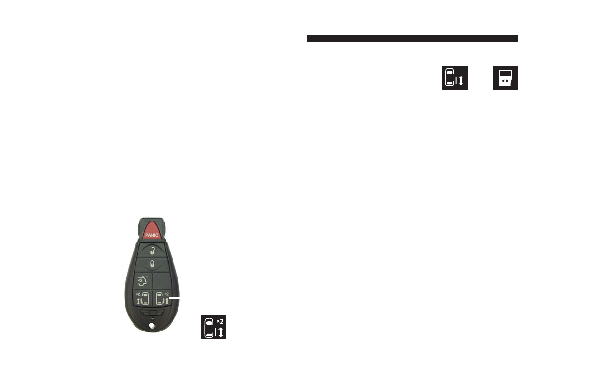
Keyless Entry
Transmitter
Press and
release this
switch two
x
times (
2)
pages 10-13.
Interior mounted control switches
display one of these graphics.
or
One-Touch Control Activation
Entervan power door, kneel and ramp functions are
activated by pressing and releasing a control switch
(press and release remote entry transmitter button
twice).
Open Functions: When activating the Open functions, the power door opens, the kneel system lowers
the rear of the vehicle and the ramp deploys.
Close Functions: When activating the Close functions, the ramp stows, the kneel system raises the
rear of the vehicle and the power door closes.
Manual Operation
The passenger side power sliding door and power
ramp can be manually operated. Read this manual
for further details.
Page 4
Page 7
ENTERVAN OPERATION QUICK REFERENCE GUIDE
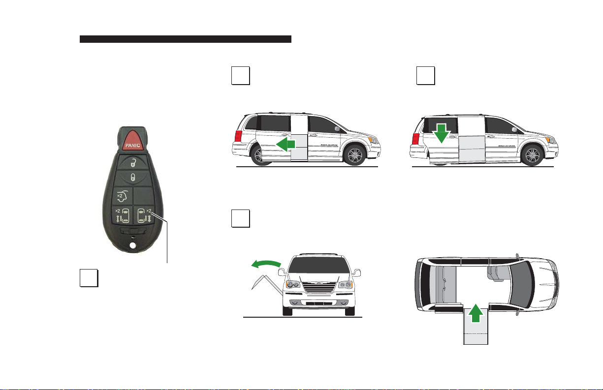
Operating Your New
Entervan Couldn’t
Be Simpler . . .
Just press any one
1
of the buttons like
the one pictured above
or those shown on page
4 (press twice on the key
transmitter). . .
And the sliding door opens
2 3
The ramp deploys Allowing easy entrance!
4
The rear suspension lowers
A
Page 5
Page 8

FEATURES
One-Touch Electronic Control System: The electronic
control system provides simple
one-touch activation of Entervan power functions. For your
convenience, the power features
can be activated using the OEM
remote keyless entry transmitter
or one of the interior switches
detailed on pages 10-13.
Passenger Side Power Slide
Door: The electronic control
system activates the passenger side power slide door for
ramp access. The slide door
and lowered floor configuration
provides 52-1/2" clear vertical
passageway. Note: The driverside sliding door is lowered to
provide clear passage also.
Ramp: The fully automatic
power ramp provides 29-1/4"
usable width. The power ramp
can be manually operated.
Electromechanical Power
Kneeling Rear Suspension:
“Kneeling” is the lowering motion of the electromechanical
rear suspension. The kneel
feature reduces the slope of the
ramp when deployed.
Lowered Floor from Rear
Axle to Firewall: This feature
provides additional headroom
(57-1/4" floor-to-ceiling at center
of van), and further reduces
the slope of the ramp when
deployed. Note: The floorto-ceiling height is reduced by
2-1/2" with OEM interior DVD/
rail system installed. Ground
Clearance: The lowered floor
results in reduced ground clearance. Be aware of limited ground
clearance.
Ground Effects: Exterior colormatched ground effect panels
conceal the lowered floor and
lowered sliding doors.
Floor Track for Wheelchair
and Occupant Securement in
Midpoint Lowered Floor Area:
Floor track provided in the midpoint lowered floor area (Position
C) can be utilized for restraint of
wheelchair passenger(s). Wheelchair capacity at midpoint may
have limitations based on the dimensions of specific wheelchairs.
Forward-Facing Wheelchair
and Occupant Belt/Track
System: One Forward-Facing
Page 6
Page 9

FEATURES
Wheelchair and Occupant Belt
Kit is supplied for the restraint of
one wheelchair and occupant.
The belt kit is used in conjunction with the floor track. Note:
Additional belt kits can be purchased (option).
Quick-Release Front Passenger Seat with Floor Track for
Wheelchair and Occupant Securement: The passenger seat
(Position B) is equipped with
“step & roll” quick-release seat
base attachments (making seat
removal and installation procedures simple). The seat can be
removed and the seat location
can be utilized by a wheelchair
occupant (floor track provided).
Driver Seat: For the wheelchair
occupant who chooses to drive,
this seat (Position A) can be
removed and adaptive driving
systems custom tailored for the
individual can be purchased
from and installed by your local
mobility dealer. The driver’s
seat is equipped with “step &
roll” quick-release seat base
attachments. 56-1/4" floor-to-
ceiling headroom is provided
at both front seating positions.
Auxiliary Power Supply for
Dealer-Installed Power Seat
or Electric Tie-Downs: This
power source is available to
accommodate adaptive driving
systems custom tailored for
the individual (purchased from
and installed by your local
mobility sales representative).
See pages 52-55.
Midpoint
“L”
Track
Front Seat
“L” Track
A
Midpoint
“L” Track
Available Wheelchair Positions
B
C
Front
Seat
“L”
Track
Page 7
Page 10

CAUTION
W
A
RNING
SAFETY PRECAUTIONS
Safety Symbols
SAFETY FIRST! Know That....
All information contained
A
in this manual and
supplements (if included), is provided for your safety. Familiarity
with proper operation instructions
as well as proper maintenance
procedures are necessary to ensure safe, trouble free operation.
Safety precautions are provided
to identify potentially hazardous
situations and provide instruction
on how to avoid them.
D
These symbols will appear throughout this manual and may appear on labels posted on your Entervan.
Recognize the seriousness of this information.
Page 8
B
This symbol indicates
important safety information regarding a
potentially hazardous
situation that could
result in serious
bodily injury and/or
property damage.
Note: Additional information provided to help clarify or detail a specific subject.
C
This symbol indicates
important information regarding how to
avoid a hazardous situation that
could result in minor
personal injury or
property damage.
Page 11

OPERATION
Whenever parking your Entervan
and before utilizing Entervan
power features, always engage
the vehicle transmission in Park
“P” and engage the vehicle
parking brake. Entervan power
function control switches can
be activated only if the vehicle
transmission is in Park or Neutral.
Terminology
“Kneeling” is the lowering motion
of the Entervan electromechanical rear suspension. The term
“deploy” (unfold) indicates the
lowering motion of the ramp to
the deployed position. “Stow”
(fold) is the raising motion of the
ramp to the vertical (stowed)
position.
The terms “Open” and “Close”
refer to sequences of power
functions that will occur when
activated by the One-Touch
electronic control system. When
activating the Open functions,
the power door opens, the kneel
system lowers the rear of the
vehicle and the ramp deploys.
When activating Close functions,
the ramp stows, the kneel system raises the rear of the vehicle
and the power door closes.
One-Touch Control System
Entervan power functions are
managed by the electronic
control system. The control
system can be activated using
the remote keyless entry transmitter or any one of the controls
addressed on pages 10-13.
Do not attempt to interface
aftermarket control systems.
Braun Corporation
Aftermarket Control
Systems Policy:
The Braun Corporation manufactures dedicated control systems
for its products. These control
systems have been designed
and tested for use in conjunction
with specific Braun products.
Braun control systems are the
only control systems authorized
for use with Braun products.
Do not attempt to interface aftermarket control systems without
authorization from The Braun
Corporation. To do so may
result in serious bodily injury
and/or property damage.
Page 9
Page 12

OPERATION
Control Switches
For your convenience, Entervan
power features can be activated
using the OEM remote keyless
entry transmitter or one of the
interior control switches identified
on pages 11-13.
The passenger power sliding door
switches provided on the remote
keyless entry transmitter and in
the overhead console will unlock
the passenger side slide door and
activate the Entervan power door,
kneel and ramp functions.
The power sliding door switches
provided in the center console and
on the wall panels to the front and
rear of the passenger side sliding
door (B-pillar and C-pillar respectively), are accessible to rear
seat passengers including small
children. These control switches
Page 10
will activate Entervan power
functions only if the passenger
side power slide door is unlocked
and the overhead console Master
Lock Out switch is in the ON position. Master Lock Out details are
provided on page 13.
Braun minivan conversions are
designed with safety and simplicity in mind for ease of operation.
If a power function has been
activated that was not intended,
simply press a control switch to
stop or reverse the function. If
the desired function has not been
activated, press the switch again.
Entervan power function control
switches can be activated only
if the vehicle transmission is in
Park or Neutral.
Control Switches
Switches that activate Entervan
power functions at all times:
• Keyless Entry Transmitter
• Overhead Console Passenger
Power Sliding Door Switch
• All Other Switches
The passenger side power slide
door must be unlocked and the
Master Lock Out switch must be
in the ON position before power
functions can be activated.
Page 13

OPERATION
One-Touch Control Activation
Entervan power door, kneel and
ramp functions will be activated
by pressing and releasing
either control switch shown on
this page. Press and release
the remote entry transmitter button twice within five seconds.
Power Sliding Door Lock and
Master Lock Out
The keyless entry and overhead
console switches will activate
Entervan power functions
whether the passenger sliding
door is locked or unlocked. The
Master Lock Out switch does
not prohibit use of these control
switches
.
Remote Keyless Entry
Transmitter
Using the Chrysler remote entry
transmitter eliminates the need
for an additional remote control.
Press and
release this
switch twice
(x2)
Press and release
x
switch twice (
2)
within five seconds.
Overhead Console Switch
A control switch is located on
the overhead console.
Press and release this switch
Press and release
switch displaying
slide door graphic.
Page 11
Page 14
OPERATION
Power Sliding Door Lock and
Master Lock Out
The passenger side power
sliding door must be unlocked
and the overhead console
Master Lock Out switch must
be in the ON position before
the three power sliding door
switches identified here can
activate Entervan power functions.
One-Touch Control Activation
When the above conditions are
met - power door, kneel and
ramp functions will be activated
by pressing and releasing any
of the control switches.
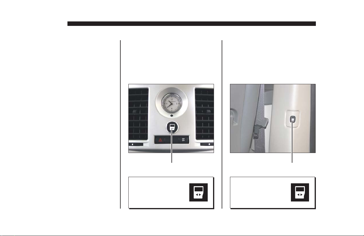
Center Console Switch
For front seat passengers, a
switch is located in the center
console (dashboard).
Press and release this switch
Press and release
switch displaying
slide door graphic.
B-Pillar Switch
A switch is located on the wall
panel ahead of the passenger
slide door (B-Pillar).
Press and release this switch
Press and release
switch displaying
slide door graphic.
Page 12
Page 15
OPERATION
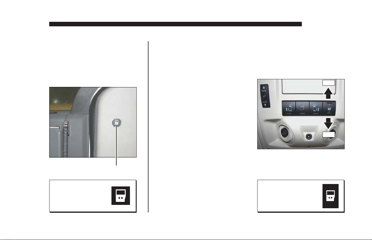
C-Pillar Switch
A switch is located on the wall
panel behind the passenger
slide door (C-Pillar).
Press and release this switch
Press and release
switch displaying
slide door graphic.
Power Sliding Door Master
Lock Out Switch
The Master Lock Out switch
is located in the overhead
console. If the Master Lock
Out switch is in the OFF
position, this OEM feature
will disable the three power
sliding door switches identified at left. Press the switch
to the ON position to enable
the control switches.
Press switch to ON to
enable control switches.
Press switch to OFF to
disable control switches.
Press switch
displaying
this graphic.
ON
OFF
ON
OFF
Page 13
Page 16

OPERATION
Kneel On/Off Switch
The Kneel On/Off switch is
located on the driver side of
the center console. The Kneel
On/Off switch turns the kneel
system on and off only. See
page 16 for further details.
Press this switch to ON
to activate kneel feature.
Press this switch to OFF
to disable kneel feature.
Ramp Access Sliding Door
Press and release the remote
keyless entry transmitter
or one of the interior control switches to activate the
power sliding door (control
switches detailed on pages
10-13). When a control
switch is activated, the door
will open and the Open sequence of functions will continue (rear of vehicle kneels
and ramp deploys).
Once the Open sequence
of functions is complete,
press and release a control
switch to close the door.
The door will close after the
ramp stows and the vehicle
raises (completing the Close
sequence of functions).
Note: If a control switch is activated while the power sliding
door is opening or closing, the
door will reverse direction.
Note: If the power door is
obstructed while opening or
closing, the door will reverse
direction to the fully closed or
fully open position, provided it
meets sufficient resistance.
Note: If the inside or outside
door handles are used while the
power sliding door is activated,
the power sliding door feature
will be cancelled. Simply press
a control switch and the door
will open fully. The power door
can also be opened or closed
manually as detailed at right.
Page 14
Page 17

W
A
RNING
OPERATION
Keep clear of the area in
which the power door operates. Ensure door travel path
is clear. Personal injury or
property damage may occur
during power door operation.
Be sure the door is fully closed
and latched before driving.
Keep clear of area
in which power door
operates. Failure to
do so may result in
bodily injury and/or
property damage.
Power Door Manual Operation
The passenger side power
sliding door can be operated
manually. Unlock the passenger sliding door. Open the
slide door from inside or outside
using the OEM door handles.
Always open the door smoothly.
Avoid using excessive force
when opening and closing the
door.
Note: The ramp obstructs access to the inside door handle.
The OEM handle has been
equipped with an extension
strap.
Extension Strap
Ramp
Page 15
Page 18

OPERATION
Automatic Kneel System
Kneeling is the lowering motion
of the Entervan electromechanical rear suspension. The
kneel system lowers the rear of
the vehicle. Lowering the rear
of the vehicle reduces the slope
of the ramp.
When the electronic control
system is activated to start
the Open functions, the kneel
system starts to lower the rear
of the vehicle at the same time
the power sliding door starts to
open. When the Close functions are activated, the rear of
the vehicle starts to raise at the
same time the ramp begins to
stow.
Kneel On/Off Feature
A Kneel On/Off feature is incorporated in the electronic control
system. This feature provides
the option of kneeling the vehicle
when operating the power door
and power ramp. The Kneel
switch is located on the driver
side of the center console (see
page 14). The Kneel On/Off
switch turns the kneel system on
and off only. The Kneel switch
must be in the On position in
order for the kneeling system to
be activated.
Note: If the Entervan is in the
kneeled position and the Close
functions are activated, the vehicle will raise whether the Kneel
On/Off switch is On or Off.
Note: If the Kneel On/Off
switch is switched from Off to
On during the Open sequence
of functions or within 60
seconds of ramp deployment,
the vehicle will kneel after the
ramp is fully deployed.
Kneel On/Off Switch
Press this switch to ON
to activate kneel feature.
Press this switch to OFF
to disable kneel feature.
Page 16
Page 19

OPERATION
Note: If the Entervan is in the
kneeled position (with ramp
deployed) and the transmission
is disengaged from Park “P,” the
ramp will stow and the vehicle
will raise.
Note: Do not leave your Entervan in the kneeled (lowered)
position for extended periods of
time. Doing so may result in battery drain.
In the event the kneel system is
not functioning properly, have
the kneel system repaired immediately. Do not drive with the
rear of the vehicle in the lowered
position. Attempting to do so will
result in an extremely rough and
unstable ride.
Contact your sales representative or call The Braun Corpora-
tion at 1-800-THE LIFT. One
of our national Product Support
representatives will direct you to
an authorized service center.
Kneel Electrical Override
An electrical override feature is
incorporated in the kneel system.
The override by-passes the electronic control system to electrically power the kneel actuator.
The override is available to raise
the rear of the vehicle only.
The Kneel Override Switch is
located under the driver side
rear bench seat. Press and hold
the switch to release the kneel
system (raise vehicle). Release
the switch when the rear of the
vehicle has raised fully. The
kneel actuator motor will ratchet
(make clicking sound).
Switch is located under driver side
rear bench seat (viewed from rear
with seat in raised position).
Kneel
Override
Switch
Press and hold this switch to
release kneel (raise vehicle).
Page 17
Page 20

OPERATION
CAUTION
Power Ramp Operation
The power ramp is activated by
the electronic control system
using any of the control switches
identified on pages 11-13. When
a control switch is activated to
start the Open functions, the
ramp deploys after the power
sliding door reaches the fully
open position. When the Close
functions are activated, the ramp
stow function begins immediately
(simultaneously with the kneel
system).
If a control switch is activated
while the ramp is in motion
(deploying or stowing), the ramp
motor will stop running. Activating a control switch again will
start the Close functions (ramp
will stow, vehicle will raise and
the door will close).
Note: The power sliding door
must travel from the full closed
position to the full open position in
order for the ramp to deploy.
Note: If the vehicle transmission
is disengaged from Park “P” while
the ramp is deploying (in motion)
or when the ramp is in the fully
deployed position, the ramp will
stow immediately.
Note: If the power ramp is obstructed while deploying or stowing, the ramp motor will stop running, provided it meets sufficient
resistance. Press a control switch
again and the ramp will stow and
the door will close.
Note: When deploying the ramp,
the ramp motor stops running
when the ramp reaches the nearly
horizontal position (approximately
6"- 8" above ground level). The
ramp continues to slowly lower
the remaining distance by the
force of gravity.
Forcing the Ramp: Allow the
power ramp to deploy (unfold
and lower) fully before boarding
the ramp. Forcing the ramp out
or down during the deploy/stow
functions, or boarding onto the
ramp before it is fully-deployed
may result in damage to the
ramp, motor assembly and/or
electronic controller.
Allow ramp to deploy
fully before boarding.
Failure to do so may
result in damage.
Page 18
Page 21

W
A
RNING
Power Ramp Safety
W
A
RNING
Keep clear of
area in which
ramp operates.
Be certain there is adequate clearance outside the
Entervan before deploying the power ramp. Keep
clear of area in which the ramp operates. Be certain
no person or obstruction is within the path of the ramp
when deploying or stowing the ramp. Keep clear of
all power ramp moving parts. Do not attempt to grip
or hold the ramp or ramp folding mechanism during
operation.
Provide adequate
clearance outside
of vehicle to accommodate ramp.
Failure to do so may
result in serious
bodily injury and/or
property damage.
OPERATION
Keep body
parts and
obstructions
clear of the
area in which
the ramp
operates.
Page 19
Page 22
OPERATION
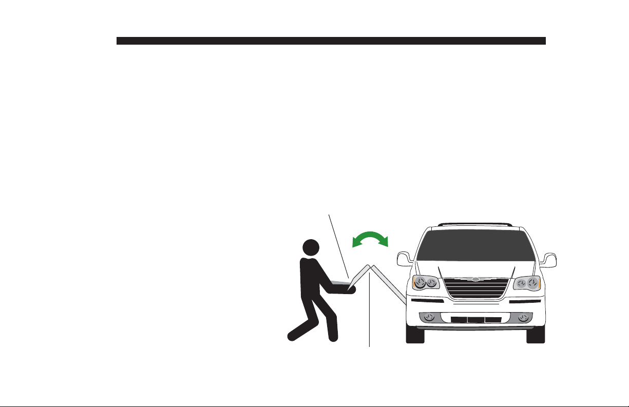
Power Ramp Manual Operation
The power ramp can be manually deployed and stowed. Ramp
manual operation procedures
must be performed by an assistant.
An oval-shaped HAND HOLD
slot is provided on the ramp.
Carefully deploy and stow the
ramp using the HAND HOLD.
The safety precautions addressed in the Power Ramp
Safety section apply to manual
ramp operation also. Read and
become familiar with all ramp
safety precautions.
Keep clear of the area in which
the hinged ramp bi-fold extension
folds and unfolds. Remember to
use good body mechanics when
manually stowing and deploying
the ramp.
Do not release the ramp when
manually deploying or stowing
the ramp. The ramp will free-fall.
Use HAND HOLD to carefully
deploy and stow ramp.
Keep clear of hinge area.
Push the ramp out from inside
the vehicle only if an assistant
is not available and it is absolutely necessary (power failure).
The ramp will free-fall.
Page 20
Page 23

Ramp Electrical Override
An electrical override feature is
incorporated in the power ramp
system. The override by-passes the electronic control system
to electrically power the ramp.
The override is available to stow
(fold) the ramp only.
The Ramp Override Switch is
located rear of the ramp in the
lower wall panel. Press and
hold the switch to stow (fold) the
ramp. Release the switch when
the ramp is fully stowed (stops).
Caution: If you stop pressing
the override switch before the
ramp is fully stowed, the ramp
may free-fall.
OPERATION
Ramp
Override
Switch
Press and hold this switch
to stow (fold) the ramp.
Page 21
Page 24

OPERATION
W
A
RNING
Ramp Safety
Wheelchair passengers and attendants (when applicable), must use basic common sense and good
judgment regarding ramp safety. Each wheelchair
passenger has a unique set of physical abilities,
combined with the physical characteristics of his or
her wheelchair, that dictate the method in which he or
she will enter and exit the Entervan. Consequently,
the procedures for safe operation outlined in this
manual are general in nature. Wheelchair attendants
should be instructed on any special needs and/or
procedures required for safe transport of wheelchair
passengers.
Follow all safety instructions regarding torso restraints, stability, balance, weight distribution and
use of attendants as specified in the owner’s manual
supplied with your wheelchair. Determine, establish
and practice ramp boarding and exiting procedures
under the direction of your health care professional,
your wheelchair representative, and your Entervan
sales representative to ensure your ability to do so
safely.
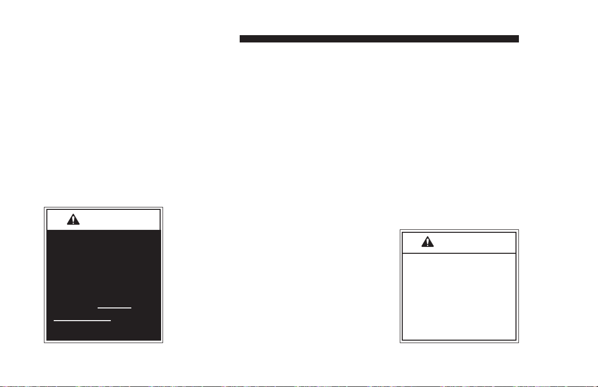
Never board an Entervan ramp if you or your attendant are intoxicated. The wheelchair should be
positioned in the center of the ramp at all times. You
must be able to clearly view the ramp whenever
boarding and exiting the vehicle. The wheelchair
passenger and/or attendant must ensure the ramp is
fully deployed before exiting the vehicle.
It is the responsibility of the wheelchair operator to
enter and exit the
Entervan on the
ramp in the safest
manner.
WheelchairEquipped Occupant
Seat Belts: Wheel-
chair passengers
should position and
buckle their wheelchair-equipped seat
belt (torso restraint),
Position and fasten
the wheelchairequipped occupant
seat belt before
loading onto the
wheelchair ramp.
Failure to do so may
result in serious
bodily injury and/or
property damage.
Page 22
Page 25
as specified by the manufac-
W
A
RNING
Be aware of
ramp slope.
52217
turer, before loading onto a
wheelchair ramp.
Different types of disabilities require different types
of wheelchairs and different types of wheelchairequipped occupant restraint
belt systems (torso restraint).
It is the responsibility of the
wheelchair passenger to have his or her wheelchair
equipped with an occupant restraint (seat belt) under
the direction of their health care professional.
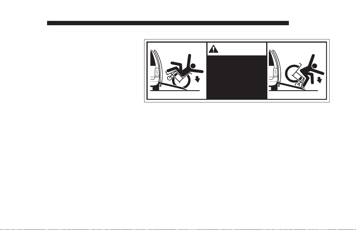
Stabilizing Wheelchairs: Powered and manual
wheelchairs are designed to remain upright and stable
during normal operation. All activities which involve
movement in a wheelchair have an effect on the combined center of gravity of the occupant and wheelchair.
Be aware of the Entervan ramp slope (angle). The
slope of the ramp has a direct effect on the center of
gravity. Keep in mind your center of gravity and your
ability to maintain stability and balance.
OPERATION
Do not operate your wheelchair on the Entervan
ramp without assistance if you are unable to
maintain stability and balance. Counterbalance
devices (anti-tippers) may be available from your
wheelchair representative to enhance stability and
balance.
Do not tilt your wheelchair without assistance.
Operate the wheelchair at a slow and constant
speed when on the ramp. Do not accelerate suddenly when on the ramp. Do not raise the front
wheelchair wheels (pull wheelie) when on the
Entervan ramp.
Page 23
Page 26

OPERATION
The aid of an attendant stabilizing the wheelchair
is recommended for optimum safety. Wheelchair
passengers who intend to enter and exit their Entervan without the assistance of an attendant must
determine the safest and most practical method
and orientation of entering and exiting the Entervan
based on the physical characteristics of their personal wheelchair and his or her physical capabilities
to maintain stability while the wheelchair is in motion
on the Entervan ramp.
Wheelchair Attendants: When assisting a wheelchair occupant, remember to use good body mechanics. When the wheelchair is on the ramp, the
attendant must grasp the push handles (or other)
securely. Detachable wheelchair parts such as arms
or leg rests must never be used for hand holds or lifting supports. Doing so could result in the detachable
parts being inadvertently detached from the wheelchair resulting in possible injury to the wheelchair
occupant and/or the attendant.
Wheelchair Orientation and Securement During
Transport: The wheelchair and occupant must face
the front of the vehicle and must be secured using
the Forward-Facing Wheelchair and Occupant Belt
and Track System when riding in the Entervan. See
pages 25-33 for details.
Page 24
Page 27

WHEELCHAIR AND OCCUPANT RESTRAINT
One Forward-Facing Wheelchair
and Occupant Belt Kit is supplied
for the restraint of one wheelchair
and occupant (details follow). “Ltrack” is mounted in four locations
in the vehicle for belt securement
(shown in Figure 1).
Note: Wheelchair passengers
shown at right depict the available
seating positions. Wheelchair
capacity at Midpoint (Position C)
may have limitations based on the
physical dimensions of specific
wheelchairs. Additional ForwardFacing Wheelchair and Occupant
Belt Kits must be purchased for
the restraint of each additional
wheelchair passenger.
The Entervan offers the following
options for placement and securement of wheelchair passengers.
Driver Seat: This seat (Position
A) can be removed and adaptive
driving systems custom tailored
for the driving wheelchair occupant can be purchased from
and installed by your local sales
representative.
Front Passenger Seat with Floor
Track: The passenger seat (Posi-
tion B) can be removed and the
seat location can be utilized by a
wheelchair occupant.
Midpoint Lowered Floor Area
with Floor Track: The Midpoint
lowered floor area (Position C) can
be utilized by wheelchair occupants (capacity limitations apply).
Refer to the following guidelines,
illustrations, photos and instructions for proper use of the belt and
track restraint system.
Midpoint
“L”
Track
Front Seat
“L” Track
A
C
Midpoint
“L” Track
Figure 1
B
Front
Seat
“L”
Track
Page 25
Page 28

W
A
RNING
WHEELCHAIR AND OCCUPANT RESTRAINT
No product developed
to date can guarantee
successful securement
of the wheelchair, even
at low speeds, in the
event of an accident.
The Braun Wheelchair
and Occupant Belt/Track
System does meet the
most widely referenced
Federal Motor Vehicle
Safety Standards used
for contemporary
restraint equipment.
However, this equipment
does not ensure stability
of the wheelchair in the
event of an accident at
any speed.
Wheelchair Securement: Four
adjustable over-center buckle
belts are provided for securement of the wheelchair (two for
the front and two for the rear).
The belts are equipped with one
keeper fitting (attachment) which
installs in the vehicle-mounted
“L” track (details on pages 28
and 29). A hook is positioned
on the opposite end of the belts
for attachment to a solid frame
member of the wheelchair. Do
not attach belts to detachable
wheelchair components such as
armrests or leg rests. Front and
rear belt tension is required.
Refer to the illustrations, photos
and instructions on pages 28-33
for belt operation procedures.
Over-Center
Belts
(four supplied)
Lap Belt
Extension
(Midpoint)
Note: Two lap belt
extensions are supplied
(as shown). Midpoint
and front seat lap belt
extensions are not
interchangeable.
Lap Belt
Extension
(Front Seats)
Page 26
Page 29

WHEELCHAIR AND OCCUPANT RESTRAINT
Wheelchair Passenger Securement: Two lap belt
extensions are supplied for securement of the wheelchair occupant. The lap belt extensions are equipped
with a keeper fitting (attachment) which installs in the
vehicle-mounted “L” track. A female receptacle is
positioned on the opposite end of the extension for
attachment to a Chrysler factory-installed upper torso
lap and shoulder belt.
Note: The midpoint lap belt extension is a standard
belt style assembly (adjustable). The front seat
extension is equipped with a rigid cable (nonadjustable). See photos on page 26. Lap belt extensions
are not interchangeable. Attachment procedures
are identical. See the illustrations on pages 30 and
31 and photos on page 33.
Operate the Chrysler lap and shoulder belt as
instructed in your Chrysler owner’s manual. Follow
all safety precautions. Connect the Chrysler lap and
shoulder belt to the lap belt extension. Position the
upper torso (shoulder) belt across the center of the
shoulder. Position the lap belt low across the front of
the pelvis (near hip). See the illustrations on pages
30 and 31 and photos on page 33.
Position of the lap belt buckle, after adjustment, is to
be located near hip position. The belt is to be worn
low and snugly. Adjustment of the lap belt extension is
to be made at adjuster buckle. Wheelchair occupant
restraints should not be held away from the body by
wheelchair components such as armrests or wheels.
Keep belts clear of sharp objects. Do not alter belts.
Do not interchange belts from one position to another.
Keep the supplied belts together as a complete set.
Belt and Track Maintenance: Inspect belt assemblies frequently. Any defects such as belt cuts, fraying
or malfunctioning call for replacement of the entire belt
assembly. “L” track must be clean and not worn, bent
or otherwise damaged (prohibiting proper belt attachment). If there is any sign of damage, wear, abnormal
condition or improper operation of belts, belt hardware
(hooks, keepers, latch plate, receptacle), or track, discontinue use and replace components immediately.
Severe conditions (weather, environment, heavy
usage, etc.) may require more frequent inspections.
Exposure to severe conditions will dramatically reduce
the life of the system.
Page 27
Page 30

WHEELCHAIR AND OCCUPANT RESTRAINT
12"
Side View
Wheelchair Reference Plane
Rear
Securement
Points
30°
45°
10°10°
Side ViewRear View
Figure 2
Front
Securement
Points
40°
60°
12"
25° 25°
Front View
Restraint Belt Angles
Locate wheelchair in forward-facing position centering wheelchair squarely within “L” track. The front
and rear belts, when attached, should create angles
approximately as shown in Figure 2. Preferred
angles and locations of belts from wheelchair securement points to vehicle anchor points are shown.
Front tie-downs should be angled out far for lateral
stability when possible. Note: These are optimum
angles and cannot be achieved in some cases.
Keeper Fitting and “L” Track Attachment
Instructions
The belts supplied in the Forward-Facing Wheelchair
and Occupant Belt/Track System are equipped with
keeper fittings (attachments) which engage the “L”
track. Engage and release the keeper fittings as detailed and shown on the following page. Note: Refer
to pages 32 and 33 for belt attachment and release
procedures.
Page 28
Page 31

WHEELCHAIR AND OCCUPANT RESTRAINT
A
Keeper
“L” Track
Keeper Fitting and “L” Track
Attachment Instructions
a. Push down
on keeper.
To Engage Keeper Fitting:
1. Insert keeper fitting into
track (align two engagement feet with holes in
track). See Photo A.
2. Push down on fitting
Align engagement feet with holes. b. Slide keeper 1/2 slot in either direction.
and slide fitting 1/2 slot
in either direction until it
C
clicks and locks in position (see Photos B and
a. Lift plunger.
C). Pull firmly on belt to
ensure fitting is locked in
track.
To Release Keeper Fitting:
Lift plunger and slide fitting
1/2 slot in either direction
and lift fitting out of track.
Fully-engaged Keeper
b. Slide keeper and lift.
B
D
Page 29
Page 32

WHEELCHAIR AND OCCUPANT RESTRAINT
Keeper
“L” Track
Keeper
Over-center
Buckle Belt
Over-center
Buckle Belt
OEM Installed Upper Torso Lap
and Shoulder Harness
Over-center
Buckle Belt
Lap Belt
Over-center
Buckle Belt
Extension
(see note at right)
Figure 3
“L” Track
Lap Belt Extensions: Two lap
belt extensions are
supplied. Midpoint
and front seat lap
belt extensions are
not interchangeable. Midpoint lap
belt extension shown
in Figures 3 and 4.
Front seat extension
is rigid cable (shown
on page 26).
Page 30
Page 33

WHEELCHAIR AND OCCUPANT RESTRAINT
Note: Generic seat position
shown. Attachment procedures
are identical for all positions.
Photos on pages 32 and 33
depict securement of wheelchair
in midpoint position.
Keeper attachment
details are provided
on page 29.
Keeper
“L” Track
“L” Track
Over-center
Buckle Belt
Over-center
Buckle Belt
OEM Installed Upper Torso
Lap and Shoulder Harness
Figure 4
Adjustable
Lap Belt
Extension
Keeper
“L” Track
“L” Track
Page 31
Page 34

WHEELCHAIR AND OCCUPANT RESTRAINT
E
Over-Center Belt
Attachments
1. Connect chair
hook to a solid
frame member of
the wheelchair (as
shown in Photo E).
2. Position and
connect belt keeper
Hook
Keeper
F
fitting (attachment)
to appropriate track
anchorage point
(slots). Attach
keeper as detailed
on page 29.
Pull firmly on belt
to ensure fitting is
locked in track.
Note: Belt angles
should be as shown
in Figure 2 on page
28.
3. With buckle open,
G
pull loose end of belt
until tight (see Photo
G). While holding
the loose end with
one hand, close the
lever of the clamp
(buckle) down until it
locks. See Photo H.
4. Connect Velcro
tabs to keep excess
belt off floor. See
Photo I).
H
Repeat procedures
for all belts.
Note: Check to see
that front and rear
belts are tight and
the chair is secure
enough that it does
not have any movement. Lock wheelchair brakes.
™
Belt Release: Press
lever clamp (lock) to
release tension on belt.
Velcro™
Tabs
I
J
Page 32
Page 35

WHEELCHAIR AND OCCUPANT RESTRAINT
K
Extension Belt
Extension Belt
M
Receptacle
Chrysler Lap
and Shoulder Belt
Lap and Shoulder Belt Attachments
Refer to Photos K-N.
1. Position and connect the adjustable lap belt extension keeper fitting
(attachment) to appropriate track anchorage point (slots). Attach keeper
as detailed on page 29. Pull firmly
on belt to ensure fitting is locked in
track.
2. Connect the lap and shoulder belt
to the lap belt extension (insert latch
plate in female receptacle). Position
the upper torso (shoulder) belt across
the center of the shoulder. Position
the lap belt low across the front of the
pelvis (near hip). See Photos K-N.
Wheelchair occupant restraints
should not be held away from the
body by wheelchair components such
as wheelchair armrests or wheels.
Chrysler
Lap
and
Shoulder
Belt
L
Receptacle
N
Extension
Belt
Page 33
Page 36
CAUTION
W
A
RNING
SEAT REMOVAL AND INSTALLATION
Front Seats: In an effort to
produce vehicles that can be
configured to meet a variety of
customer needs, the driver and
passenger seat bases have
been designed so they may be
removed. This feature allows
the owner and sales representative to determine the appropriate
seating arrangement to accom-
Park vehicle and
turn engine off
before removing
or installing seats.
Failure to do so may
result in serious
bodily injury and/or
property damage.
modate owner needs. Once the
desired seat arrangement is determined, all power seat electrical
harnesses must be reconnected to
the appropriate fixed seat positions.
Driver’s and passenger’s side front
seats are equipped with “step &
roll” quick-release seat base attachments that engage recessed
floor strikers (supports). The “step
& roll” quick-release front seat is
installed and removed as detailed
on pages 40-43 of this manual.
Power Seats: Entervan front
seats are equipped with electrical
wiring harnesses to accommodate optional equipment such as
heated seats, air bags, etc. Be-
fore removing seats, be certain
all seat electrical harnesses are
disconnected.
When seats are removed, the
seat electrical harness plug
must be connected to the
receptacle provided at the top
of the seat base. See Photos
B and D on page 37 of this
manual.
Adjustable Pedals: The adjustable brake and accelerator
pedal feature is disabled when
the driver seat is removed.
Disconnect seat
wiring harness
before removing
seat. Failure to do
so may result in
property damage.
Page 34
Page 37

SEAT REMOVAL AND INSTALLATION
When positioning seats, it is your
responsibility to reconnect all
seat electrical harnesses. Failure
to properly connect power seat
electrical harnesses may result
in power seat functions being
disabled and/or the air bag light
illuminating.
Entervan front seats are
equipped with an exclusive “step
& roll” quick-release system.
Refer to the seat removal and
installation instructions provided
in this manual. Note: Driver and
passenger side front seats are
not interchangeable.
Contact your sales representative or call The Braun Corporation
at 1-800-THE LIFT if any of this
information is not understood.
Seat Base Rear Covers
Entervan front seats are equipped
with easy to remove rear seat
base covers. The covers must
be removed when removing and
installing seats. Refer to photo
at right. Simply pull back on the
covers to remove them (Velcro
®
secured). Align and push covers into position when reinstalling
seats.
Caution: Do not contact and
damage the seat base electrical
harness when removing and installing the rear seat base covers.
Pull back on Rear Seat Cover
Page 35
Page 38

BLANK for LAYOUT
Page 36
Page 39

SEAT REMOVAL AND INSTALLATION
A
C
Seat
Harness
Front Seat Wiring Harnesses
and Receptacles
An electrical harness receptacle
is located to the rear of each
seat base in the wall (at “B”
pillar). The seat wiring harness
plug connects to the receptacle
socket (screw-on connector
details on pages 38 and 39 of
this manual).
Before removing seats, be
certain seat wiring harnesses
are disconnected.
When seats are removed, the
seat electrical harness plug
must be connected to the
receptacle provided in the seat
base. See Photos B and D.
B-Pillar
Receptacle
Seat Storage
Receptacle
B
Seat
Plug
D
Page 37
Page 40

SEAT REMOVAL AND INSTALLATION
CAUTION
W
A
RNING
Disconnect seat
wiring harness
before removing
seat. Failure to do
so may result in
property damage.
Connect front seat
wiring harness plug
to socket provided
at top of seat base
before removing front
seat. Failure to do so
may result in serious
bodily injury and/or
property damage.
When installing seats, be certain seat wiring harnesses are
reconnected. Failure to do so
may result in power seat functions
being disabled and/or the air bag
light illuminating.
Adjustable Pedals: The adjustable brake and accelerator pedal
feature is disabled when the driver
seat is removed.
Screw-on Connectors
Front seat wiring harnesses are
equipped with a screw-on connector (plug). Operate connectors as
detailed here and on page 39.
A label is posted on the seat wiring
harness plug which identifies the
top of the connector (“TOP” decal
28891). Position the plug with the
“TOP” label facing up when con-
necting the plug to either receptacle socket. Use this feature as
an alignment guide.
Note: Alignment grooves (slots)
are provided in receptacle sockets. Receptacle sockets have a
single wider alignment groove that
is positioned at 12 o’clock (shown
on page 39). Seat wiring harness
plugs are equipped with mating
alignment guides (ears).
Page 38
Page 41

SEAT REMOVAL AND INSTALLATION
Turn this
knurled grip.
Disconnect
Position plug with
“TOP” label up.
TOP
Receptacle
(socket)
Connect
28891
Seat Wiring
Harness Plug
Screw-on Connectors
To Connect: Align the seat
harness connector by positioning the plug with the “TOP”
label facing up. Align the seat
harness connector alignment
guides with the receptacle
socket alignment grooves (will
only connect one way).
Carefully insert the seat harness plug in the receptacle
socket. Turn seat harness connector large diameter knurled
grip clockwise fully (turn gripper
nearest to socket).
To Disconnect: Turn seat harness connector large diameter
knurled grip counterclockwise
and disengage connectors.
Alignment Groove
(at 12 o’clock)
4
95
15 10
22 16
28 23
33 29
37 34
1
Receptacle Socket
Alignment Guide
4
1
5
10
16
23
29
34
9
15
22
28
33
37
Seat Harness Plug
Page 39
Page 42

SEAT REMOVAL AND INSTALLATION
Front Seat Bases
“Step & roll” quick-release seat
base attachments engage recessed floor strikers (supports).
A foot-activated release pedal
is located at the rear of the seat
base. Stepping on the pedal
disengages the attachments
and deploys the seat base rear
wheels.
Note: For ease of disengagement, move the seat to the full
forward and upright position before removing seat(s). Push the
seat back forward and upward
while stepping on foot pedal
(ensures full deployment of rear
wheels).
Foot
Pedal
Push seat back forward and upward
while stepping on foot pedal.
Front Seat Removal Instructions
1. Move seat to full forward and
upright position.
2. Caution! Disconnect seat
wiring harness before
removing a front seat base.
Connect harness to seat base
socket. See page 37-39 for
wiring harness details.
3. Depress foot pedal (push
down). Note: Push seat back
forward and upward while
stepping on foot pedal. See
Photos and Figures A-D.
4. Pull up and back on the rear
of seat (deploy front wheels).
See Figures E and F.
5. Roll seat base out of vehicle
as shown.
Page 40
Page 43

SEAT REMOVAL AND INSTALLATION
A
Illustrations depict seat base only.
Stowed
Seat Base
Foot Pedal
B
Stowed
Seat Base
Engaged Strikers
Depress
foot pedal.
C
D
Depress pedal (a)
and lift seat (b).
E
b
a
Deployed Rear Wheels
b
a
Deployed Rear Wheels Deployed Front Wheels
Deployed Front Wheels
F
Pull seat up and back.
Roll seat out of vehicle
Page 41
Page 44

SEAT REMOVAL AND INSTALLATION
W
A
RNING
Front Seat Bases
“Step & roll” quick-release seat
base attachments engage recessed floor strikers (supports). A
foot-activated release pedal is located at the rear of the seat base.
A cross bar is positioned directly
under the pedal. Stepping on the
bar engages the rear seat base attachments to lock the seat base.
Seat attachments
must be fully latched
in floor supports be-
fore occupying seats
or operating vehicle.
Failure to do so will
result in serious
bodily injury.
Engagement
Bar
Front Seat Installation
Instructions
1. Roll seat base into position, just
behind the floor mounted strikers.
See Figures A and B. Move seat
base forward to engage front
strikers. See Figures C and D.
Note: Position outside of seat
base alongside wall panel for
easy alignment.
2. Depress rear cross bar (push
down) to stow rear wheels and
engage rear seat attachments
with floor strikers. See Figures
C-F. Lift seat to ensure floor
strikers are locked in seat attachments.
3. Connect (plug) seat electrical
harness to B-pillar receptacle.
See page 37.
Page 42
Page 45

SEAT REMOVAL AND INSTALLATION
A
Floor Strikers
B
Roll seat into position.
Floor Strikers
Roll seat
into position.
C
a
Engaged Front Strikers
D
Engage front strikers (a) and
depress engagement bar (b).
a
Engaged Front Strikers
b
Engagement Bar
b
E
Engaged Strikers
F
Stowed (locked)
Engaged Strikers
Stowed
(locked)
Seat Base
Seat Base
Page 43
Page 46

SEAT REMOVAL AND INSTALLATION
W
A
RNING
Third Row Seats
Third row 60/40 split bench seats
have been modified during conver-
sion procedures. Seat backs can be
folded down to the flat position and
tipped forward to provide full access to
rear floor storage compartments. The
Stow ’n Go (stow in floor) feature is
not available.
Seat removal is allowed for the driver
side section of the seat (instructions
on opposite page). The electronic
control module assembly is mounted
under the passenger side section of
the seat. Removal of the passenger
side section of the seat is prohibited*.
* Should removal of the passenger
side section of the third row seat
be imperative, contact The Braun
Corporation at 1-800-THE LIFT
A Braun Product Support representative will direct you to an authorized
service technician.
®
.
Folding (tipping) Third Row Seats
Seat backs can be folded down to
the flat position and tipped forward.
Seats must be returned to the full
stowed (locked) position before
driving.
To Fold (tip forward) Third Row
Seats
1. From the rear of the vehicle, fold
down the back of the bench seat
(pull release strap #1).
2. Pull the release strap at the rear
of the seat (between seat base
and floor), and lift and fold (tip)
the seat forward.
To Unfold (rotate rearward) Third
Row Seats
Carefully (slowly) rotate and lower
seat rearward to stowed position.
Ensure the rear spring-loaded at-
tachments engage floor strikers.
Raise the seat back (pull release
strap #1) and attempt to move
seat back and forth.
Caution: Use extra care when
lowering passenger side section
of seat. Do not slam seat down
or allow seat to drop (free-fall).
Doing so may result in damage
to the electronic control module
assembly.
Install seats as
specified before
occupying seats or
operating vehicle.
Failure to do so may
result in serious
bodily injury and/or
property damage.
Page 44
Page 47

SEAT REMOVAL AND INSTALLATION
Third Row Seat Removal:
Note: Removal of the passenger
side section of the seat is prohibited*. Policy detailed on previous
page.
1. From the rear of the vehicle, fold
down the back of the bench seat
(pull release strap #1).
Linkage Arm
Securement Bolt
2. Pull the release strap at the rear
of the seat (between seat base
and floor), and lift and fold (tip)
the seat forward. Note: Push
top of linkage rod forward to stabilize seat (over center position)
3. Remove the bolt securing the
linkage arm to the floor-mounted
bracket.
(40) Section(60) Section Controller Assembly
4. Remove E-ring retaining clips
from the pivot pins securing the
front floor mounts.
5. Remove the pivot pins.
6. Carefully remove seat.
Third Row Seat Installation:
Reverse removal procedures.
E-Ring Retaining Clip
Pivot Pin
Page 45
Page 48

LIMITED WARRANTY
In accordance with the Chrysler 5 year/100,000
mile corrosion warranty, The Braun Corporation warrants to the purchaser of its Entervan conversion that
it will repair (or replace at Braun’s sole option) any
defect in material or factory workmanship in the metal
fabrication on or of the frame, floor and lowered door
extension for a period of 5 years or 100,000 miles on
the odometer, whichever occurs first. The Braun Corporation further warrants to the purchaser that it will
Years/Miles in Service
Entervan frame and floor structural components
Entervan ramp, door and associated structural components
36 Months
or
36,000 Miles
(whichever comes first)
Entervan electrical components including but not limited to switches,
wires, connectors and the controller
Entervan electromechanical kneel systems including but not limited
to electric actuator, chain, pulleys and associated hardware
repair (or replace at Braun’s sole option) any defect
in material or factory workmanship for the remainder
of the modifications and alterations for associated
parts for a period of 36 months or 36,000 miles,
whichever occurs first. For clarification purposes,
the following chart outlines The Braun Corporation
Entervan warranty coverage. Refer to your Chrysler
warranty information booklet for all Chrysler OEM
(factory) limited warranty details.
Specific Area Covered
Page 46
Page 49

LIMITED WARRANTY
Years/Miles in Service
36 Months
or
36,000 Miles
(whichever comes first)
Corrosion Limited
Warranty
Outer Panels
5 Year or
100,000 Miles
(whichever comes first)
All Panels
(Exceptions)
3 Years/Unlimited
Miles
Specific Area Covered
Entervan appearance items including but not limited to interior
floor covering and slide door lowered extension assemblies.
Corrosion Limited Warranty:
Outer Panels: Entervan frame, floor and lower door modification
metal fabrication corrosion applies to perforation only. Entervan
lower slide door modification corrosion applies to outer-body sheet
metal and paint. Perforation is a rust-through condition such as an
actual hole in the metal.
All Panels (Exceptions): Cosmetic or surface corrosion (resulting
from stone chips for example) would not be covered or repaired
under this coverage. If corrosion does not cause holes, and is not
the result of usage and/or environmental conditions, repair coverage lasts for 3 years/unlimited miles.
Page 47
Page 50

LIMITED WARRANTY
Both the 5 year/100,000 mile corrosion and the
3 year/36,000 mile limited warranties described on
previous page commence on the date the conversion is put into service, providing the warranty registration card is completed and received by The Braun
Corporation within thirty days of the purchase.
The Braun Corporation agrees to repair or
replace any of its Entervan factory-installed parts
found to be defective within the appropriate warranty period or mileage. This limited warranty also
covers the cost of labor for the repair or replacement
of said parts for three years provided that the repair
is authorized by The Braun Corporation and carried
out by an authorized service establishment (a Braun
labor schedule determines the cost allowance for
repairs). The Braun Corporation will not honor any
warranty claim for repairs or replacement of parts
unless the claim is submitted with the appropriate
factory warranty authorization data and the repairs
or replacement of the parts are completed by a factory-authorized repairman. The factory authorization
data, together with the name and location of the fac-
tory-authorized repairman, can be obtained by either
written or telephone contact with The Braun Corporation at the addresses appearing in this manual.
The return authorization procedure must be adhered to in order to process any warranty and repair
claims (details on following page).
The Braun Corporation reserves the right to designate where any warranty work is to be performed.
The Braun Corporation also reserves the right to
examine any defective workmanship or part prior to
any authorization of necessary repairs. This Entervan limited warranty is not intended to replace or
substitute any other warranties issued by the original manufacturer of the vehicle or other suppliers of
components. This limited warranty shall not apply to
any part or workmanship that may become defective
due to misuse, neglect, accident or other casualty,
modifications or alterations or unauthorized repairs.
Further, this limited warranty shall not extend to parts
or workmanship that may become defective because
Page 48
Page 51

LIMITED WARRANTY
of the failure of anyone to operate the same in accordance with the printed instructions of The Braun
Corporation or because of operation of the same
beyond its capacity.
This limited warranty does not cover normal maintenance, service, or periodic adjustments necessitated by use or wear.
Second buyers of a Braun Entervan conversion may transfer the remaining warranty, if any,
by obtaining a transfer of warranty application from
The Braun Corporation. This application must be
returned to The Braun Corporation within thirty days
from the date you purchase the vehicle and proof
of the date of purchasing must be supplied with the
transfer of warranty application. There will be a minimum warranty transfer fee.
The Braun Corporation shall not be liable for
any incidental or consequential damages resulting from any breach of warranty.
The Braun Corporation shall not be liable for towing charges, travel and lodging, or any other expense
incurred due to the loss of use of vehicle or other
reason.
To the extent any implied warranties exist by
operation of federal or state law, such implied
warranties are limited in duration to the period of
the express limited warranty herein.
Return Authorization Procedure
When processing any warranty claims (parts, repairs,
etc.), all requests must be processed through the
Braun Corporation Product Support Department.
®
Call 1-800-THE LIFT
during working hours. Product
Support will issue a Return Material Authorization
(RMA) number and detail the procedures required for
processing returns and/or authorizing credit.
The last eight digits of the vehicle identification num-
ber (VIN) must be provided when filing a warranty
claim or ordering parts.
Page 49
Page 52

PREVENTIVE MAINTENANCE
Maintenance is necessary to
ensure safe and trouble free
Entervan
operation. General preventive maintenance consisting
of inspections of your Entervan
systems along with cleaning and
lubricating procedures should be
a part of your routine (lubrication requirements are minimal).
Keeping the passenger slide door
lower track pan free of debris,
ice and snow is one of the most
effective preventive maintenance
practices to exercise. Regular
preventive maintenance procedures will increase the service
life of the Entervan, as well as
enhancing safety.
During routine inspections, operate all Entervan systems and
note the following (as equipped):
• Is the power source adequate or
weak?
• Does the electronic control system function properly?
• Do the control switches function
properly?
• Does the kneel feature function
properly?
• Does the power door function
properly?
• Does the ramp deploy and stow
properly?
• Inspect wheelchair and occupant restraint belts, buckles and
hardware for damage, wear,
abnormal condition or improper
operation.
Entervan ramps are equipped
with sealed bearings and Teflon™ bushings to decrease wear,
provide smooth operation and extend the service life of the ramp.
A “dri-film” style of light oil should
be applied to the ramp inboard
pivot points and outboard ramp
extension hinge (goes on wet then
dries). Lubricants of this type
are available that do not attract
dust or debris. Clean the components and the surrounding area
before applying lubricants. Use
of improper lubricants can attract
dirt or other contaminants which
could result in wear or damage to
components.
Inspect and clean as detailed
frequently and routinely (minimum
four weeks or 100 cycle intervals).
Lubricate the ramp as specified
approximately every three months.
Note: These intervals are a
general guideline and will vary
according to frequency of use and
conditions. Exposure to severe
conditions (weather, environment,
heavy usage, etc.) may require inspection and maintenance procedures to be performed more often.
Page 50
Page 53

PREVENTIVE MAINTENANCE
W
A
RNING
Preventive maintenance visual inspections, cleaning and lubrication
procedures do not take the place
of the procedures specified in
the Maintenance and Lubrication
Schedule provided in the Entervan
service manual. The procedures
outlined in the Maintenance and
Lubrication Schedule must be
performed at the recommended
scheduled intervals by an
authorized Braun Corporation
service representative who has
attended and been certified by
The Braun Corporation Sales
and Service School.
If there is any sign of damage,
wear, abnormal condition or
improper operation, discontinue
Entervan use immediately.
Contact your sales representative or call The Braun Corporation
at 1-800-THE LIFT. One of our
Product Support representatives
will direct you to an authorized
service technician who will inspect
your Entervan.
Maintenance and lubrication procedures
must be performed
by authorized service personnel as
specified in the
applicable Entervan
service manual.
Failure to do so may
result in serious
bodily injury and/or
property damage.
Page 51
Page 54
AUXILIARY POWER SUPPLY / BELOW FLOOR OBSTRUCTIONS
CAUTION
W
A
RNING
Note: The technical information
provided on pages 52-55 of this
manual is service related. If you
are having an electrical tie-down,
power seat or other auxiliary
electrical device installed in your
Entervan, this information should
be supplied to the technician.
Otherwise, disregard this section.
Do not connect
auxiliary devices to
vehicle battery. Doing
so may result in damage to electrical system and/or electronic
components.
Auxiliary Power Supply: Do not
connect auxiliary devices directly
to the vehicle battery. Doing so
may result in damage to electrical system and/or electronic
components.
Two fuse blocks are provided
as an auxiliary power source for
dealer-installed auxiliary electrical device(s). Fuse block details
and specifications are provided
on page 53. The fuse blocks are
located in the bottom of the center
dash console.
Below Floor Obstructions:
When installing aftermarket equipment in an Entervan, obstructions
below the floor must be avoided.
Obstructions include wiring, fuel
system, brake lines, etc. Installers
must be aware of these obstructions.
Refer to the illustration on page 55
to avoid contacting or damaging
vital components under the floor.
Risk of electrical fire!
Install and electrically
terminate auxiliary
electrical device as
specified by device
manufacturer.
Page 52
Page 55

AUXILIARY POWER SUPPLY / BELOW FLOOR OBSTRUCTIONS
Fuse Blocks: Two fuse blocks
are provided for use as an auxiliary power source (one Ignition
fuse block and one Battery fuse
block).
The Battery fuse block provides
power at all times (independent of
the vehicle ignition). The Ignition
fuse block supplies power only
when the vehicle ignition is on.
The installer is responsible for
supplying the correct gauge wire
and fuse for the particular device
to be attached to the fuse block
(as specified by the manufacturer
of the device).
Ignition Fuse Block: The total
maximum load must not exceed
40 amperes.
Battery Fuse Block: The total
maximum load must not exceed
40 amperes.
Note: If installing an auxiliary
electrical device that requires
more than a 40 ampere power
source, an alternative power
source must be provided.
Under Dash Fuse Blocks
OPEN
OPEN
F1
F3
OPEN
F2
F4
OPEN
29429
OPEN
30
F1
F2
29428
F3
F4
20
30
Fuse Block Access: The fuse
blocks are located at the bottom
of the center console. Remove
upper console panel (3 fasteners
per side). Remove lower panel.
Note: The fuse blocks are part
of the gateway electrical assembly. Two grounding studs are
also provided.
OEM Fasteners
Page 53
Page 56

AUXILIARY POWER SUPPLY / BELOW FLOOR OBSTRUCTIONS
W
A
RNING
W
A
RNING
Below Floor Obstructions
When installing an electrical tiedown, power seat or other auxiliary electrical device in an Entervan,
obstructions below the floor must
be avoided. Obstructions include
wiring, fuel system, brake lines,
etc. Installers must be aware of
these obstructions.
Check for obstructions such as wires,
gas lines, exhaust,
etc. before drilling or
cutting through floor.
Failure to do so may
result in serious
bodily injury and/or
property damage.
Refer to the illustration on the
following page when installing
aftermarket equipment to avoid
contacting or damaging vital
components under the floor.
Drilling or cutting into such
obstructions may result in
potential hazards as well as
property damage.
Note: Some wiring harnesses
shown may not be present.
Avoid all harness locations.
Risk of electrical fire!
Install and electrically
terminate auxiliary
electrical device as
specified by device
manufacturer.
Page 54
Page 57
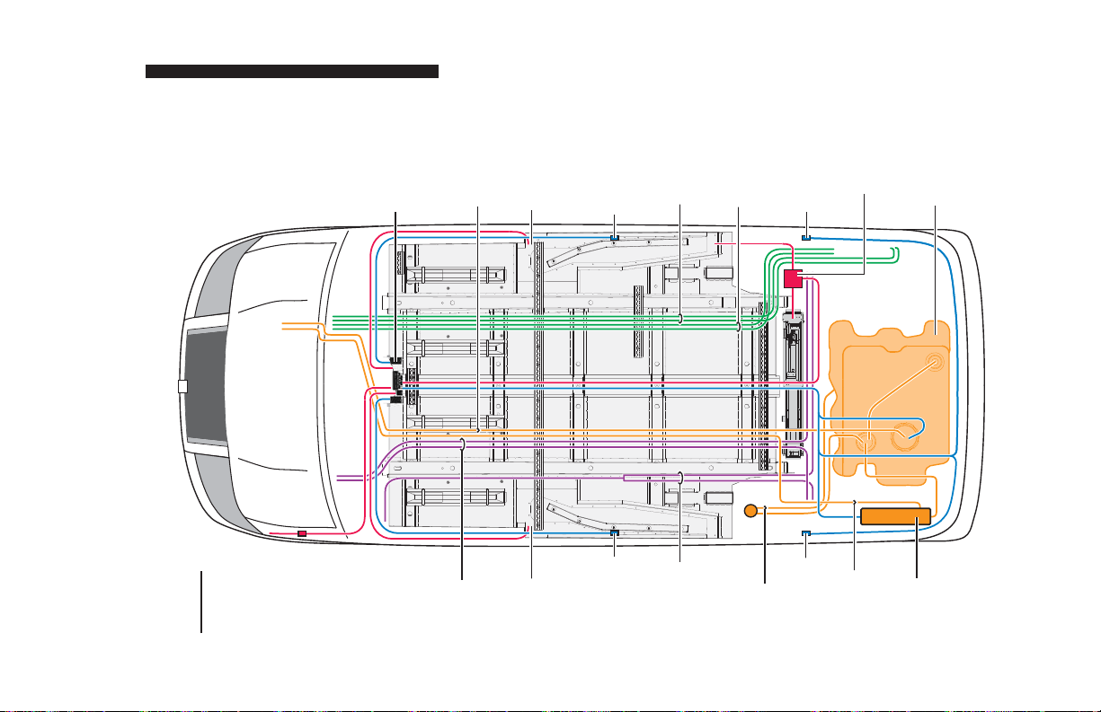
Q(p)
Below Floor
Obstructions
Gateway
Electrical
Center (SIR
Gateway
Terminator,
AUXILIARY POWER SUPPLY / BELOW FLOOR OBSTRUCTIONS
Module and
Main Fuel
Fuse Block)
Line
Station
Passenger
Receptacle
Sensor
Side Impact
Lines
Rear A/C
Lines
Rear Heat
Braun
Sensor
Side Impact
Controller
Tank
OEM Fuel
Color Key
OEM Wiring
Fuel System
Braun Wiring
Brake System
Heat & A/C
Lines
Brake
Driver
Station
Receptacle
Sensor
Side Impact
Emergency
Brake Cables
Tube
Fuel Fill
Sensor
Charcoal
Side Impact
OEM
Vapor Line
Canister
Charcoal
Page 55
Page 58

JACKING AND TIRE CHANGING INSTRUCTIONS
Jacking and Tire Changing
Interior Spare Tire Mount: The spare tire
is located behind the rear bench seat in the
passenger side floor compartment. The
OEM jack, jack handle and winch handle
tools are stored inside the rear diver side
wall compartment (OEM location).
Jack Points: Front and rear wheel jacking
points have been repositioned during conversion procedures. The modified vehicle
jack points are depicted in the illustration at
right.
Jacking and Tire Changing Procedures:
Jacking and tire changing procedures have
not been affected by the conversion. If the
rear of the vehicle is in the kneeled position,
raise the rear of the vehicle to normal position before jacking. Detailed tire changing
instructions are provided in the OEM-supplied owner’s manual.
Refer to the OEM-supplied manual for tire
changing instructions and safety precautions,
as well as instructions regarding other roadside emergencies.
Jack
Points
Page 56
Page 59

REPORTING SAFETY DEFECTS
Reporting Safety Defects to the
United States Government
If you believe that your vehicle has a defect which could
cause a crash or could cause injury or death, you should
immediately inform the National Highway Traffic Safety
Administration (NHTSA) in addition to notifying the Braun
Corporation.
If NHTSA receives similar complaints, it may open an investigation, and if it finds that a safety defect exists in a group of
vehicles, it may order a recall and remedy campaign. However, NHTSA cannot become involved in individual problems
between you, your dealer or the Braun Corporation.
To contact NHTSA, you may either call the Auto Safety Hotline toll-free at 1-800-424-9393 (or 366-0123 in Washington,
D.C. area) or write to:
NHTSA, U.S. Department of Transportation
Washington, D.C. 20590
You can also obtain other information about motor
vehicle safety from the Hotline.
Reporting Safety Defects to The
Braun Corporation
In addition to notifying NHTSA we certainly
hope you will notify us. Please call us at
1-800-THE-LIFT
®
, or write:
The Braun Corporation
631 West 11th Street
P.O. Box 310
Winamac, IN 46996 USA
Page 57
Page 60

TOWING
Towing with a Entervan
Use of this lowered floor conversion
vehicle for towing is prohibited.
If your Entervan Needs Towed
If case of service, The Braun
Corporation recommends that this
lowered floor conversion vehicle be
transported on a trailer rather than
towed with one set of wheels suspended and the other set of wheels
remaining in road contact.
Page 58
Page 61

"Providing Access to the World"
®
Over 300 Braun
Dealers Worldwide
Page 62

34443
March 2008
Patent #6,825,628 B2
 Loading...