

braude TANKMASTER MP, TANKMASTER MP TKMP16 Installation, Operation And Maintenance Instructions
Page 1

IN037 Rev 6 May 2019
THERMAL PROCESS EQUIPMENT SPECIALISTS
Polaris
- Levelmaster
- Thermaster
- Tankmaster
- Nautilus
- Jet Stream
- ElectroJet
- Frogspawn
- Braude Chemical Pump
LIBERTA HOUSE, SANDHURST, BERKS. ENGLAND GU47 8JR
01252 876123 Fax 01252 875281
www.braude.co.uk [email protected]
Co Reg No: 585474 VAT: GB492649406
TANKMASTER MP TYPE
Combined Temperature and Liquid Level Controller
INSTALLATION, OPERATION
AND MAINTENANCE
INSTRUCTIONS
These instructions should be carefully read and understood by all operators
before installing and commissioning the equipment. Failure to comply with
instructions could invalidate the warranty. The TANKMASTER is
manufactured from high performance materials and should give trouble free
service provided it is installed, operated and maintained in accordance with
these instructions
Models Covered:
TKMP16
TKMP23
TKMP27
TKMP28
Page 2
Page: 2
Date: 06/09/2019
IN037 Rev 6 May 2019
THERMAL PROCESS EQUIPMENT SPECIALISTS
1. Controller description
The Tankmaster MP is a microprocessor controlled temperature & liquid sensing controller
capable of controlling liquid and temperature parameters within a process.
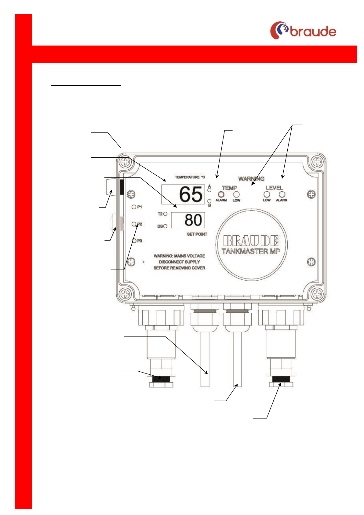
Fig 1: Tankmaster controller
Wall mounting
holes 4 corners
Calibration Pots
A & B
Control LED’s
Levelmaster / HPD probe plug
Output lead (6 wires)
230/110VAC Supply lead
Thermaster probe plug
Programming buttons
P1 – P3
Drop back push
button (if fitted)
2A slow blow fuse
5x20mm
Set point & Temp 2
display
Temp display
Page 3

Page: 3
Date: 06/09/2019
IN037 Rev 6 May 2019
THERMAL PROCESS EQUIPMENT SPECIALISTS
Additional programmable features of the controller are:a) Two independent temperature sensing circuits
b) Two independent liquid level sensing circuits
c) Variable temperature hysteresis
d) High/low temperature alarm circuit (no volt or 110/250volt output)
e) Manual energy saving function for overnight/weekend shutdown periods (not timer
operated)
f) No volt or 110/240v output relay to operate heater / pump
Please contact Braude if you require further information.
2. Warning Notice
We strongly recommend that installation is carried out by a qualified electrician. This controller
is manufactured from top quality non-corrodable materials and should give trouble free service
provided it is installed, operated and maintained properly.
Warning-Mains Voltage
Always disconnect supply before removing cover or attempting connections.
The Tankmaster MP is supplied as standard with Volt free relays UNLESS specified at
the time of order.
Should the Tankmaster MP be ordered as a mains output voltage type the grey output
lead (marked with a red warning label and fitted with a protective cap) becomes live once
the mains supply lead is connected to 230/110VAC. Always connect output lead first.
The controller is rated at 5 amps, any heater or pump likely to draw more current should
be connected through a contactor as shown in the wiring diagrams Fig 3 or 4.
Note: Failure to connect the earth may result in a serious safety hazard.
Your Tankmaster controller is sealed to IP65 standard. If the cover is removed ensure
that the gasket is firmly seated in the locating groove before tightening the remaining
screws.
Caution The controller must be isolated from the electrical supply during installation.
3. Mounting
Remove the clear plastic cover by undoing the 4 plastic screws at the corners. The controller
should be fixed to a suitable surface within reach of the probe leads using suitable screws
through the 4 fixing holes in the corner pillars. The unit should be positioned within easy reach
of the equipment to which it will be connected.
Page 4
Page: 4
Date: 06/09/2019
IN037 Rev 6 May 2019
THERMAL PROCESS EQUIPMENT SPECIALISTS
4. Electrical Connection
The controller is fitted with flying leads for easy connection. The output lead is grey in colour
and marked with a red warning label. The other lead is the mains supply. See Fig.1
4.1 Power Supplies
The Tankmaster MP is equipped with an auto sensing circuit designed to accept either
110 or 230 volt AC without the need for changing any internal parts.
4.2 Relay Operation
Your Tankmaster controller is configured for VOLT FREE operation (unless specified at
the time of order placement) and is fitted with a grey 6 wire output lead. The 6 wire
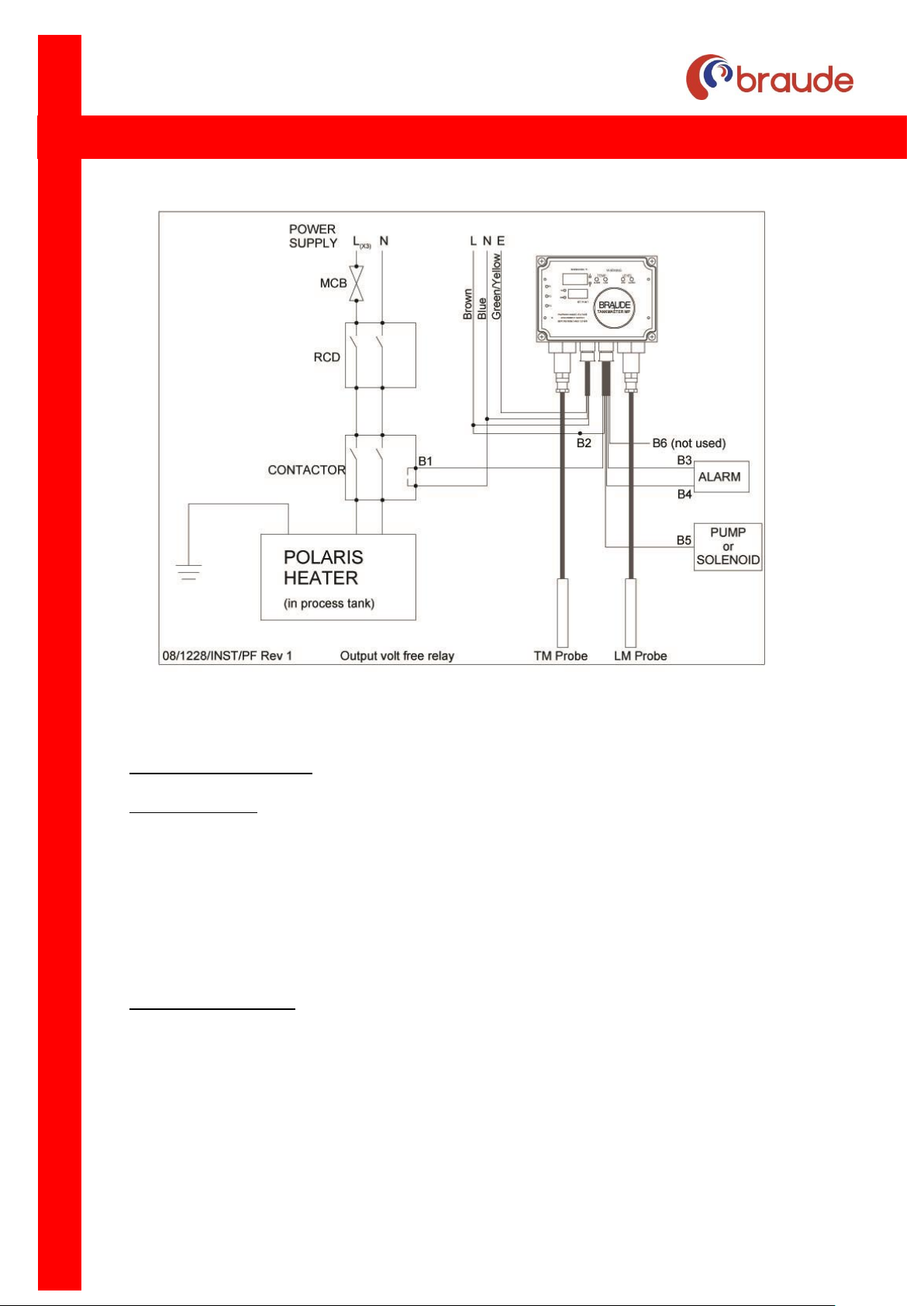
output lead connections are shown in the table below (Refer to wiring diagram Fig 4 on
page 7)
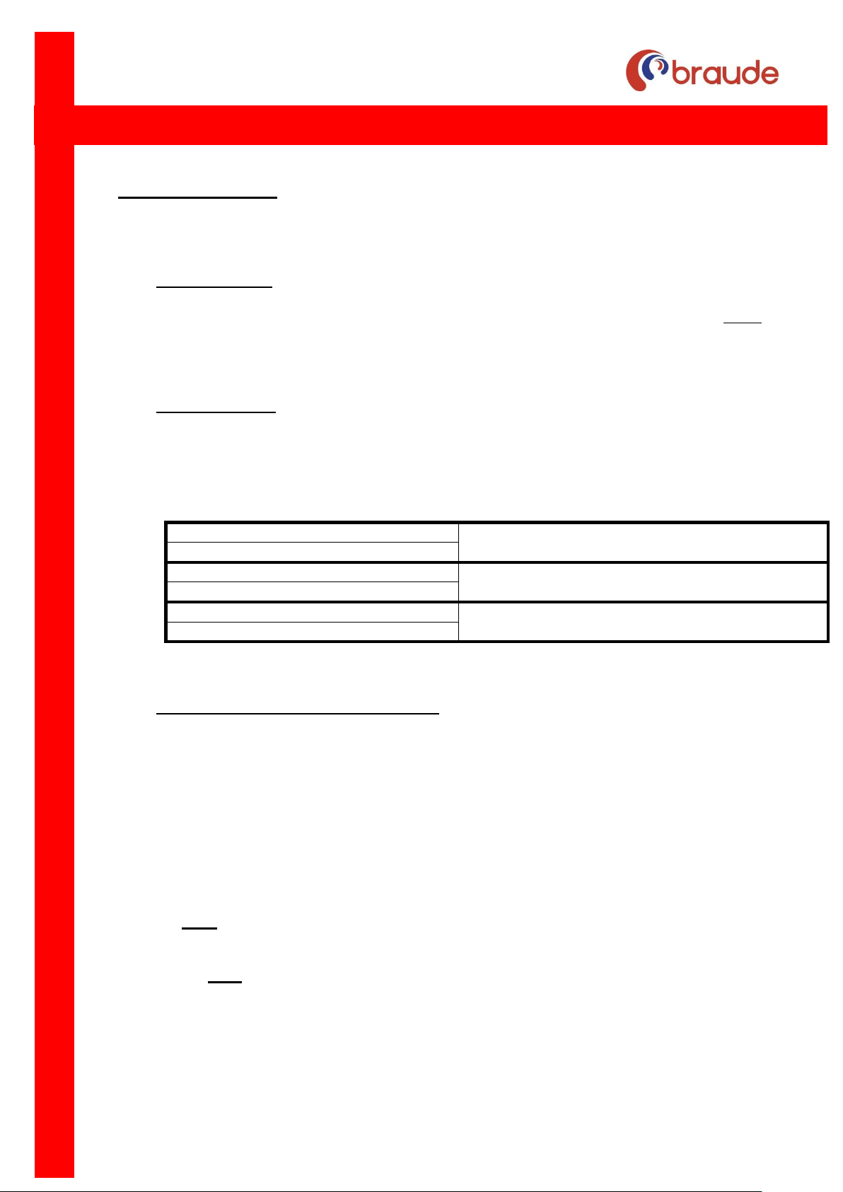
Black 1 – Heater relay output
This is a volt free relay- the output lead
connection B1/B2 is volt free
Black 2 - Heater relay common
Black 3 – Alarm relay common
This relay is volt free and any voltage between 12
and 240v may be applied across it
Black 4 – Alarm relay output
Black 5 – Level control output (pump)
This is a volt free relay – the output lead
connection B5, is volt free
Black 6 – not used (isolate)
Any suitable control voltage up to 240V may be connected to the common of the relay.
4.3 Conversion to internal mains contacts
The relay can be converted to internal mains contacts (110/240v) as follows:
a. Remove the clear cover, blue faceplate and PCB taking great care not to damage any
of the electronic components. It is advisable to earth yourself prior to carrying out this
operation. It is also recommended that this conversion be done in a clean
environment.
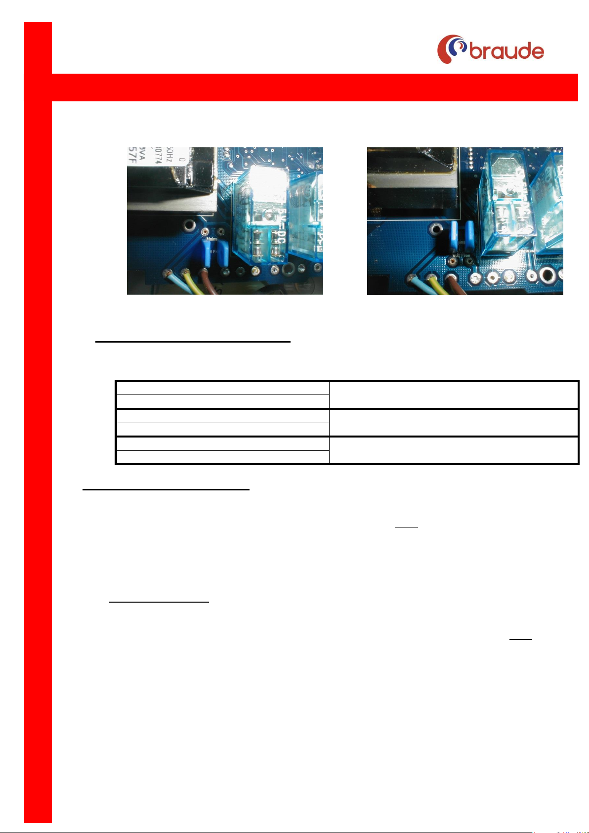
b. Locate the blue jumpers sited on the underside of the printed circuit board between
the transformer and the relay as shown in the pictures below.
c. Both jumpers should be moved to select the desired operation. The pictures below
show both configurations of jumpers.
NB both blue jumpers must be moved otherwise the PCB will be damaged.
Page 5
Page: 5
Date: 06/09/2019
IN037 Rev 6 May 2019
THERMAL PROCESS EQUIPMENT SPECIALISTS
Volt free relay Mains relay
4.4 Connections for a live relay controller
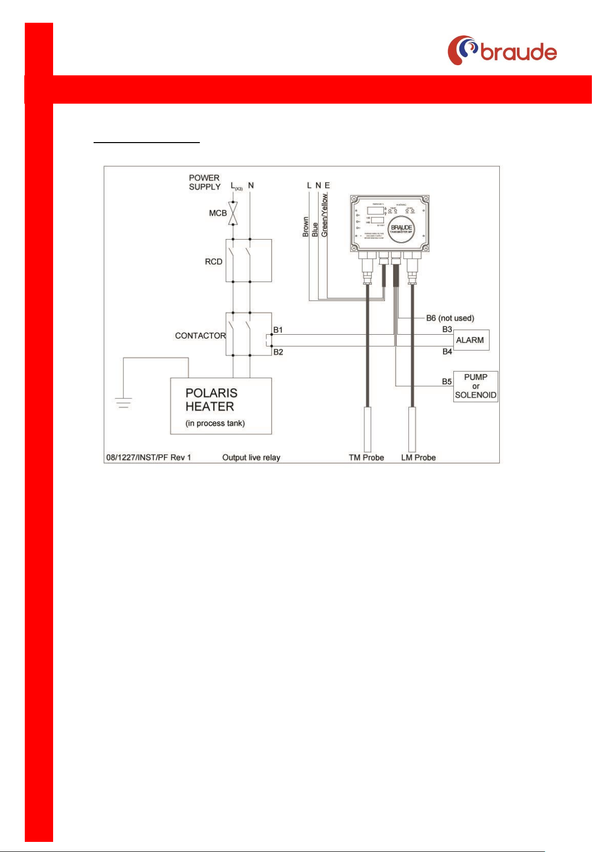
Refer to wiring diagram Fig 3 on page 7
Black 1 – Heater contactor Live
This is a live relay- the output lead connection
B1/B2 is 110/240 volts
Black 2 - Heater contactor Neutral
Black 3 – Alarm relay common
This relay is volt free and any voltage between
12 and 240v may be applied across it
Black 4 – Alarm relay output
Black 5 – Level control Live ( i.e. pump)
This is a live relay – the output lead
connection B5, is 110/240 volts
Black 6 – not used (isolate)
5. Description of controller display
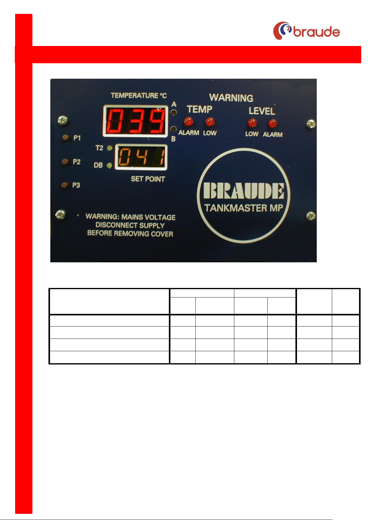
The blue faceplate, as shown in Fig 2 on page 6, has two LED displays, six LED’s and three
push buttons. The larger of the two displays, referred to as the main display throughout this
document, displays the temperature of probe T1 normally situated in the process tank. The
small LED display located below the main display is principally used to display the temperature
set point. To the right of the main display are four LED’s. These indicate the various states of
temperature and liquid level being monitored by the controller.
5.1 Temperature LED’s
The ‘Alarm’ LED indicates when the process tank temperature exceeds the UPPER
temperature limit or is below the LOWER temperature limit. This alarm light is NOT
activated on standard Tankmaster controllers.
The ‘Low’ LED indicates when the process tank temperature is BELOW the set point
temperature. This is standard on all Tankmaster controllers.
Page 6

Page: 6
Date: 06/09/2019
IN037 Rev 6 May 2019
THERMAL PROCESS EQUIPMENT SPECIALISTS
The T2 LED located to the left of the small LED display, indicates when temperature
probe T2 is showing in the small LED display. This light is NOT activated on standard
Tankmaster controllers.
The ‘DB’ drop-back LED located to the left of the small LED display indicates when the
drop-back circuit is activated. This light is NOT activated on standard Tankmaster
controllers.
5.2 Liquid Level LED’s
The ‘low’ level LED indicates when the liquid level is below the low level sensor on the
level probe. This is standard on all Tankmaster controllers
The ‘Alarm’ level LED indicates when the liquid level is above the High High or Low
sensors on the second level probe. This LED indicator is NOT activated on standard
Tankmaster controllers configured for on one level probe.
5.3 Push buttons P1 to P3
These buttons are used to configure and display the various functions of the controller.
For the standard Tankmaster controller they are used to change the SET POINT and
should be operated as follows.
5.4 Setting the SET POINT
a) Press P1 once to display the SET POINT, which is shown in the main LED display as
‘SP’. The actual set point value is shown in the small LED display window below it.
b) Press P2 to decrease the set point value or P1 to increase it.
c) Once you have selected the desired set point value press P3 once to accept it.
5.5 Setting the Hysteresis
The main LED display will now show the letters HYC meaning Hysteresis Customer
setting. This is factory set to +/- 1 degree about the set point. If you wish to keep this
value press P3 once. If you wish to change it, press P1 and P2 to adjust and then press
P3 to confirm. Both displays will revert back to normal operation.
5.6 Calibration points A and B
Two potentiometers A and B have been provided to calibrate the Tankmaster against
temperature probes attached to it. These calibration points are located to the right of the
main LED display and are marked A and B. See Fig 2.
The Tankmaster is calibrated for use with a standard temperature probes, type TPOMKV
(0.5m probe with 2m flying lead) unless specified on the despatch paperwork. Should you
attach a longer temperature probe, it will be necessary to re-calibrate the controller in
order for it to display the correct temperature. Calibration point A is for calibrating
Page 7

Page: 7
Date: 06/09/2019
IN037 Rev 6 May 2019
THERMAL PROCESS EQUIPMENT SPECIALISTS
temperature probe T1 (standard) and point B for probe T2 should your Tankmaster be
configured for a two probe system.
To calibrate the controller insert a small flat ended screwdriver into the correct hole until
it engages with the potentiometer slot below. You can now rotate the screwdriver CW and
CCW to increase or decrease the displayed temperature. It is recommended you use a
glass thermometer as a reference temperature to perform this operation as detailed
below. Also ensure that you do not apply undue pressure once you reach the end stops
on the potentiometers otherwise damage will occur
5.7 Immersion Method Against Known Temperature.
Place the probe and a thermometer in a container of ice and water and allow to settle for
approx. 5 minutes.
Adjust potentiometer A or B until the Tankmaster display reads the same as the
thermometer.
Place the thermometer and the sensor in a second container with water at an elevated
temperature of say 700C and allow to settle (5 minutes)
Adjust potentiometers A or B until the Tankmaster display reads the same as the
thermometer.
Repeat the above procedure until satisfied the display is stable. The unit is now
calibrated.
NB The above procedures are recommendations and do not constitute part of a certifiable
test. It is recommended that you contact a standard testing centre if certification is
required.
Page 8
Page: 8
Date: 06/09/2019
IN037 Rev 6 May 2019
THERMAL PROCESS EQUIPMENT SPECIALISTS
Fig .2
Temp and Liquid level status
TEMPERATURE
LEVEL
HEATER
PUMP
Alarm Low
Low
Alarm
Temperature below set point
OFF
ON
- - ON
-
Temperature above set point
OFF
OFF
- - OFF - Liquid level low
- - ON
OFF
OFF
ON
Liquid level high
- - OFF
OFF
ON
OFF
Table showing LED and heater / pump status.
Page 9
Page: 9
Date: 06/09/2019
IN037 Rev 6 May 2019
THERMAL PROCESS EQUIPMENT SPECIALISTS
6. Wiring connection
Fig 3: Wiring diagram for Tankmaster connected to Polaris heater (Live relay)
Page 10
Page: 10
Date: 06/09/2019
IN037 Rev 6 May 2019
THERMAL PROCESS EQUIPMENT SPECIALISTS
Fig 4: Wiring diagram for Tankmaster connected to Polaris heater
(Volt free relay)
7. Installation of Sensors
Probe Mounting: Position the probes at a suitable point in the tank where they will not be
damaged. The probes may be fixed using the clip provided with the black shroud above the
solution level.
The probe is supplied with a two or three pin IP66 standard plug which should be connected
to the appropriate sockets on the underside of the controller. Ensure that the locking ring is
tightened.
Double check all connections before supply is switched on.
8. Temperature Setting
Switch on the mains supply. The digital display will illuminate to indicate that power is on, the
Temp low LED will illuminate if the temperature of the solution is below set point.
Adjust the temperature Set Point to the required value as described in section 5.4 above
Page 11

Page: 11
Date: 06/09/2019
IN037 Rev 6 May 2019
THERMAL PROCESS EQUIPMENT SPECIALISTS
Once set, the Tankmaster should not require re-calibration. However, for Quality Control
purposes the unit can be re-calibrated, please contact our Technical Department.
9. Fault Display
Should a fault occur in the Thermaster temperature probe circuit, the main display will show
the following:-
Open circuit T/M probe 188
Short circuit T/M probe
Ι
17
Check connections in probe plug, secure if disconnected. Check probe and replace if there is
a short or open circuit. Controller and probe can be returned to E. Braude (London) Ltd., for
Calibration, Service and Repair.
10 Liquid Level Setting
10.1 Single level control (using 3 wire Levelmaster probe)
10.1.1 Low level only
Cut the red sensor to the low level required.
Cut the white sensor 50mm higher than the low level sensor.
Cut the green sensor to not less than 30mm below the lowest level
required.
The ends of all the sensors should be stripped to expose approximately
5mm of carbon filament.
Fit the probe assembly in clip.
10.1.2 High level only
Cut the white sensor to the high level required.
Cut the red sensor to 50mm below the high level.
The ends of all the sensors should be stripped to expose approximately
5mm of carbon filament.
Fit the probe assembly in clip
10.1.3 Wire B1 on the output lead will be live at high liquid level. Wire B5 on the
output lead will be live at low level, off at high level.
ALWAYS INSULATE AND ISOLATE ANY WIRE NOT IN USE
10.1.4 Power to the LED displays indicates main supply present. The level low LED
indicates solution level below the red sensor.
Page 12

Page: 12
Date: 06/09/2019
IN037 Rev 6 May 2019
THERMAL PROCESS EQUIPMENT SPECIALISTS
10.2 Dual level control (using 3 wire levelmaster probe)
10.2.1 Level Setting
Cut the white sensor to the high level required.
Cut the red sensor to the low level require
Cut the green sensor to not less than 30mm below the lowest level
required.
The ends of all the sensors should be stripped to expose approximately
5mm of carbon filament.
Fit the probe assembly in clip.
10.2.2 Connect the wire B1 to the heater contactor and wire B5 to the pump contactor
(if required). Wire B2 is a neutral for both.
10.2.3 Power to the LED displays indicates main supply present. The level low LED
indicates solution level below the red sensor.
10.3 Level control using polaris heater HPD probe (applies to TKMP27 and TKMP28)
INSTALLATION
Mount the POLARIS in the tank following the relevant installation instructions, supplied
with your immersion heater. If the HPD is used to control more than one heater, the
POLARIS fitted with an HPD probe must be mounted slightly higher than the others.
Plug the probe lead into the right hand side of the Tankmaster controller and screw the
locking ring firmly home. The level warning light will come on when the solution level falls
below the HPD probe which is located at the top of the POLARIS.
Connect wire B1 on the output lead to the contactor for the heater. Wire B5 will be live
under low level conditions and could be used to power a remote alarm, otherwise it should
be isolated.
OPERATION
The level control is fully automatic and does not require attention once installed.
However, it is recommended that the HPD probe in the POLARIS is cleaned as part of
the regular maintenance schedule set out in the POLARIS installation instructions.
For de-ionised water and similar low conductivity solutions a special high sensitivity
controller is supplied with stainless steel sensors. These are marked as follows:
White - high level
Red - low level
Green - common
Page 13

Page: 13
Date: 06/09/2019
IN037 Rev 6 May 2019
THERMAL PROCESS EQUIPMENT SPECIALISTS
During commissioning of the standard units, if tap water is used for testing add a small
amount of common salt to increase the conductivity of the solution.
It is recommended that the probe assemblies are cleaned as part of the regular
maintenance schedule to avoid build up of scale or other solids.
E. BRAUDE (LONDON) LTD
LIBERTA HOUSE, SANDHURST, BERKS. ENGLAND GU47 8JR
01252 876123
Fax 01252 875281
www.braude.co.uk
 Loading...