

Page 1
Solera
Owner's Manual
Keep these instructions for future reference.
Specifications subject to change without notice.
Printed in the U.S.A. (August 2009) BSI, LLC
www.brasssmith.com 5125 Race Court Denver, Colorado 80216 Office: 303.331.8777 Fax: 303.331.8444
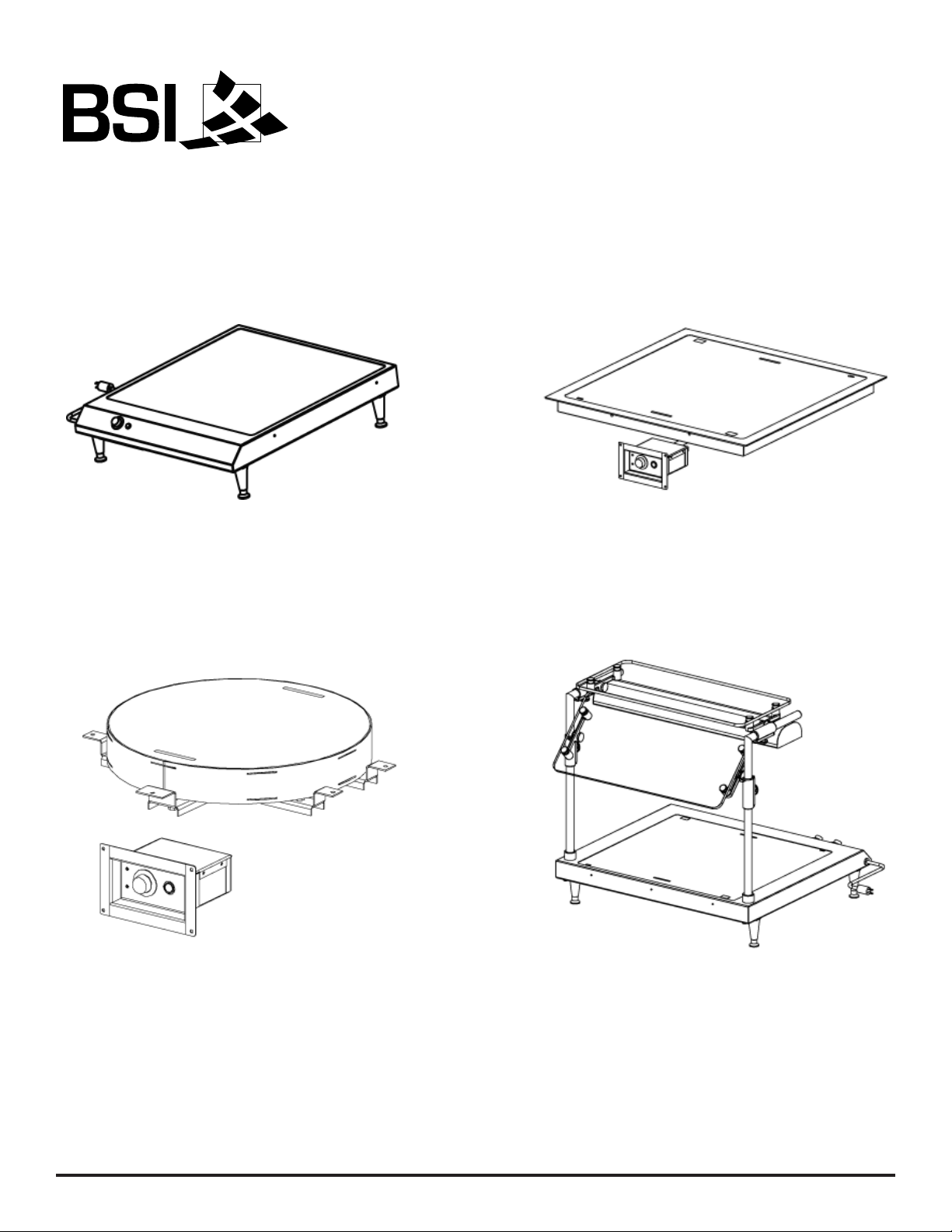
HTD: Drop-in Heated Display
HTC: Counter Heated Display
HDD: Round Drop-in Heated Display
HTZ: Counter Heated Display w/ZGuard &
Heat/Light Combo
Page 2
Specifications subject to change without notice.
Printed in the U.S.A. (August 2009) BSI, LLC
www.brasssmith.com 5125 Race Court Denver, Colorado 80216 Office: 303.331.8777 Fax: 303.331.8444
Description of Operation
This unit is designed as a food display that temperarily slows the cooling of already cooked
food, not a food re-thermalizer. This unit is not designed to reheat or cook food.
Limitations
The unit is only to be used for displaying pre-cooked food. The unit cannot be used as a display
for uncooked food.
This unit is not an oven or cook top and will not complete the cooking process of partially
cooked food.
Food is required to be pre-cooked/pre-heated to a minimum temperature of 140°F before being
placed on the unit.
If the unit’s surface temperature is less than 160°F, it will not hold the food temperature at
140°F.
Disclaimer
The unit supplied is designed to hold a number of food containers. If the containers are stacked
on top of one another, the top containers may not hold the temperature of 140°F.
To reduce the risk of electric shock, do not remove or open cover. No user-serviceable parts
inside. Refer servicing to qualified personnel.
Features
The unit has an infinite controller to control the surface temperature of the heated base.
Warning
To prevent electrical shock that can cause severe
personal injury or death, this unit must be properly
grounded. Electrical grounding instructions—This
unit is equipped with a grounding plug for protection
against possible shock hazards. Do not cut or break
off the grounding prong of the plug.
W
arning
There are hot surfaces that can cause burns. The
normal operating temperature should be between
180°F and 250°F.
Page 3

Specifications subject to change without notice.
Printed in the U.S.A. (August 2009) BSI, LLC
www.brasssmith.com 5125 Race Court Denver, Colorado 80216 Office: 303.331.8777 Fax: 303.331.8444
Warning: Connection of this equipment to electrical power other than that
specified may result in severe damage to the unit and/or fire.
1. Remove unit from the shipping container. Be careful not to damage the unit.
2. NSF requires units over 36" in width or weighing over 80 lbs. be raised off the installation
surface with 4" legs (shipped loose). Legs screw into bottom of unit.
3. Set unit in place. Unit does not require any perimeter clearance from combustible materials.
4. Insure that the infinite controller is off before plugging unit in.
5. This unit is designed to plug into a grounded, 120 volt, 15/20-amp receptacle.
6. Plug unit into appropriate receptacle.
7. Turn the unit on and set the controller to "4". Check the function of all features.
Counter-Top Units Installation Instructions (HTC & HTZ)
Installation Instructions
Additional HTZ Installation Instructions - 48" Models and Larger Only
This product has two power supply cords. Connect each plug to a receptacle that is connected to
an individual branch circuit. Unplug both cords before moving or servicing this unit. Do not unplug
only one during movement, testing, or repair of the product.
Page 4

Specifications subject to change without notice.
Printed in the U.S.A. (August 2009) BSI, LLC
www.brasssmith.com 5125 Race Court Denver, Colorado 80216 Office: 303.331.8777 Fax: 303.331.8444
Installation Instructions (continued)
Drop-In Units Installation Instructions (HTD & HDD)
1. Remove unit from the shipping container. Be careful not to damage the unit.
2. Cut opening into counter top per drawings.
3. There is a minimum of 6" bottom clearance required.
For HTD No Flange and HDD No Flange:
Mount frame bracket to the underside of the counter with screws provided.
Drop remote control housing through cut out and mounting frame.
Position unit in cut out.
Level unit. Keep flush with counter top surface by using leveling screws in
mounting frame.
After leveling, secure lock nut on leveling screws.
Silicone perimeter of unit between counter top and unit chassis using approved
food grade (NSF) high temp silicone.
4. Set unit in place.
5. Cut counter apron for remote control housing per dimensions on print provided. Drill mounting
holes using the front cover as template for hole pattern.
6. Secure remote control housing front cover in cut out in apron.
7. Secure remote control housing to front cover with screws provided.
8. Insure that the infinite controller is off before plugging unit in.
9. Turn the unit on and set the controller to "4". Check the function of all features.
Page 5

Specifications subject to change without notice.
Printed in the U.S.A. (August 2009) BSI, LLC
www.brasssmith.com 5125 Race Court Denver, Colorado 80216 Office: 303.331.8777 Fax: 303.331.8444
Proper Use
Once the unit is installed. Turn the infinite controller to “4”. After the controller is set to “4” the
unit will need approximately 1/2 hour to reach the proper operating temperature.
After the unit has been on for 1/2 hour, it is ready to hold the pre-heated/pre-cooked food.
The food to be placed on the unit must already be at 140°F minimum.
The controller can be adjusted (180°F-250°F) by turning the knob to a higher or lower setting.
"8" being the highest temperature and "1" being the lowest.
Cleaning Instructions
Caution: Unplug power to the unit before cleaning.
The recommended cleaner for the exterior of the unit is Cerma Bryte®. DO NOT use an
abrasive cleaner; it will scratch the surface and detract from its appearance.
Do not use excessive amounts of water when cleaning, as damage to electrical components
could result.
Do not immerse unit in water.
Troubleshooting
W
arning: Serious injury or death can occur if an unqualified person attempts
to service this unit.
If the unit does not reach operating temperature:
1. Please contact BSI, LLC (1.800.662.9595).
If the unit exceeds the normal operating temperature:
1. Please contact BSI, LLC (1.800.662.9595).
If the lighted switches do not light up when flipped to the on position:
1. Check that the unit is plugged into a properly operating receptacle.
2. Please contact BSI, LLC (1.800.662.9595).
Operating Instructions
Page 6
Specifications subject to change without notice.
Printed in the U.S.A. (August 2009) BSI, LLC
www.brasssmith.com 5125 Race Court Denver, Colorado 80216 Office: 303.331.8777 Fax: 303.331.8444
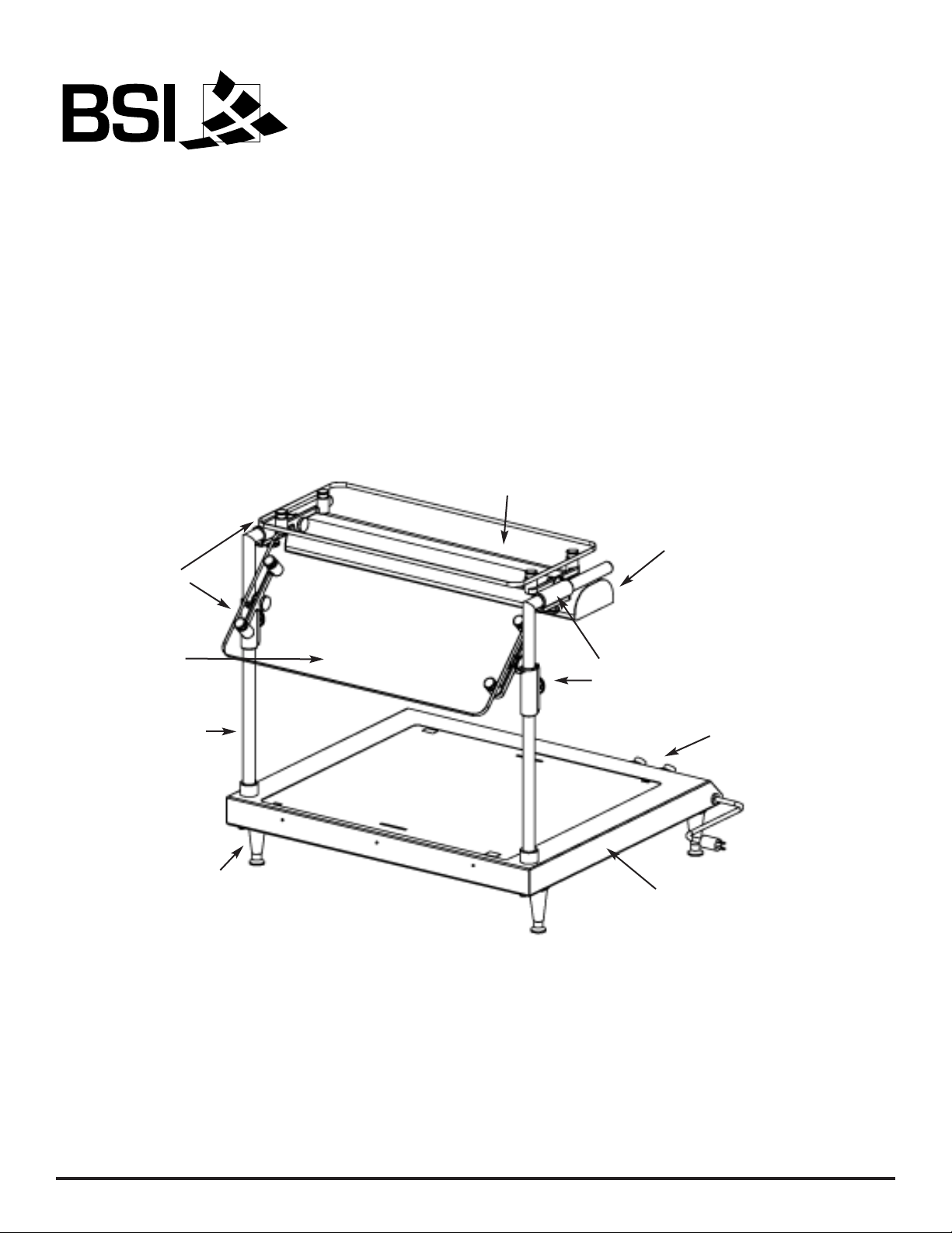
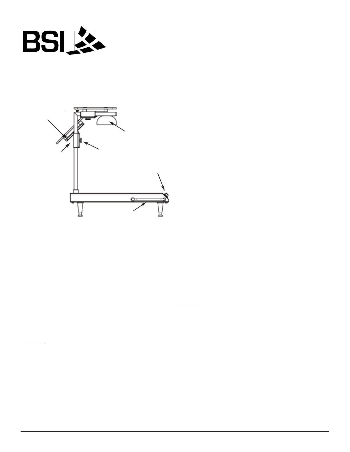
Glass Panel
Glass Top Shelf
Right Bracket
Left Bracket
4" Leg
Infinite Control
1" Post
Heat/Light Combo
Counter-Top Solera Unit
HTZ Components
Page 7
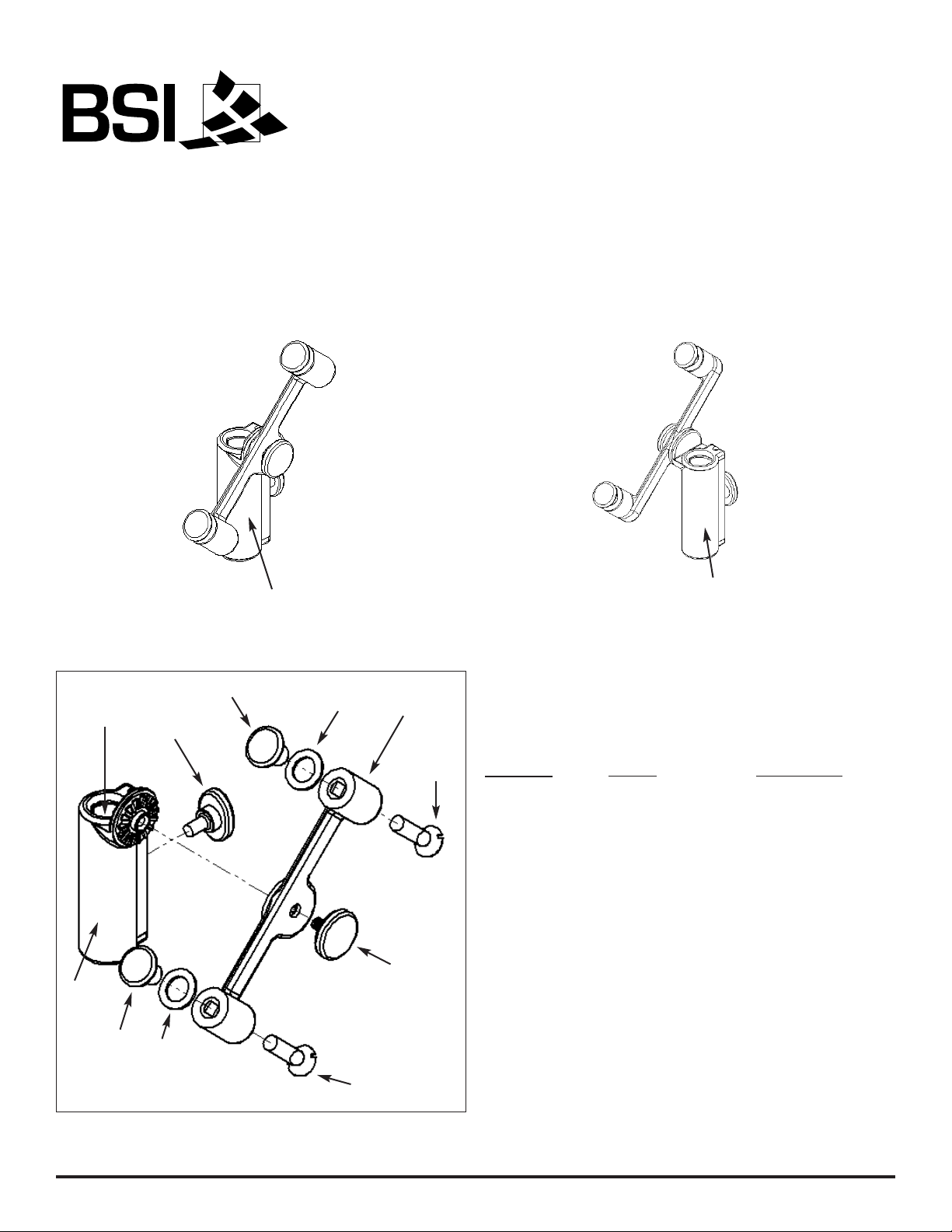
Left Post Clamp
Part #322
Right Post Clamp
Part #323
Specifications subject to change without notice.
Printed in the U.S.A. (August 2009) BSI, LLC
www.brasssmith.com 5125 Race Court Denver, Colorado 80216 Office: 303.331.8777 Fax: 303.331.8444
Fig. 1: Left Bracket Fig. 2: Right Bracket
Fig. 3: Left Bracket Exploded
A
B
C
D
E
F
G
H
G
E
H
ZGuard: Bracket Parts
Location
Part # Part Name
A ............ 321 ............. Glass Mounting Clamp
B ............ See Fig. 1, 2 Post Clamp
C ............ 324 ............. Post Clamp Insert
D ............ 326 ............. Round Knob
E ............ 336 ............. Decorative Nut
F ............ 457 ............. Oval Knob
G ............ 484 ............. Spacer
H ............ Included ...... Screws
Page 8
Specifications subject to change without notice.
Printed in the U.S.A. (August 2009) BSI, LLC
www.brasssmith.com 5125 Race Court Denver, Colorado 80216 Office: 303.331.8777 Fax: 303.331.8444
The angle of the glass panels can be tilted forward
or backwards. The brackets can be raised or
lowered. As detailed in Fig. 4, the bracket's Oval
Knob is on the Server Side. The bracket's Round
Knob, which holds the Glass Mounting Clamp in
place, faces the food.
Glass Angle (Tilt)
Glass & Bracket Position
To properly adjust the angle of the glass it may be
helpful for there to be one person for every
bracket.
Glass is shipped in the vertical position at its
lowest height. Before adjusting glass be sure shield
is properly mounted to counter, wall or ceiling.
Glass angle is controlled by the Round Knob
located on the bracket. To change the angle of the
glass firmly hold the glass in one hand while
turning the knob in a counter-clockwise direction to
loosen.
Caution:
Too many revolutions will cause the knob
to fall out and the glass susceptible to separation
from the bracket.
Once loosened on both sides, tilt glass to desired
angle, then properly tighten knobs in clockwise
direction.
Use a level to properly balance the full length of
the glass.
To properly adjust the height of the glass it may be
helpful for there to be one person for every
bracket.
With glass at desired angle, loosen (counterclockwise direction) Oval Knobs on the back of the
brackets.
Caution:
Too many revolutions will cause the knob
to fall out and the bracket susceptible to sliding
down the length of the post.
Once knobs are loosened on both sides, raise the
glass to desired height, then tighten knobs in
clockwise direction.
Use a level to properly balance the full length of
the glass.
Glass Height
Top shelf is not adjustable.
Top Shelf
Server Side
Customer Side
Right Bracket
Oval Knob
Glass Mounting
Clamp
Heat/Light Combo
Fig. 4: HTZ Side View
Infinite
Control
Cord
Page 9

Specifications subject to change without notice.
Printed in the U.S.A. (August 2009) BSI, LLC
www.brasssmith.com 5125 Race Court Denver, Colorado 80216 Office: 303.331.8777 Fax: 303.331.8444
Recommended Limitations
Weight Limits
Recommendation
ZGuard food shield systems that are equipped with
a shelf are not intended to withstand heavy
weights. Glass shelves can certainly hold small
display items.
Do not exceed 75 lbs. total weight of all display
items across a three foot panel of 3/8" glass.
Cleaning Instructions
DO
• Do wipe the surface with a clean damp cloth to
remove fingerprints, dust, etc.
• Do spray with a light coating of glass cleaner to
remove grease or other dirt. Use a non-ammonia
cleaner.
DON’T
• Don't polish ZGuard with any brass polish. Your
ZGuard has a durable finish and will maintain its
finish for years if well maintained. (Polishing the
finish with a polishing agent of any kind will
destroy the coating).
• Don't scrub the surface with any abrasive
substance such as steel wool, pot scrubbers, Ajax
cleanser, Comet or similar products, as it will
remove the protective coating.
Ordering
Replacement Parts
In case of damaged parts please call our Customer
Service Department at 1-800-662-9595.
If you have any other maintenance
questions concerning ZGuard,
please contact our
Customer Service Department
Monday thru Friday
8:00am to 4:30pm MST at
1-800-662-9595
Page 10
Specifications subject to change without notice.
Printed in the U.S.A. (August 2009) BSI, LLC
www.brasssmith.com 5125 Race Court Denver, Colorado 80216 Office: 303.331.8777 Fax: 303.331.8444
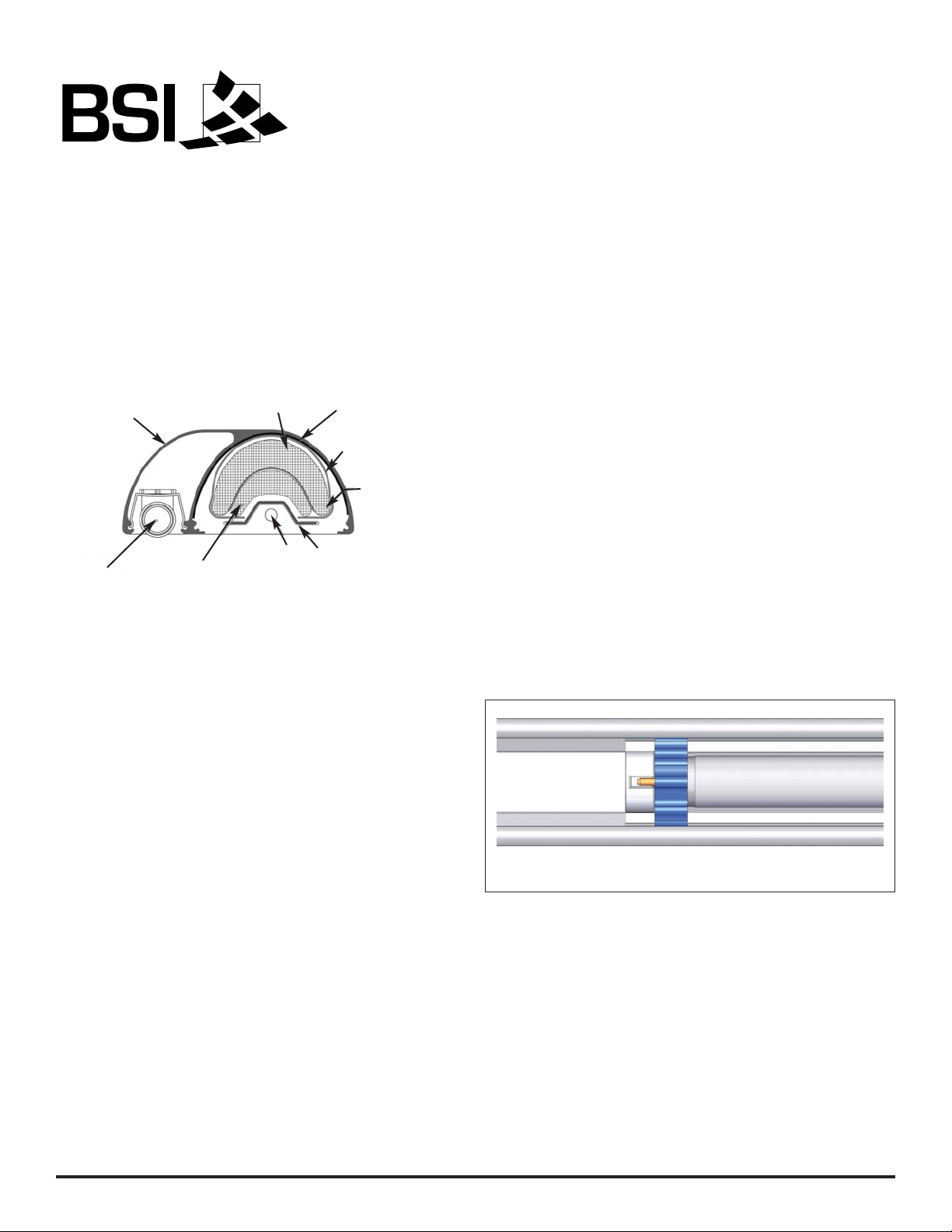
HTZ's Heat/Light Combo
Components
Cleaning Instructions
DO
• Do turn the power to the light or warmer off
before cleaning.
• Do wipe the surface with a clean damp cloth to
remove fingerprints, dust, etc.
• Do spray with a light coating of glass cleaner to
remove grease or other dirt. Use a non-ammonia
cleaner.
DON’T
• Don't leave the power on when cleaning.
• Don't spray any cleaning product directly into the
bulbs, fixtures or heating elements.
Replacing the Fluorescent Light Bulbs
When a fluorescent bulb burns out and needs to be
replaced you will need to do the following:
• Turn off power to all lights and warmers.
• Carefully turn the bulb 90o in either direction to
unlock it from the white lamp holders at each end.
• Once unlocked, the pins will be visible through
the open slots at each end. Caution: At this
position bulbs are free to fall down through open
slots.
• If the bulb does not easily slid out from the
holders, then carefully use needle-nose pliers to
grab the bulb, evenly pulling it down and out.
• With the new bulb in hand, evenly push the pins
up into the open slots of the lamp holders.
• Carefully turn the bulb 90
o
in either direction to
lock it into the white lamp holders at each end.
Fig. 6: Slimline Light Section (T5 Bulb)
BSI uses only T5 size bulbs. New light bulbs can
be ordered from Grainger. Please call them direct
at 1.888.361.8649 or visit their website at
www.grainger.com.
Ordering New Bulbs
Fig. 5: Heat/Light Combo Section View
Housing
Inner Reflector
Light
Housing Reflector
Thermal Wrap
Inner
Insulation
Main Reflector
Element
Outer Insulation
Page 11

Specifications subject to change without notice.
Printed in the U.S.A. (August 2009) BSI, LLC
www.brasssmith.com 5125 Race Court Denver, Colorado 80216 Office: 303.331.8777 Fax: 303.331.8444
Kevry Corporation warrants that its fabricated products shall be free from any defects in material and
workmanship for a period of one year from date of shipment.
Kevry guarantees parts furnished by suppliers to Kevry only to the extent of the original manufacturer’s
express warranty to Kevry. Failure of the Original Purchaser to receive such manufacturer’s warranty
shall in no way create any warranty, express or implied, or any other obligation or liability on Kevry’s
part in respects thereof.
If shipment of a replacement part is requested prior to the arrival in the Kevry factory of the part
claimed to be defective, the Original Purchaser must accept delivery of the replacement part on a
C.O.D. basis, with credit being issued after the part has been received and inspected at Kevry’s plant
and determined by Kevry to be within this Warranty.
No claims can be made under this Warranty for spoilage of products for any reason, including system
failure.
Warranty work not performed by Kevry Corporation personnel must have prior written authorization.
Kevry can decide to approve on site repairs, providing at no charge new replacement parts and also
paying reasonable labor charges for a period of 90 days from date of shipment. A Return Material
Authorization number to be accepted must accompany returned goods.
This warranty does not apply to:
Buyouts or purchased components, including but not limited to, faucets and drains as these are
covered by the original manufacturers’ warranties,
Freight damaged material,
Damage caused by improper installation, improper use, or abuse, or equipment modified without
factory authorization,
Damaged caused by normal wear and tear,
Control adjustment, timer setting, thermometer calibration, and refrigeration items not installed in
the factory by Kevry.
Customer furnished materials or buyouts.
This warranty is the complete and only warranty, expressed or implied. Kevry Corporation Inc.’s liability
is limited to the purchase price of the equipment. The customer’s sole and exclusive remedy is the
repair, replacement, or refund for the defective equipment.
Limited Warranty - Standard Equipment Warranty
Page 12

Specifications subject to change without notice.
Printed in the U.S.A. (August 2009) BSI, LLC
www.brasssmith.com 5125 Race Court Denver, Colorado 80216 Office: 303.331.8777 Fax: 303.331.8444
BSI, LLC Warranty
BSI, LLC warrants its new products to be free from defects in material and workmanship from the date of
their original purchase for normal use and for the applicable warranty periods set forth below. BSI, LLC’s
warranty extends only to original purchasers acquiring new products purchased in the United States
directly from BSI, LLC, its authorized dealers or other companies specifically authorized by BSI, LLC to
act as resellers of its products.
ZGUARD
BSI, LLC warrants the ZGuard system against defects in material and workmanship for a period of one
year from invoice date. This excludes glass chipping or breakage after installation that can be explained
as “use and abuse”.
STEALTH WARMERS and LIGHTS
BSI, LLC warrants the Stealth Warmer against defects in material and workmanship for a period of one
year from invoice date. The warming element is warranted for two years from invoice date.
THERE ARE NO WARRANTIES EXCEPT AS EXPRESSLY STATED ABOVE WHETHER EXPRESSED
OR IMPLIED, INCLUDING BUT NOT LIMITED TO ANY WARRANTY OF MERCHANTABILITY OR
FITNESS FOR ANY PARTICULAR PURPOSE. These warranties do not apply to any products which
have been altered in any way or to products which have been subject to misuse, abuse, neglect,
accident, or which have been damaged in transit. Warranty is void if products are used, held or stored in
an unsupervised environment. BSI, LLC’s liability for its products shall be limited to the repair or
replacement of products or, at BSI, LLC’s option, to refunding the purchase price. BSI, LLC will not be
liable, under any circumstances, for incidental or consequential damages (including, without limitation,
lost profits) arising in connection with the sale, use, inability to use, repair or replacement of BSI, LLC’s
products. The liability of BSI, LLC arising from any cause shall not exceed the price paid for the products.
Any claim for breach of the foregoing warranties shall be deemed waived unless submitted to BSI, LLC in
writing within 30 days of the date the alleged defect was discovered, or by reasonable inspection should
have been discovered. The merchandise must be returned to the BSI, LLC factory from which it was
purchased, freight prepaid, and will not be accepted unless prior written authorization to return the
merchandise has been issued by BSI, LLC. A copy of the original invoice must accompany the returned
merchandise to prove the date of original purchase and warranty entitlement. Any cause of action for
breach of the foregoing warranties shall be deemed waived unless brought within one year of the date of
the claim submission.
 Loading...