

Page 1

FOR INSTALLATION QUESTIONS PLEASE CONTACT A BRASS SMITH REPRESENTATIVE AT 1.800.662.9595
Installation Manual
ZGuard Mounting Options
Page 2
FOR INSTALLATION QUESTIONS PLEASE CONTACT A BRASS SMITH REPRESENTATIVE AT 1.800.662.9595
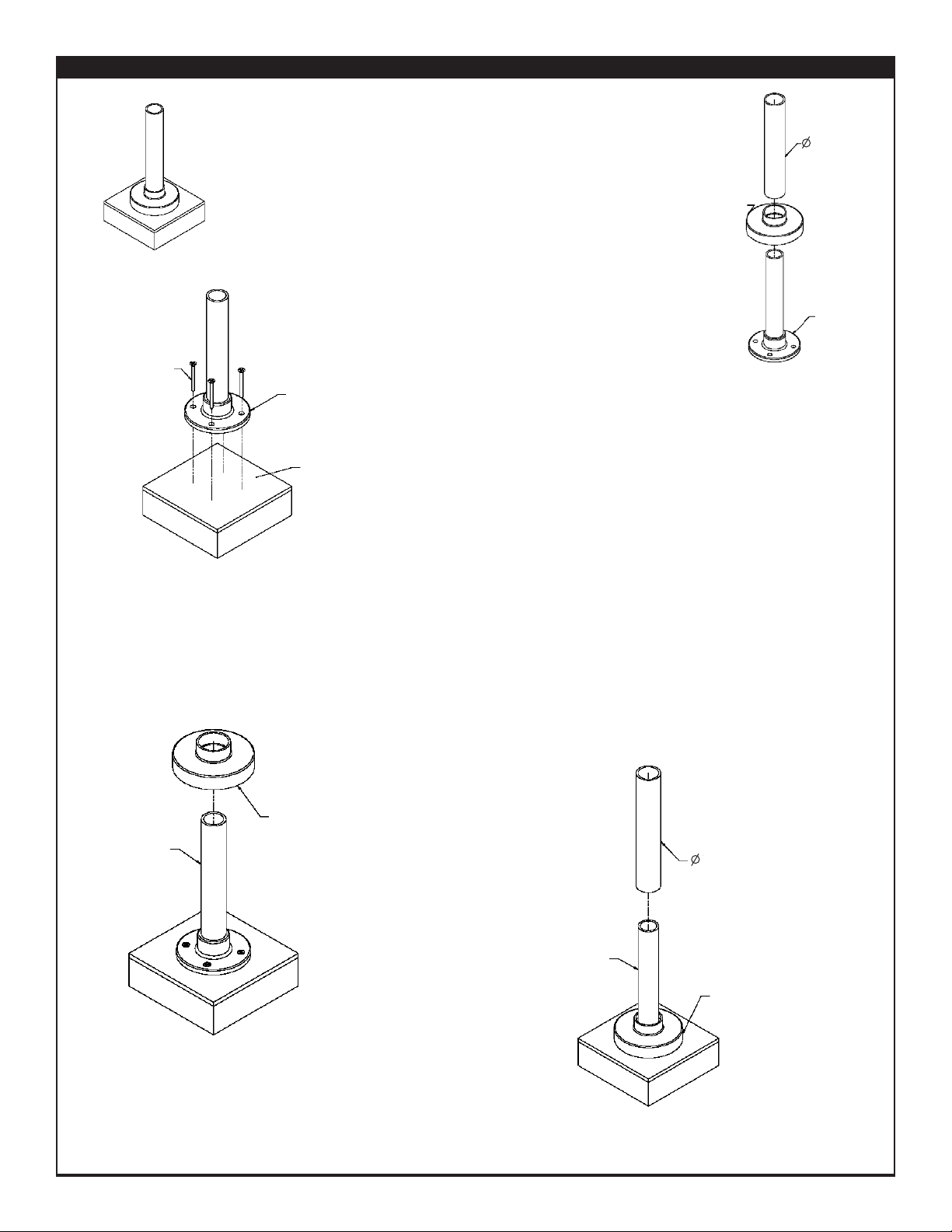
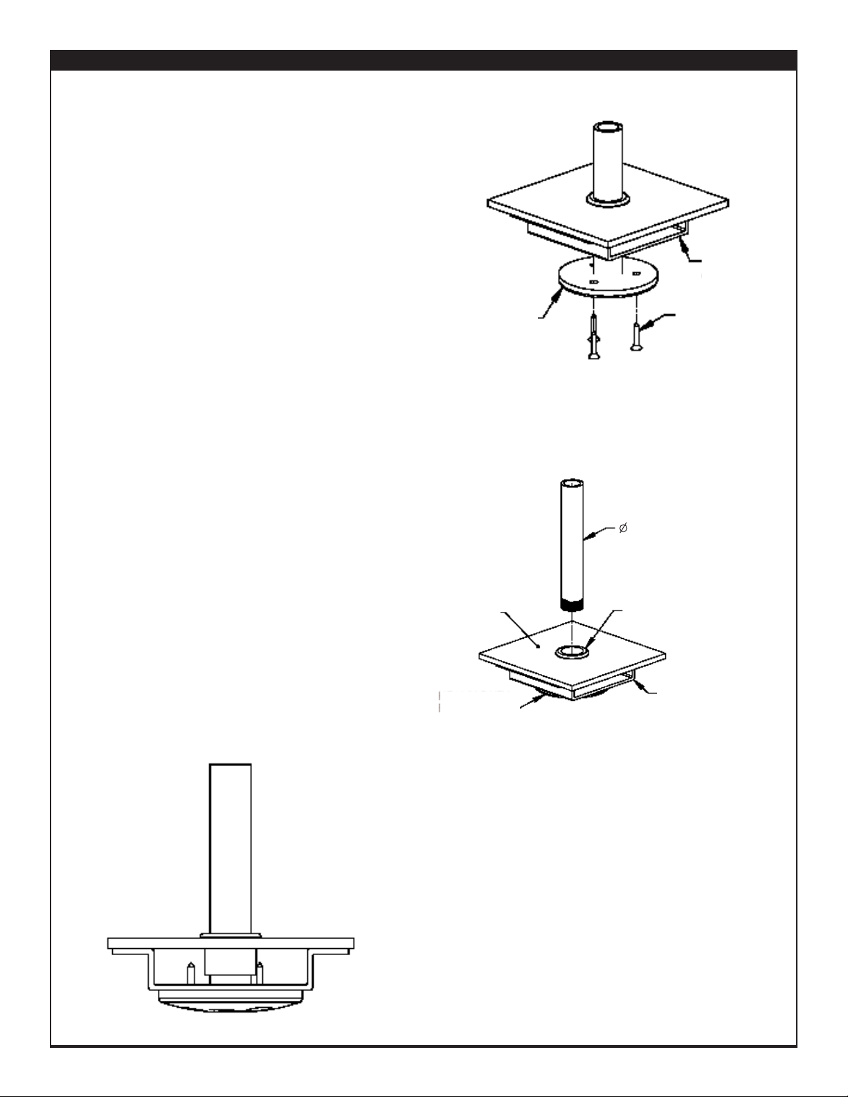
Above-Counter Heavy-Duty Flange (EZ-Span)
FIGURE 1
(Entire EZ-Span unit not shown) Lift EZ-Span unit up until
bottom of 1.5" diameter post clears internal heavy duty post
and flange and carefully set unit aside. Use care on units
with wire chase to prevent damage to wires. Also remove
decorative flange cover.
FIGURE 3
Lower decorative flange cover over steel post until it rests
seated on mounting surface centered over mounting flange.
FIGURE 4
Lift EZ-Span unit up until bottom of 1.5" diameter post clears
internal heavy duty post. If applicable, route wires down
designated wire chase post. Bottom of 1.5" diameter post
should be centered within decorative flange and sit on top of
mounting flange.
Figure 1
Figure 2
Figure 3
Figure 4
DECORATIVE
FLANGE COVER
STEEL POST &
FLANGE
1.5” POST
DECORATIVE
FLANGE COVER
STEEL POST
SCREW
STEEL POST
& FLANGE
MOUNTING
SURFACE
STEEL POST
DECORATIVE
FLANGE COVER
1.5” POST
FIGURE 2
Fasten post and flange to mounting
surface using screws provided. Tighten
securely.
Page 3
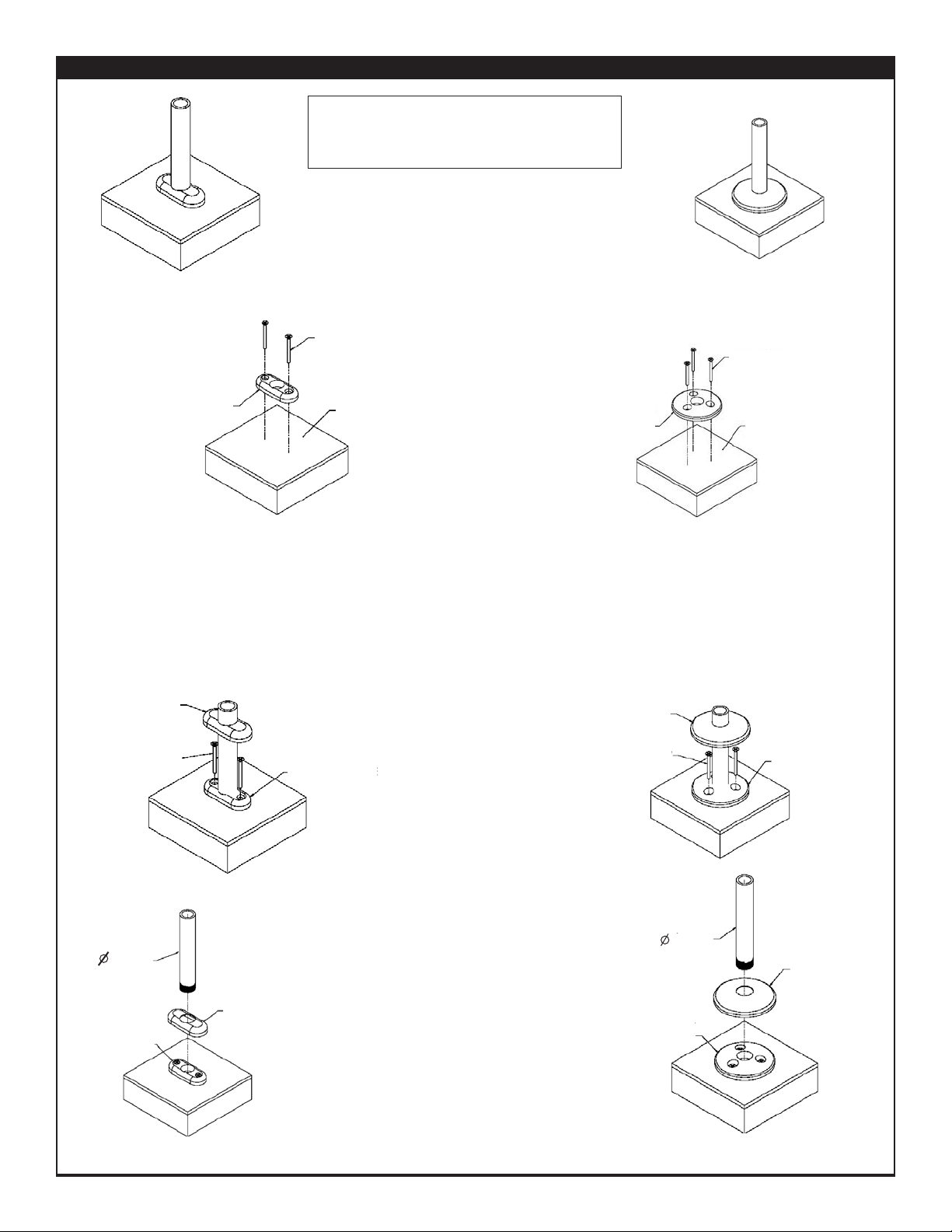
Figure 1
Above Counter Narrow - MW1(A) & Heavy-Duty Flange - MW2(B) (ZGuard)
FIGURE 1
Fasten mount flange to counter surface using
screws provided. Tighten Securely.
FIGURE 2
If unit has heat and/or lights, unit will arrive assembled. If unit has front and rear posts, leave
mount flanges on posts. In either case, place the unit in the desired position on mounting surface,
lift flange covers out of the way, and fasten attached flanges to counter using provided screws.
Lower flange cover into place over flange. For units with electrical requirements, feed wire chase
through hole in counter before lowering into position. Avoid damaging wires.
Figure 3
WOOD SCREW
MOUNTING
SURFACE
NARROW FLANGE IN
ABOVE -COUNTER
POSITION
NARROW
FLANGE COVER
MOUNTED
NARROW FLANGE
1” POST
FLANGE COVER
(LIFT OUT OF
THE WAY FOR
INSTALLATION)
NARROW FLANGE
WOOD SCREW
FIGURE 3 (Flange Cover & Post Installation)
Place flange cover over mounted flange.
Install 1" diameter post by screwing into flange.
For straight posts, tighten securely.
For cantilever posts, add provided glue to post
threads and tighten as far as possible while
keeping direction of horizontal top post in
desired direction (i.e., parallel with flange, etc).
Above-Counter Narrow Flange
Figure 2
FLANGE COVER
(LIFT OUT OF
THE WAY FOR
INSTALLATION)
HEAVY-DUTY
FLANGE
WOOD SCREW
WOOD SCREW
MOUNTING
SURFACE
Figure 3
1” POST
MOUNTED
HEAVY-DUTY
FLANGE
HEAVY-DUTY
FLANGE COVER
Determine flange mounting locations based on
centerline dimensions and, if necessary, drill
holes accordingly in mounting surface.
HEAVY-DUTY
FLANGE
IN ABOVE COUNTER POSITION
Above-Counter Heavy-Duty Flange
FOR INSTALLATION QUESTIONS PLEASE CONTACT A BRASS SMITH REPRESENTATIVE AT 1.800.662.9595
www.BSIdesigns.com 5125 Race Court Denver, CO 80216 PHONE (303) 331-8777 FAX (303) 331-8444
Page 4
FOR INSTALLATION QUESTIONS PLEASE CONTACT A BRASS SMITH REPRESENTATIVE AT 1.800.662.9595
Figure 4
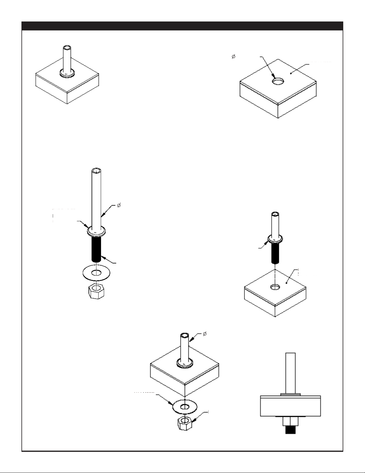
FIGURE 4
From underside of counter, install
washer and nut over threaded end of
post and tighten securely. Partial
disassembly of food shield may be
required for ease of lifting. DO NOT
REMOVE GLASS CLAMPS FROM
POSTS.
Below-Counter Compression Mount - MWU4(F)
Figure 2
Figure 3
FIGURE 3
Install post into hole in mounting surface until
threaded ring rests on counter surface. For units
with electrical requirements, feed wire chase
through hole in counter before lowering post into
position. Avoid damaging wires.
FIGURE 2
Remove nut and washer from post. Do not remove threaded
ring. Ensure threaded ring is tightened completely up
threaded portion of post.
FIGURE 1
Determine flange mounting locations based
on centerline dimensions and, if necessary,
drill holes accordingly in mounting surface.
Post hole diameter is 1.25" thru.
1.25” THRU
REMOVE NUT
AND WASHER
COUNTER
SURFACE
THREADED
RING
(TIGHTEN)
1” POST
SIDE VIEW
THREADED
RING
COUNTER
SURFACE
WASHER
NUT
1” POST
Figure 1
Below-Counter Washer-Nut Mount
Page 5
FOR INSTALLATION QUESTIONS PLEASE CONTACT A BRASS SMITH REPRESENTATIVE AT 1.800.662.9595
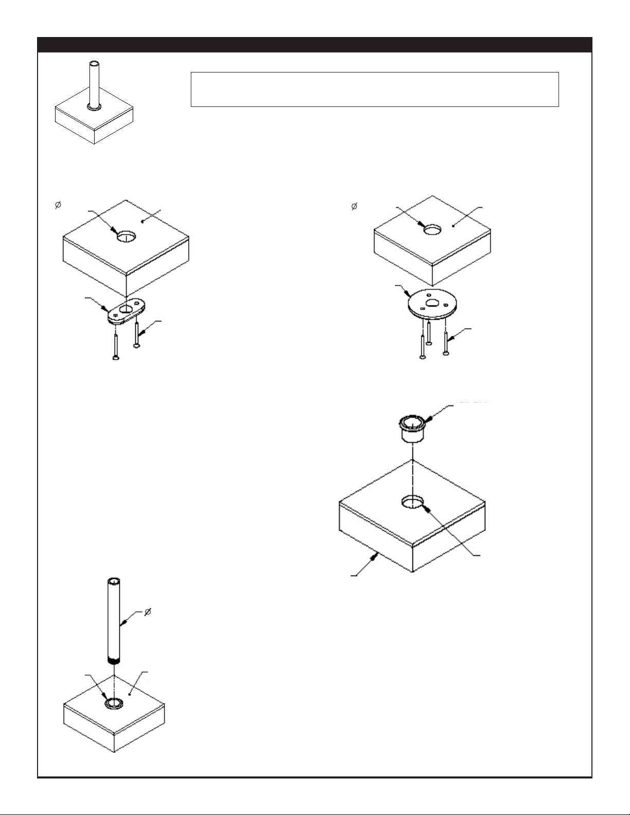
Below-Counter Narrow- MWU3(C) & Heavy-Duty Flange- MWU5(C)
FIGURE 1
Fasten mount flange to underside of counter surface using screws provided. Center
threaded hole in flange with post hole in counter. Tighten Securely.
FIGURE 2
Install grommet into post hole in mounting
surface. Press into hole in mounting surface
until completely seated.
FIGURE 3
Install post from above counter surface through grommet and securely tighten into
mounted flange.
Figure 2
Figure 3
NARROW
FLANGE
SCREW
COUNTER
SURFACE
NYLON
GROMMET
POST
HOLE
MOUNTED
FLANGE UNDER
COUNTER
1.25”
THRU
GROMMET
COUNTER
SURFACE
1” POST
Determine flange mounting locations based on centerline dimensions and, if necessary,
drill holes accordingly in mounting surface. Post hole diameter is 1.25" thru.
Figure 1
COUNTER
SURFACE
HEAVY-DUTY
FLANGE
SCREW
1.25” THRU
Below-Counter Narrow and
Heavy-Duty Flange
Page 6
FOR INSTALLATION QUESTIONS PLEASE CONTACT A BRASS SMITH REPRESENTATIVE AT 1.800.662.9595
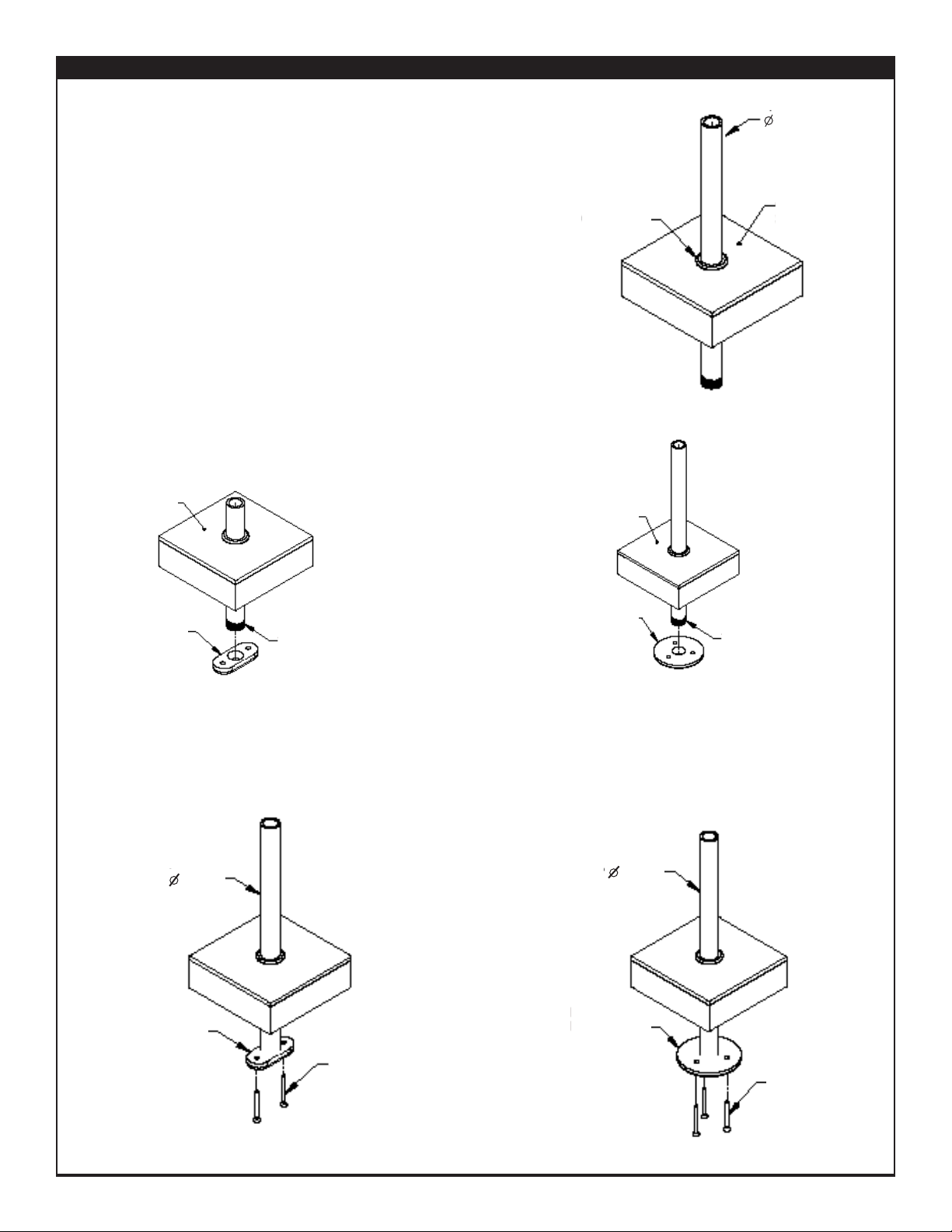
FIGURE 6
With mount flange secured to post, screw flange into underside of counter
surface as shown. Securely tighten all screws.
SCREW
HEAVY-DUTY
FLANGE
1” POST
SCREW
NARROW
FLANGE
1” POST
Figure 6
THREADED
END OF POST
NARROW
FLANGE
COUNTER
SURFACE
THREADED
END OF POST
COUNTER
SURFACE
HEAVY-DUTY
FLANGE
FIGURE 5
With post in lowered position, attach mount flange to threaded portion of
post from underside of counter surface. Tighten securely.
Figure 5
Below-Counter Narrow - MWU3(C) & Heavy-Duty Flange - MWU3(C) (Continued)
Figure 4
GROMMET
COUNTER
SURFACE
1” POST
FIGURE 4
If unit has heat and/or lights, unit will arrive assembled. For preassembled units or units with front and rear posts, remove mount
flange from post. Lower post through grommet and mounting surface.
Partial disassembly of food shield may be required for ease of lifting.
DO NOT REMOVE GLASS CLAMPS FROM POSTS. For units with
electrical requirements, feed wire chase through grommet and
mounting surface before lowering post into position. Avoid damaging
wires.
Page 7
FOR INSTALLATION QUESTIONS PLEASE CONTACT A BRASS SMITH REPRESENTATIVE AT 1.800.662.9595
Under-Counter Narrow - SSU3(E) & Heavy-Duty Flange Mount - SSU3(E) for Stainless Steel Counters
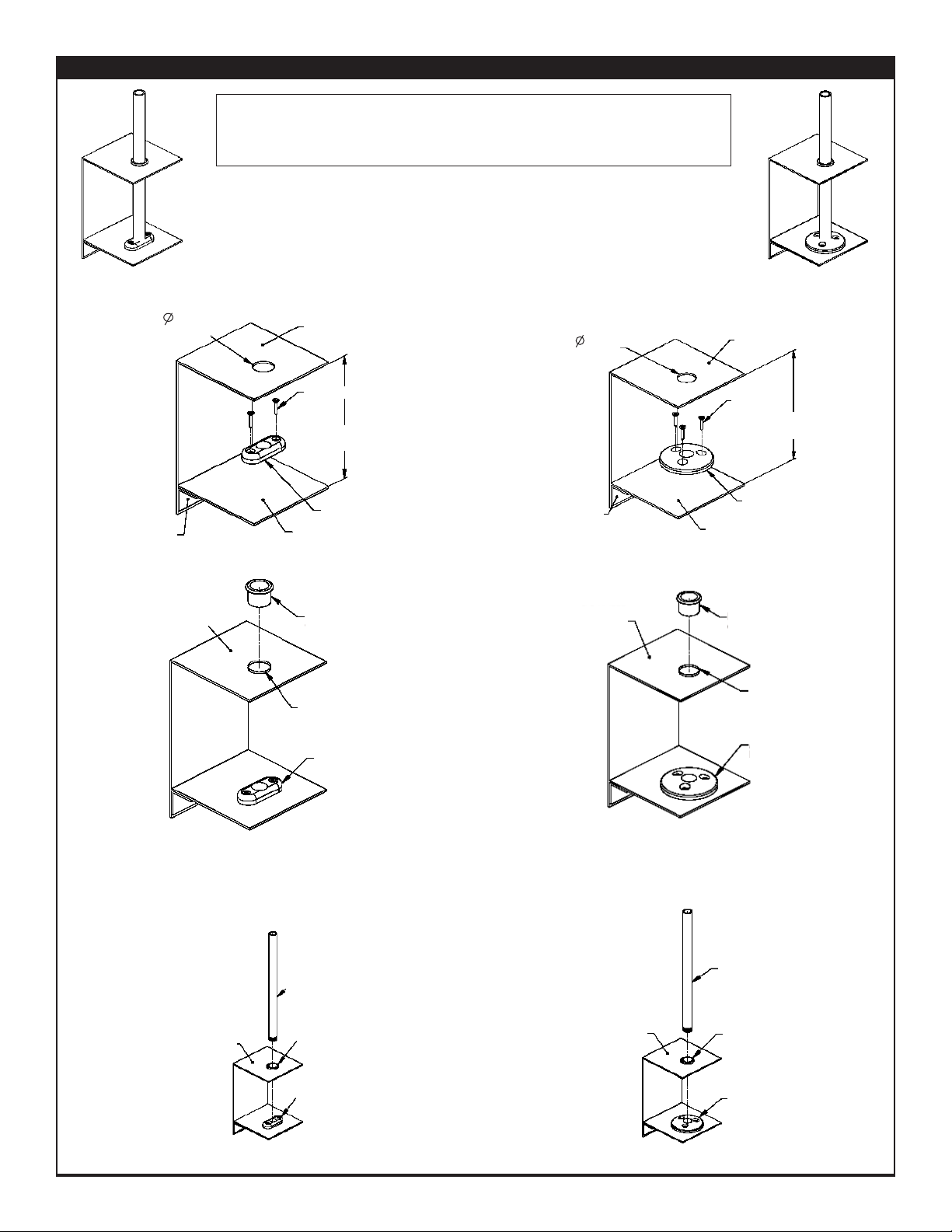
FIGURE 1
Remove mount flanges from posts. Fasten mount flange to lower plate using
screws provided. For shallow under-counter depths, a bolt and nut may be
required for ease of installation. Tighten mount screws securely.
FIGURE 2
Install grommet into post
hole in mounting surface.
Press into hole in
mounting surface until
completely seated.
FIGURE 3
Install POST from above counter surface through grommet and securely tighten into mounting flange below. It may be necessary
to access post from underside of mounting surface to align post with flange.
UNDER-COUNTER
DEPTH
SCREW
COUNTER
SURFACE
HEAVY-DUTY
FLANGE
ANGLE
(BY OTHERS)
LOWER PLATE
(BY OTHERS)
1.25”
THRU
POST
HOLE
NYLON
GROMMET
COUNTER
SURFACE
Under-Counter Heavy-Duty Flange
Mount for Stainless Steel Counters
Under-Counter Narrow Flange
Mount for Stainless Steel Counters
HEAVY-DUTY
FLANGE
Determine flange mounting locations based on centerline dimensions and, if
necessary, drill holes accordingly in counter surface. Hole diameter to be 1-1/4"
thru counter surface. Lower plate and angle to be installed below mounting
location by others.
Figure 1
COUNTER
SURFACE
SCREW
NARROW FLANGE
UNDER-COUNTER
DEPTH
LOWER PLATE
(BY OTHERS)
ANGLE
(BY OTHERS)
1.25”
THRU
Figure 2
COUNTER
SURFACE
MOUNTED
FLANGE
POST HOLE
NYLON
GROMMET
Figure 3
POST
COUNTER
SURFACE
GROMMET
HEAVY
MOUNTED
FLANGE
POST
GROMMET
NARROW
MOUNTING
FLANGE
COUNTER
SURFACE
Page 8
FOR INSTALLATION QUESTIONS PLEASE CONTACT A BRASS SMITH REPRESENTATIVE AT 1.800.662.9595
Figure 5
LOWER PLATE
THREADED END OF
POST
NARROW
FLANGE
COUNTER
SURFACE
Figure 6
SCREW
HEAVY-DUTY
FLANGE
LOWER
PLATE
1” POST
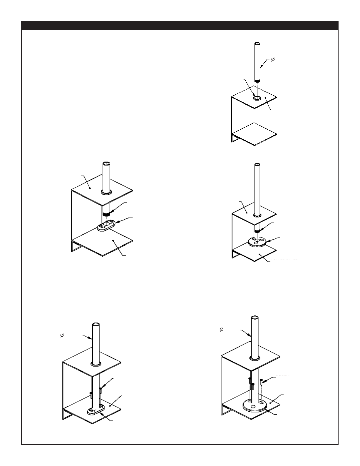
FIGURE 6
With flange secured to post, screw flange into lower plate
from underside of counter surface as shown. Securely tighten
all screws.
FIGURE 5
With post in lowered position, attach flange to threaded portion of post from
underside of counter surface. Tighten securely.
Figure 5
COUNTER
SURFACE
THREADED
END OF POST
HEAVY-DUTY
FLANGE
LOWER PLATE
Figure 4
COUNTER
SURFACE
GROMMET
1” POST
FIGURE 4
If unit has heat and/or lights, unit will arrive assembled. For pre-assembled
units or units with front and rear posts, remove mount flange from post.
Lower post through grommet and mounting surface.
Partial disassembly for food shield may be required for ease of lifting. DO
NOT REMOVE GLASS CLAMPS FROM POSTS. For units with electrical
requirements, feed wire chase through grommet and mounting surface
before lowering post into position. Avoid damaging wires.
Under-Counter Narrow - SSU3(E) & Heavy-Duty Flange Mount - SSU3(E) for Stainless Steel Counters (Cont.)
NARROW
FLANGE
LOWER
PLATE
SCREW
1” POST
Page 9
FOR INSTALLATION QUESTIONS PLEASE CONTACT A BRASS SMITH REPRESENTATIVE AT 1.800.662.9595
Under-Counter Hat Channel for Narrow (not shown) & Heavy Duty Flange Mount - SSU3(E)
Figure 1
Figure 2
Figure 3
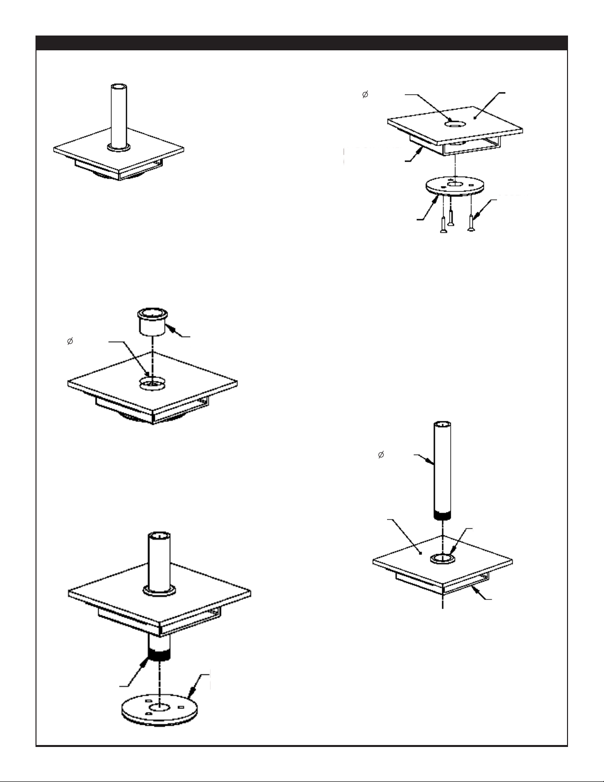
FIGURE 1
Determine flange mounting
locations based on centerline
dimensions and, if necessary,
drill holes accordingly. Hole
diameter to be 1-1/4" thru
counter surface and hat
channel. Hat channel to be
installed below mounting
location by others.
Remove mount flange and
fasten to hat channel using
screws provided. Tighten
Securely.
FIGURE 2
Install grommet into post hole in counter surface.
Press into hole until completely seated.
FIGURE 3
If unit has heat and/or lights, unit will arrive assembled.For preassembled units or units with front and rear posts, lower POST
through grommet, counter surface and hat channel. Attach flange to
post and fasten to hat channel. Partial disassembly of food shield
may be required for ease of lifting. DO NOT REMOVE GLASS
CLAMPS FROM POSTS. For units with electrical requirements, feed
wire chase through grommet, mounting surface and hat channel
before lowering post into position. Avoid damaging wires.
FIGURE 4
With post in lowered position, attach heavy-duty flange
to threaded portion of post from underside of hat
channel. Tighten securely.
Figure 4
COUNTER
SURFACE
THREADED
PORTION
OF POST
NYLON GROMMET
COUNTER
SURFACE
HAT CHANNEL
NYLON
GROMMET
HEAVY-DUTY
FLANGE
HEAVY-DUTY FLANGE IN
BELOW-COUNTER
POSITION
SCREW
HAT CHANNEL
(BY OTHERS)
1.25” THRU
1” POST
1.25 THRU
Under-Counter Hat Channel and Heavy Duty Flange
Page 10
FOR INSTALLATION QUESTIONS PLEASE CONTACT A BRASS SMITH REPRESENTATIVE AT 1.800.662.9595
Under-Counter Hat Channel & Heavy-Duty Flange Mount - SSU3(E) (Continued)
Figure 5
FIGURE 5
With heavy-duty flange secured to post, fasten flange onto hat
channel from underside of hat channel as shown. Securely
tighten all screws.
FIGURE 6
For units shipped loose, single vertical posts, cantilever, or
units without electrical requirements, lower post through
grommet, counter surface, and hat channel, and tighten into
previously installed heavy-duty flange. Tighten securely.
If unit is cantilever, apply thread glue to threads of post and
tighten as far as possible while keeping top post in desired
direction. Avoid using top post to tighten. Repeat process for all
required mounting locations.
HAT CHANNEL
HEAVY-DUTY
FLANGE
COUNTER
SURFACE
SIDE VIEW
NYLON
GROMMET
HEAVY-DUTY FLANGE
1” POST
HAT CHANNEL
SCREWS
Figure 6
Page 11
FOR INSTALLATION QUESTIONS PLEASE CONTACT A BRASS SMITH REPRESENTATIVE AT 1.800.662.9595
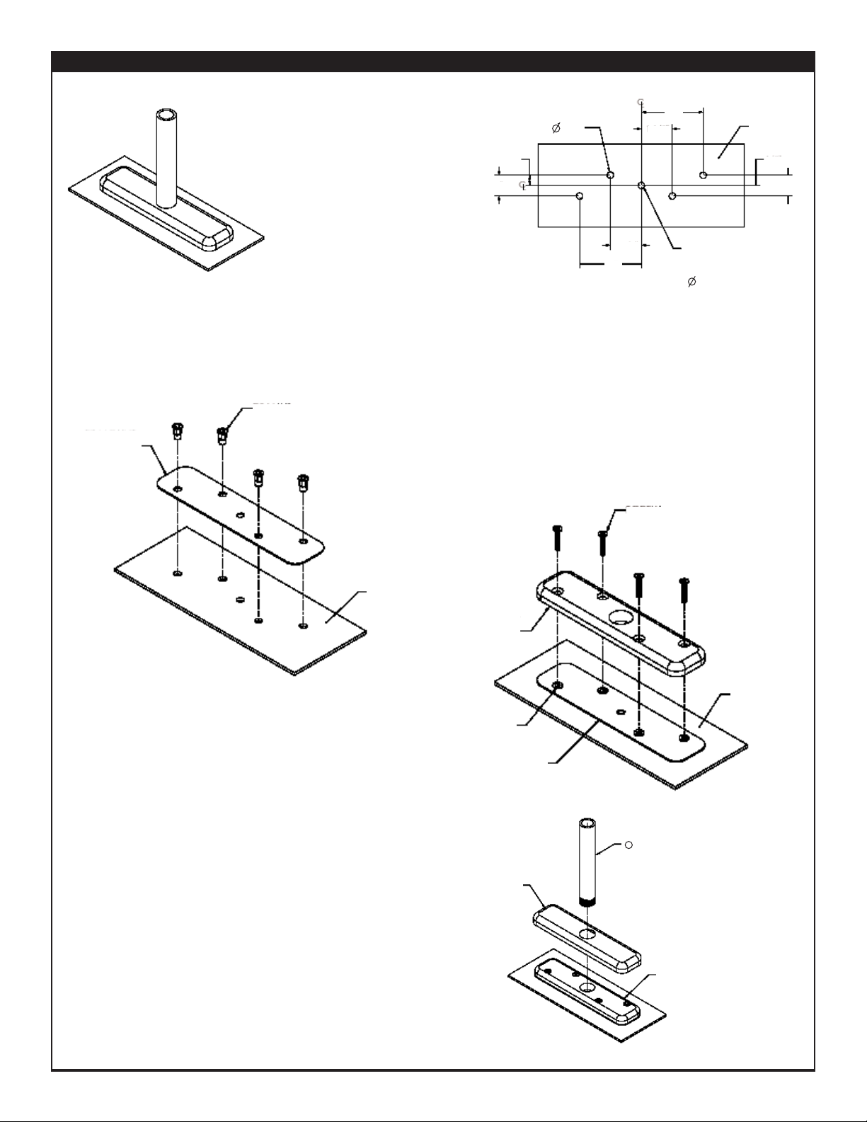
Centered EZ Mount Flange - SS1
Figure 1
Figure 2
Figure 3
Figure 4
FIGURE 4 (Flange Cover & Post Installation)
Place flange cover over EZ mount flange. Install 1" diameter
post by screwing into flange. For straight posts, tighten
securely.
For cantilever posts, add provided glue to post threads and
tighten as far as possible while keeping direction of horizontal
top post in desired direction (i.e., parallel with flange, etc).
Repeat process for all required mounts.
FIGURE 3
(Mount Flange Installation)
Align holes on EZ mount flange with holes in base plate.
Fasten flange to base plate using screws provided. Tighten
screws into RIV nuts completely.
FIGURE 2
Fasten EZ mount base plate to counter. Use four provided RIV nuts and one provided hex head screw. Completely tighten each
RIV nut using hex head screw, ensuring that RIV nuts are completely compressed beneath mounting surface. Remove hex head
screw after compressing each RIV nut.
FIGURE 1 (Base Plate Installation)
Determine flange mounting
locations based on centerline
dimensions and, if necessary, drill
holes accordingly in mounting
surface to the dimensions shown.
(Note that center mount hole is
optional and also the center of the
1" diameter post. This hole will be
punched larger for wire chase on
units with electrical requirements).
MOUNTING
SURFACE
MOUNTING
SURFACE
EZ MOUNT
FLANGE
RIV NUT
SCREW
LOCATOR HOLE CENTER WILL
ALSO BE CENTER OF
1” POST
BASE
PLATE
FLANGE
COVER
MOUNTING
FLANGE
1” POST
MOUNTING
SURFACE
RIV NUT
EZ MOUNT
BASE PLATE
1/2”
1”
3”
1 1/2”
3”
1 1/2”
1/2”
1”
5/16”
5X
Centered EZ Mount Flange
Page 12
FOR INSTALLATION QUESTIONS PLEASE CONTACT A BRASS SMITH REPRESENTATIVE AT 1.800.662.9595
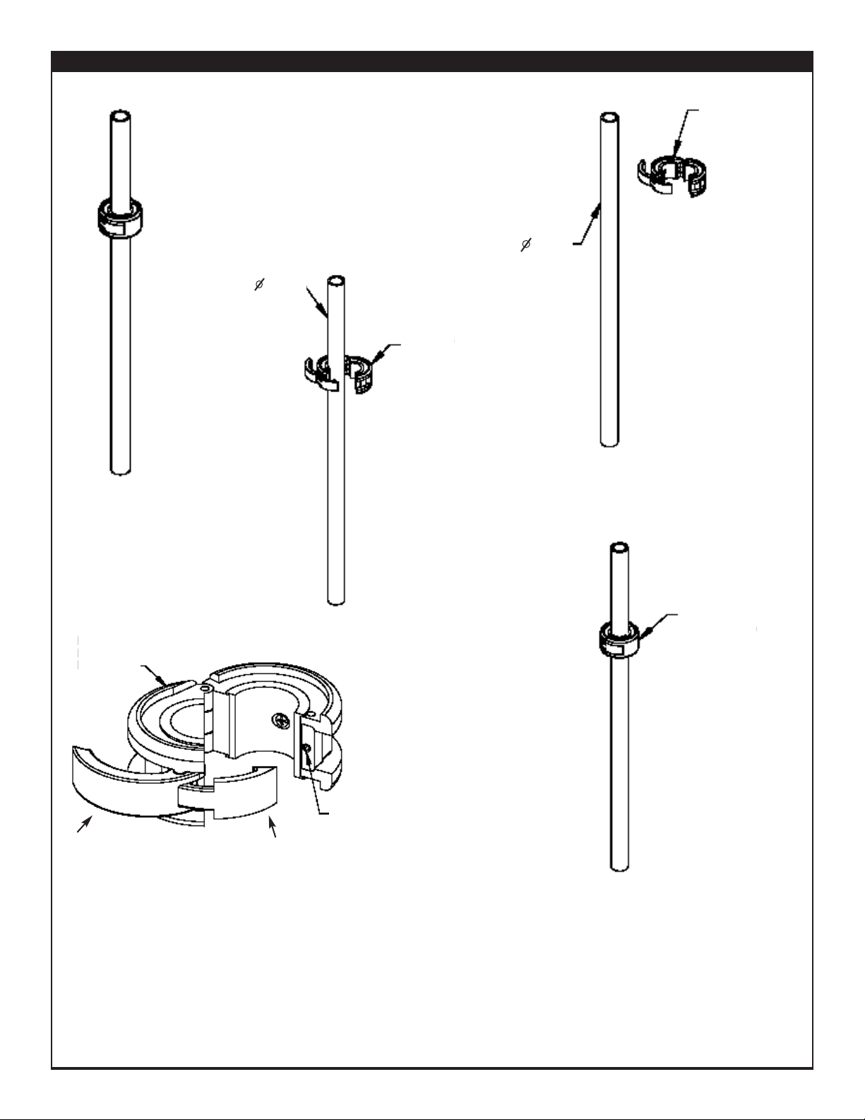
ZSpace EZ-Clamp
Figure 1
Figure 3
Figure 2
Figure 4
FIGURE 4
If clamp is too tight or too loose on post, it requires adjustment. Open clamp and locate the adjustment screw on the inside face
of the clamp (opposite bracket).
If clamp is too tight, tighten the adjusting screw using a 5/64" allen wrench in small increments. Check fit on post after each slight
adjustment until proper fit is achieved.
If clamp is too loose, loosen the adjusting screw using a 5/64" allen wrench in small increments. Check fit on post after each slight
adjustment until proper fit is achieved.
FIGURE 3
Squeeze clamp
shut and close by
hooking bracket
latch over clamp.
Press latch handle
into clamp until fully
closed. Clamp
should fit tightly
over post with no
movement.
FIGURE 2
With clamp in open position, place over 1"
diameter post at desired height. Make sure post is
centered within inner sleeve of clamp.
FIGURE 1
Open EZ CLAMP by prying open latch. Open
clamp to fullest extent.
EZ CLAMP IN
OPEN POSITION
ADJUSTMENT
SCREW
(5/64” SS CUP)
EZ CLAMP
IN OPEN
POSITION
EZ CLAMP
1” POST
EZ CLAMP IN
CLOSED
POSITION
1” POST
ZSpace EZ Clamp
BRACKET
LATCH
LATCH
HANDLE
 Loading...