

Page 1
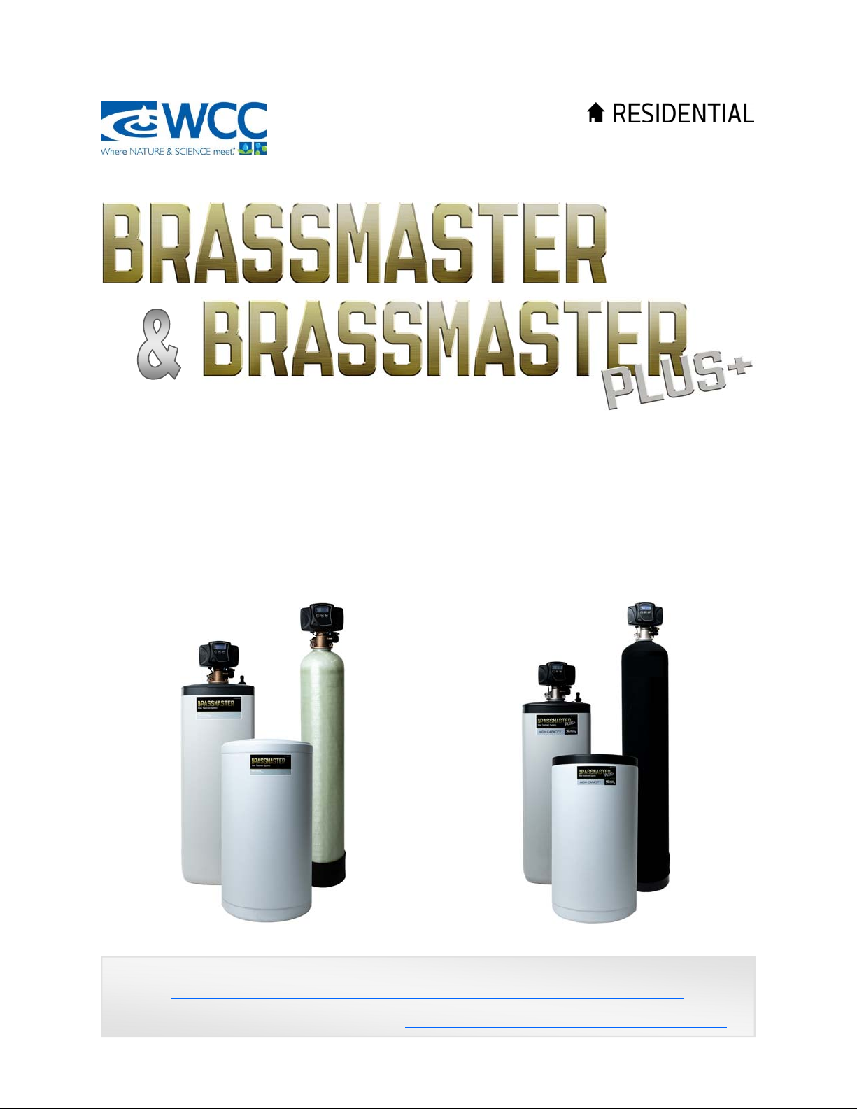
Water Softener
Installation / Operation Manual
BrassMaster and BrassMaster Plus Technical Video Library:
https://watercontrolinc.com/residential-technical-support/residential-technical-videos
BrassMaster technical videos demonstrate how to set up or remove the control module.
Replacement control modules are available at https://watercontrolinc.com/residential-technical-support/
Page 2

Specifications
Minimum inlet pressure 20 PSIG
Maximum outlet pressure 125 PSIG
Minimum water temperature 34
Maximum water temperature 110
Power
Feedwater
O
F
O
F
Voltage 120VAC
Frequency 60Hz
Power consumption 3 Watts Maximum
Installation
Location Indoors (Protect from direct sunlight)
Minimum ambient temperature 34
Maximum ambient temperature 122
Salt Capacity
O
F
O
F
Cabinet models 200 lbs
Two-Tank models 300 lbs
Maximum Flow To Drain
B24 (0.66 ft
B32 (0.80 ft
BT24 (0.60 ft
BT32 (0.80 ft
BT48 (1.30 ft
BT60 (2.00 ft
3
resin) – 2.0 GPM* BP27 (0.85 ft3 resin) – 2.0 GPM*
3
resin) – 1.7 GPM* BP35 (0.92 ft3 resin) – 3.5 GPM*
3
resin) – 1.7 GPM* BPT27 (0.82 ft3 resin) – 2.0 GPM*
3
resin) – 1.7 GPM* BPT35 (1.10 ft3 resin) – 3.5 GPM*
3
resin) – 2.4 GPM* BPT48 (1.30 ft3 resin) – 3.5 GPM*
3
resin) – 4.0 GPM* BPT60 (2.00 ft3 resin) – 5.0 GPM*
WB24 (0.75 ft
WB32 (1.0 ft
WBT24 (0.75 ft
WBT32 (1.0 ft
WBT48 (1.5 ft
WBT60 (2.0 ft
3
resin) – 1.7 GPM* WBP27 (0.90 ft3 resin) – 2.0 GPM*
3
resin) – 2.0 GPM* WBP35 (1.15 ft3 resin) – 2.0 GPM*
3
resin) – 1.7 GPM* WBPT27 (0.90 ft3 resin) – 2.0 GPM*
3
resin) – 2.0 GPM* WBPT35 (1.15 ft3 resin) – 2.0 GPM*
3
resin) – 2.4 GPM* WBPT48 (1.5 ft3 resin) – 2.4 GPM*
3
resin) – 4.0 GPM* WBPT60 (2.0 ft3 resin) – 4.0 GPM*
* rated drain flow during regeneration
Note: This system is not intended to be used for treating water that is microbiologically
unsafe or of unknown quality without disinfection before or after the system.
Wisconsin units conform to ANSI/NSF-44 for specific performance claims as verified and substantiated by test data.
2
Page 3

Installation Procedure
1. Identify installation location for water softener. Piping should be such that all household
water, with the exception of outside hydrants, flows through softener. A hard water line
may be run to a kitchen tap if so desired. This system and installation must comply with
state and local laws and regulations.
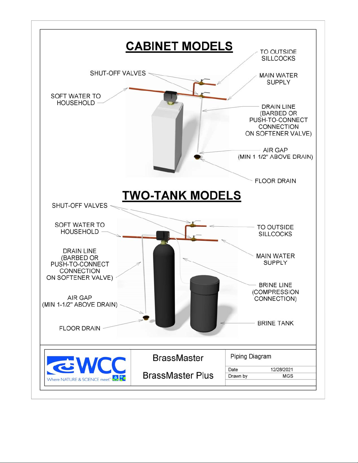
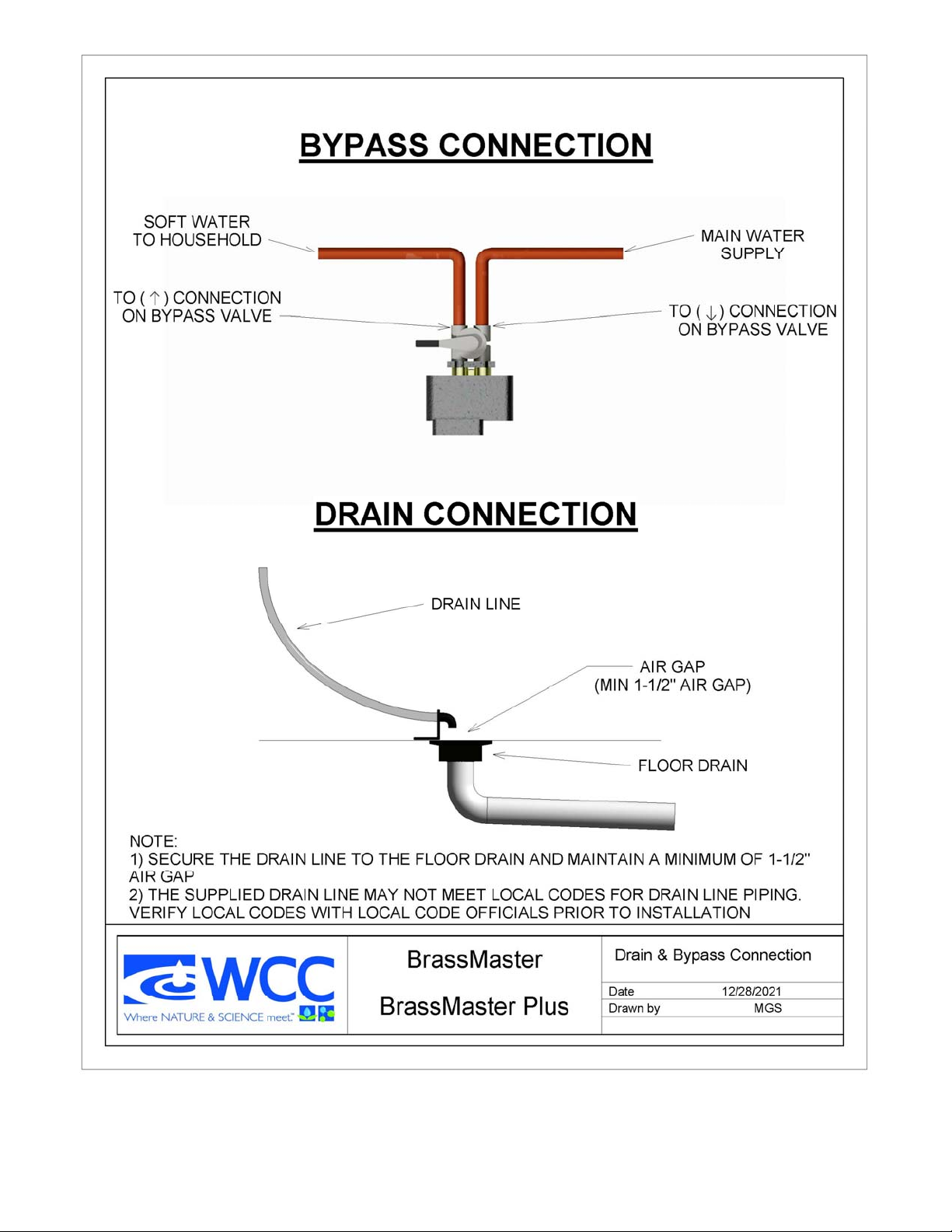
2. Connect water piping. This unit has been supplied with a manually operated bypass device
which enables the softener to be isolated from the water service lines for maintenance and
service, and also maintain the continuity of the water supply when the softener is discon-
nected. Important: Make all sweat-solder connections within 6 inches of softener before
applying threaded fittings to supplied bypass valve. Overheating may cause damage to
valve. Turn supplied bypass valve to “Bypass” position and make connections to household
water lines. Leave unit in “Bypass” position until startup procedure.
3. Connect drain line. Remove barbed or push-to-connect drain line fitting from parts bag.
Apply thread seal tape to threads, and turn into the female threaded opening on the back
side of the control valve. Connect 5/8” drain line (supplied in parts bag) to barbed or pushto-connect end of drain line fitting, and run to a nearby drain.
IMPORTANT: It is highly recommended that a hose clamp be used to secure tubing to
drain fitting to ensure tubing from being removed during elevated pressure situations.
Be sure not to submerse drain line end into drain, as a 1 1/2” minimum air gap must be
maintained to prevent potential backflow hazard. Firmly secure at drain, while maintaining
a minimum 1 1/2” air gap (See detailed drawing on back side of piping diagram).
4. Connect brine line (two-tank models only). Connect 3/8” brine line (supplied in parts
bag) to fitting on brine tank, and on the control valve. Tighten both fittings with an adjustable wrench.
5. Install brine tank overflow line. Install overflow fitting (supplied in parts bag) into hole in
side of brine tank. An owner-supplied overflow line should then be attached and run to a
nearby drain. Failure to run overflow line could cause flooding and water damage should
the brine tank overflow.
6. Connect to electrical power source. Connect power cord to a separate 120v, 15 amp,
ground fault interrupt (GFI) outlet.
Proceed to start-up procedure.
Note: This system is not intended to be used for treating water that is microbiologically
unsafe or of unknown quality without disinfection before or after the system.
3
Page 4
4
Page 5
5
Page 6
Start-Up Procedure
Placing unit into service
Normal
Operation
Mode Icon
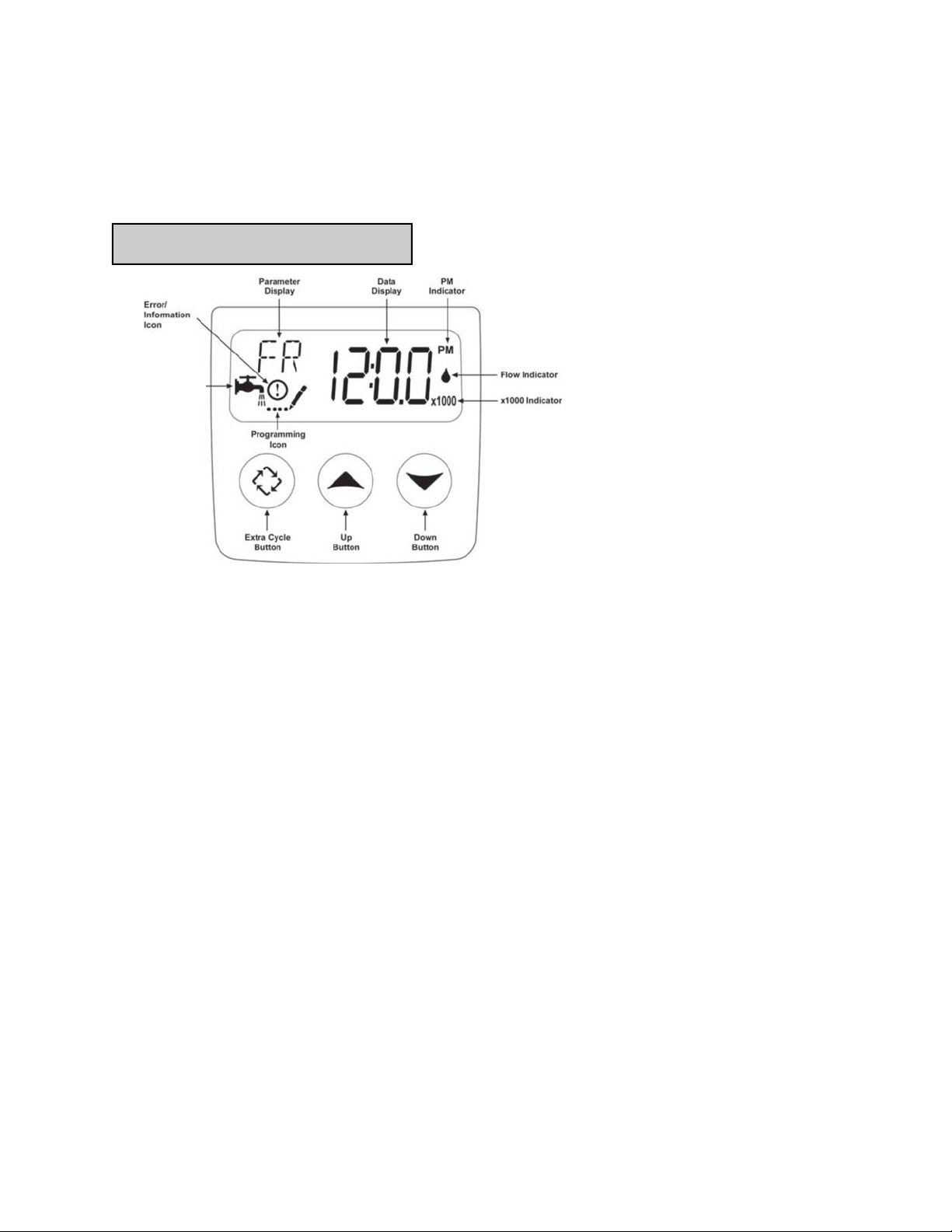
While in service, the Data Display alternates between time of day,
volume remaining or days to regeneration.
The Flow Indicator flashes when outlet flow is detected.
The Faucet Icon flashes if a regeneration cycle has been queued.
1. Fill the mineral tank with water
Keep softener in BYPASS
Press and hold the extra cycle button for 5 seconds, display will indicate BW, Backwash
cycle.
Push extra cycle button once and let go, display will indicate BD, Brine Draw cycle.
Push extra cycle button again and let go, display will indicate RR, Rapid Rinse cycle.
Slowly open bypass valve and allow water to flow for 2-4 minutes. This will allow the
media in the tank to become saturated.
Open bypass valve to the service position.
Push extra cycle button once and let go, display will indicate BF, Brine Fill cycle.
Allow timer to fill the brine tank for the entire time on the display. The unit will advance
to the service position when completed.
Push extra cycle button for 5 seconds, this will start a manual regeneration from start-to-
finish. This will take approximately two hours.
Start-up procedure is now complete.
The unit is now pressurized with water and ready for service.
Proceed to setting current time of day.
6
Page 7
Start-Up Procedure (continued)
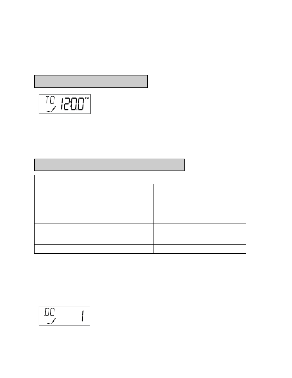
Setting current time of day
Setting Current Time / Day
1. Press either the Up or Down buttons to adjust current time of day by one digit. Push and
hold either up or down set button to adjust current time of day display by several digits.
User programming
User Programming Mode Options
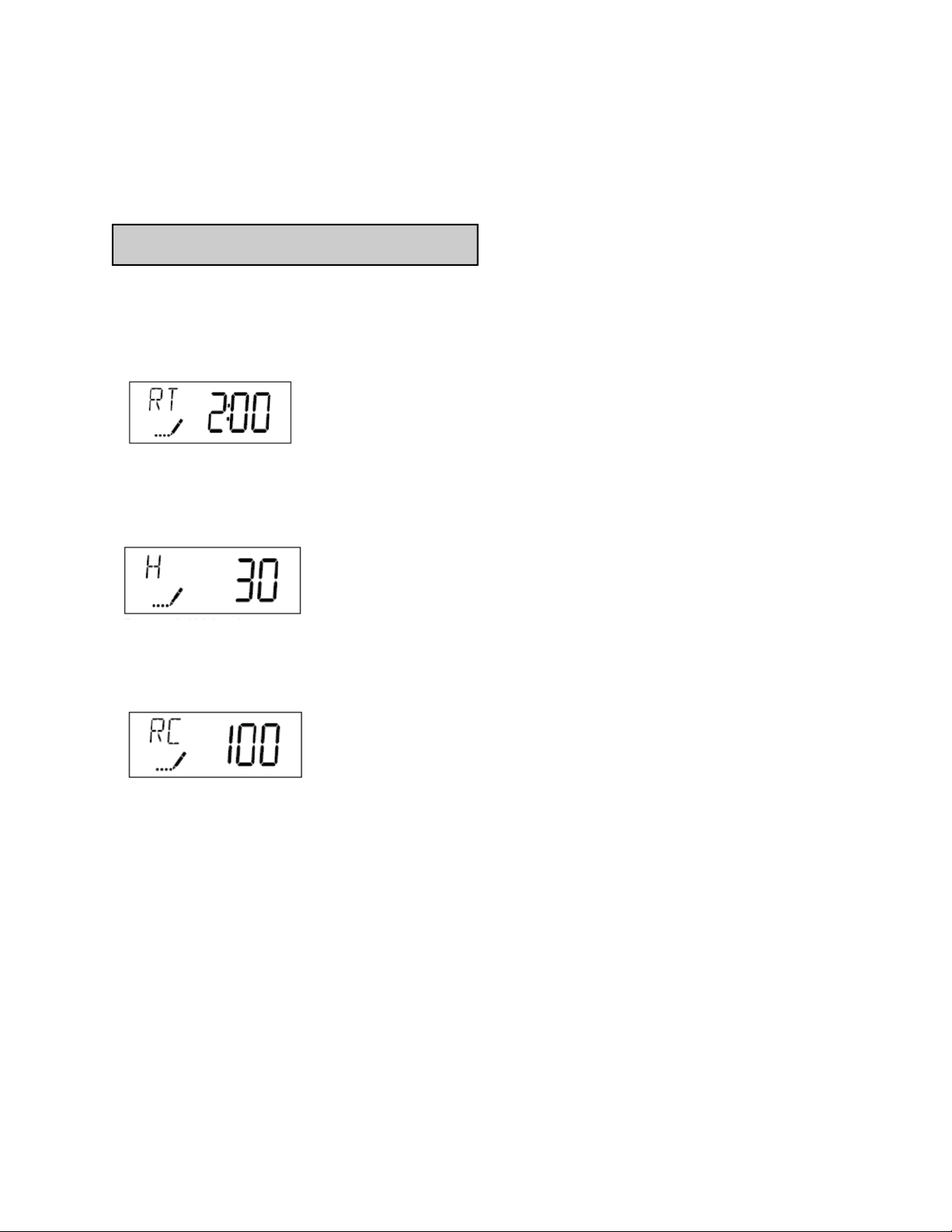
Abbreviation Parameter Description
DO Day Override The timer’s day override setting
RT Regeneration Time The time of day that the system will
regenerate (meter delayed, timeclock,
and day-of-week systems)
H Feed Water Hardness The hardness of the inlet water—
used to calculate system capacity for
metered systems
RC Reserve Capacity The fixed reserve capacity
User Programming Mode Steps (Refer to chart above for user mode indications)
1. Press the Up and Down buttons for five seconds while valve is in service. Display will enter
programming mode. (Note: Timer will discard any changes and exit programming mode if
any button is not pressed for sixty seconds.
7
Page 8
Start-Up Procedure (continued)
User programming (cont’d)
2. Set Day Override: This setting specifies the maximum number of days between regenera-
tion cycles. System will regenerate regardless of usage if the days since last regeneration
cycle equals the day override setting. This ensures regular regeneration periods. In areas of
heavy iron water conditions, this setting should not exceed 5 days.
3. Adjust Regeneration Time: Press the Extra Cycle button to advance to next option. This
setting determines the time of day that the unit will enter the regeneration cycle. The most
common / default setting is 2:00 AM.
4. Set Water Hardness: Press the Extra Cycle button to advance to next option. Set the hard-
ness of the incoming water. For each PPM of iron, add 4 GPG to this setting. This will determine the amount of water usage allowed between regeneration cycles.
5. Set Fixed Reserve Capacity : Press the Extra Cycle button to advance to next option. Set
the Fixed reserve capacity for the household. This is the amount of water needed in reserve to
reach the delayed regeneration time. Standard setting is 50 gallons for each person in the
household.
Control programming is now complete. Press the extra cycle button, and the control will
exit from the programming mode and resume normal operation.
Sanitization of Unit
After complete installation of unit, dilute 1/2 cup of unscented laundry bleach in 3 gallons of
water, and add to brine tank. Initiate a manual regeneration by depressing the extra cycle button. Allow the unit to complete its cycle and advance to the “Service” position. The unit is now
sanitized and ready for operation.
8
Page 9

Softener Operation
As water enters the softener, it passes over a resin bed in a special tank. The resin consists of
tiny beads of a plastic called styrene. These beads attract and hold sodium ions and exchange
the sodium for hardness ions when encountered. Over time, the resin becomes saturated with
hardness ions and no longer removes hardness materials. The softener goes into a
"regeneration" to flush hardness materials to the drain and refresh the resin with sodium. Regeneration is typically programmed to take place in the middle of the night when little or no water is in use.
Regeneration consists of four cycles:
1. Backwash Position
Backwash is a rapid upward flow of water that loosens the resin bed and flushes iron particles,
dirt and sediments filtered in the bed out to the drain.
2. Brine Draw / Slow Rinse Position
Brine Draw is the process in which brine is drawn out of the brine cabinet and passed through
the resin in a downward direction. This rinses the resin and large amounts of sodium ions replace the hardness ions accumulated during service.
Slow Rinse. After brine is completely removed from the brine cabinet into the resin tank the
brine valve closes. Water replaces any remaining brine from the resin, flushing hardness ions
removed from the resin to drain.
3. Fast Rinse Position
Fast Rinse is a fast flow of water down through the resin tank that follows a Backwash. This
flushes all remaining brine from the tank and packs the resin bed for softening efficiency.
4. Brine Fill
Brine is water saturated with large amounts of a salt (sodium chloride). During Brine Fill, water flows into the salt storage area after each regeneration and dissolves salt. During the regeneration process, hardness ions on the resin beads are replaced or exchanged for sodium ions
from the brine solution.
5. Service
When the softener is in Service it is flowing water through the system and removing hardness
minerals from your water.
9
Page 10

Service
Checking for a Salt Bridge
A hard crust or "Salt Bridge" can form in the lower half of the salt storage tank. This can be deceiving because the tank will appear to have plenty of salt, but underneath, salt has hardened
and when the system regenerates, water cannot quite reach this level to be made into brine
(water and salt).
Breaking a Salt Bridge
Take a wooden broom handle and carefully push it down into the salt, working it up and down.
If the tool strikes a hard object (be sure it's not the bottom or sides of the tank), it's probably a
salt bridge. Carefully break the bridge with the broom handle. Do not pound on the walls of the
tank.
NOTE: Salt bridges are typically caused by high humidity or using the wrong kind of salt. In
humid areas it is best to fill with less salt, more often. Use only nugget, pellet or coarse solar
salt with a purity of 99.5% or higher. DO NOT use rock, block, granulated, and ice creammaking salts, or salt with iron-removing additives.
Cleaning the Brine Injector Assembly
It is recommended to clean the injector and injector screen annually to ensure proper system operation.
From time-to-time, a softener’s brine water injection assembly can become plugged with dirt
and debris. This results in poor softener regeneration, which (in-turn) can lead to poor softening
performance. Plugging of a brine injector can also cause brine tanks to fill up with water, and
eventually overflow.
Cleaning and unplugging a dirty brine injector is an easy process. For a detailed instructional
video, please visit: https://watercontrolinc.com/residential-technical-videos/
10
Page 11
Troubleshooting
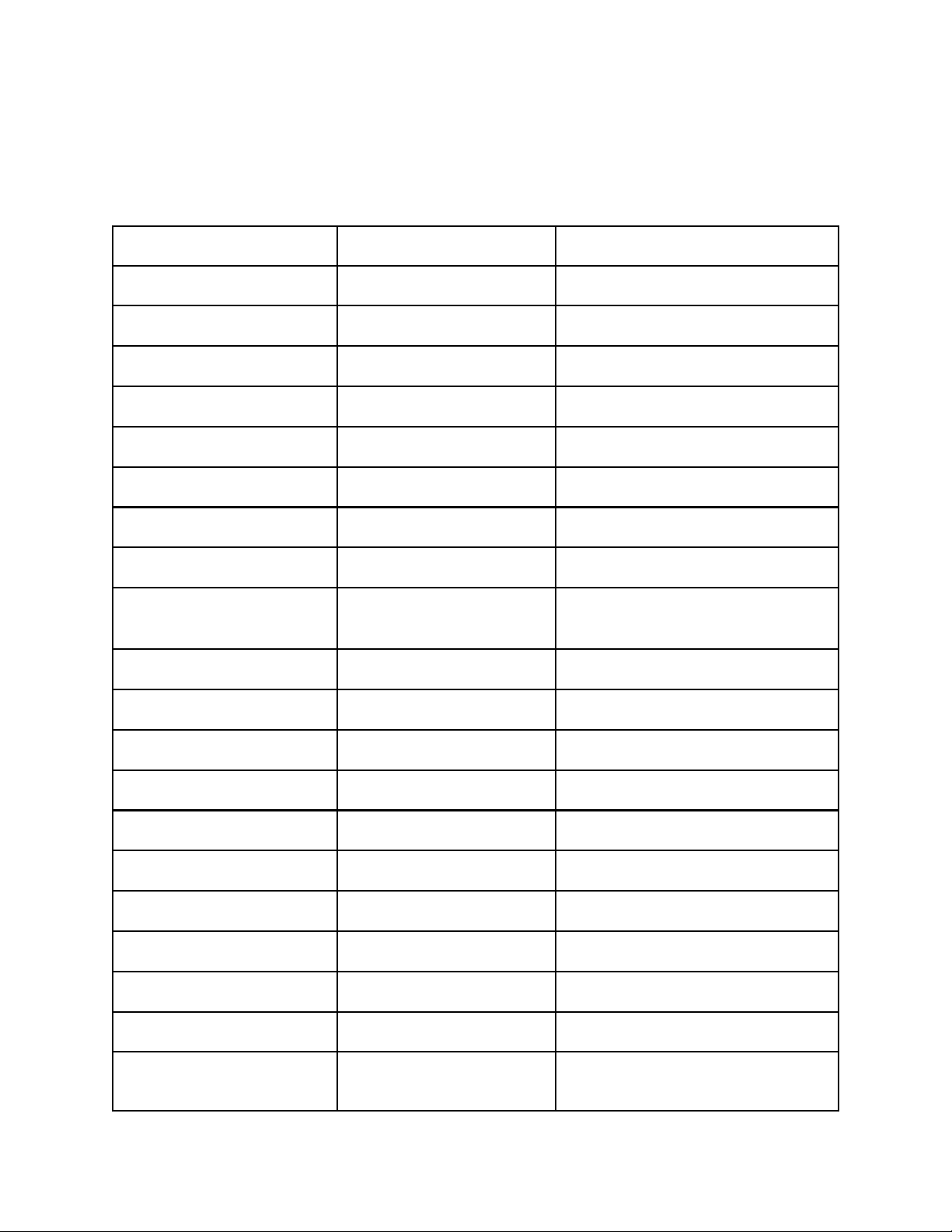
1. Softener Fails To Regenerate.
2. Softener Delivers Hard
Water.
A. Electrical service to unit has
been interrupted.
B. Timer programming bad
(improper programming).
A. By-pass valve is open. A. Close by-pass valve.
B. No salt in brine tank. B. Add salt to brine tank and maintain salt
C. Injectors or screen plugged. C. Clean or replace injectors and screen.
D. Insufficient water flowing into
brine tank.
E. Hot water tank hardness. E. Repeated flushings of the hot water tank
F. Flow meter jammed. F. Check flow indicator light for flow. Re-
G. Flow meter cable disconnected
or not plugged into meter.
H. Improper programming. H. Reprogram the control to the proper re-
I. Plugged brine line or air check. I. Remove and clean any sediment from
J. Salt bridge has formed. J. Refer to Breaking a Salt Bridge section in
K. No water in brine tank. K. Ensure safety float is not stuck.
A. Assure permanent electrical service
(check fuse, plug, pull chain or switch).
B. Check programming and reset as needed.
level above water level.
D. Check brine tank fill time and clean
brine line flow if plugged.
is required.
move obstruction from flow meter.
G. Check meter cable connection to timer
and meter.
generation type, inlet water hardness,
capacity or flow meter size.
brine tank and brine valve assembly.
manual.
3. Unit Uses Too Much Salt.
4. Loss of Water Pressure.
L. Unit is plumbed backwards. L. Check that the unit is plumbed correctly.
M. Water hardness has increased
or is set incorrectly.
N. Water pressure is too low. N. Line pressure must be at least 20 PSI.
A. Improper salt setting. A. Check salt usage and salt setting.
B. Excessive water in brine tank. B. See problem No. 7.
C. Improper programming. C. Check programming and reset as needed.
A. Iron buildup in line to water
conditioner.
B. Iron buildup in water condi-
tioner.
11
M. Retest hardness and change settings.
A. Clean line to water conditioner.
B. Clean control and add resin cleaner to
resin bed. Increase frequency of regeneration.
Page 12

Troubleshooting (continued)
5. Loss of Resin Through Drain
Line.
6. Iron in Conditioned Water.
7. Excessive Water in Brine
Tank.
8. Salt Water in Service Line.
A. Air in water system. A. Assure that well system has proper air
eliminator control and check for dry well
condition.
B. Drain line flow control is too
large.
A. Fouled resin bed. A. Check backwash, brine draw and brine
B. Iron content exceeds recom-
mended parameters.
A. Plugged drain line flow con-
trol.
B. Brine valve failure. B. Clean brine valve.
C. Improper programming. C. Check programming and reset as needed.
A. Plugged injector system. A. Clean injector and replace screen.
B. Improper programming. B. Check programming and reset as needed.
C. Foreign material in brine C. Clean or replace brine valve.
D. Foreign material in brine line D. Clean brine line flow control.
E. Low water pressure. E. Raise water pressure.
B. Ensure drain line flow control is sized
correctly.
tank fill. Increase frequency of regeneration. Increase backwash time.
B. Add iron removal filter or system.
A. Clean flow control.
9. Softener Fails to Draw Brine.
10. Drain Flows Continuously.
12. Loss of capacity.
A. Drain line flow control is
plugged.
B. Injector is plugged. B. Clean or replace injectors.
C. Improper programming. C. Check programming and reset as needed.
D. Line pressure is too low. D. Increase line pressure (line pressure must
A. Foreign material in control. A. Remove piston assembly and inspect
A. Increased raw water hardness A. Reset unit to the new capacity.
B. Brine concentration and/or
quantity.
C. Resin fouling. Future fouling. C. Call Water Control Corp, find out how to
D. Poor distribution, channeling
(uneven bed surface).
12
A. Clean drain line flow control.
be at least 20 PSI at all times.)
bore, remove foreign material & check
control in various ports.
B. Keep brine tank full of salt at all times.
Clean it yearly. Salt may be bridged. If
using a salt grid plate ensure refill water
is over it.
confirm it, clean the resin and prevent.
D. Call Water Control Corp. Check distrib-
utors and backwash flow.
Page 13
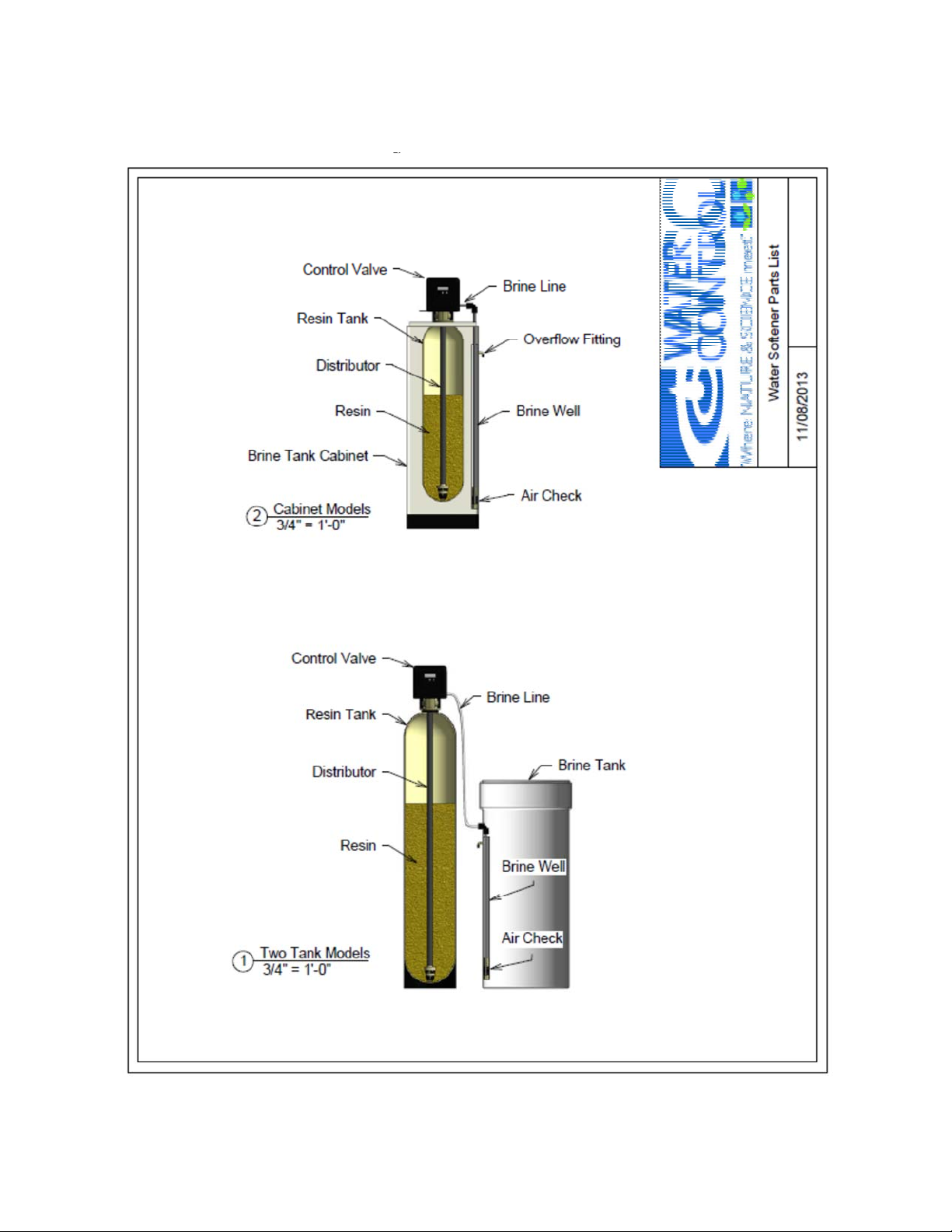
Water Softener System Parts List
Please contact Water Control Corporation or your dealer for parts availability.
13
Page 14
Maintenance / Warranty Information
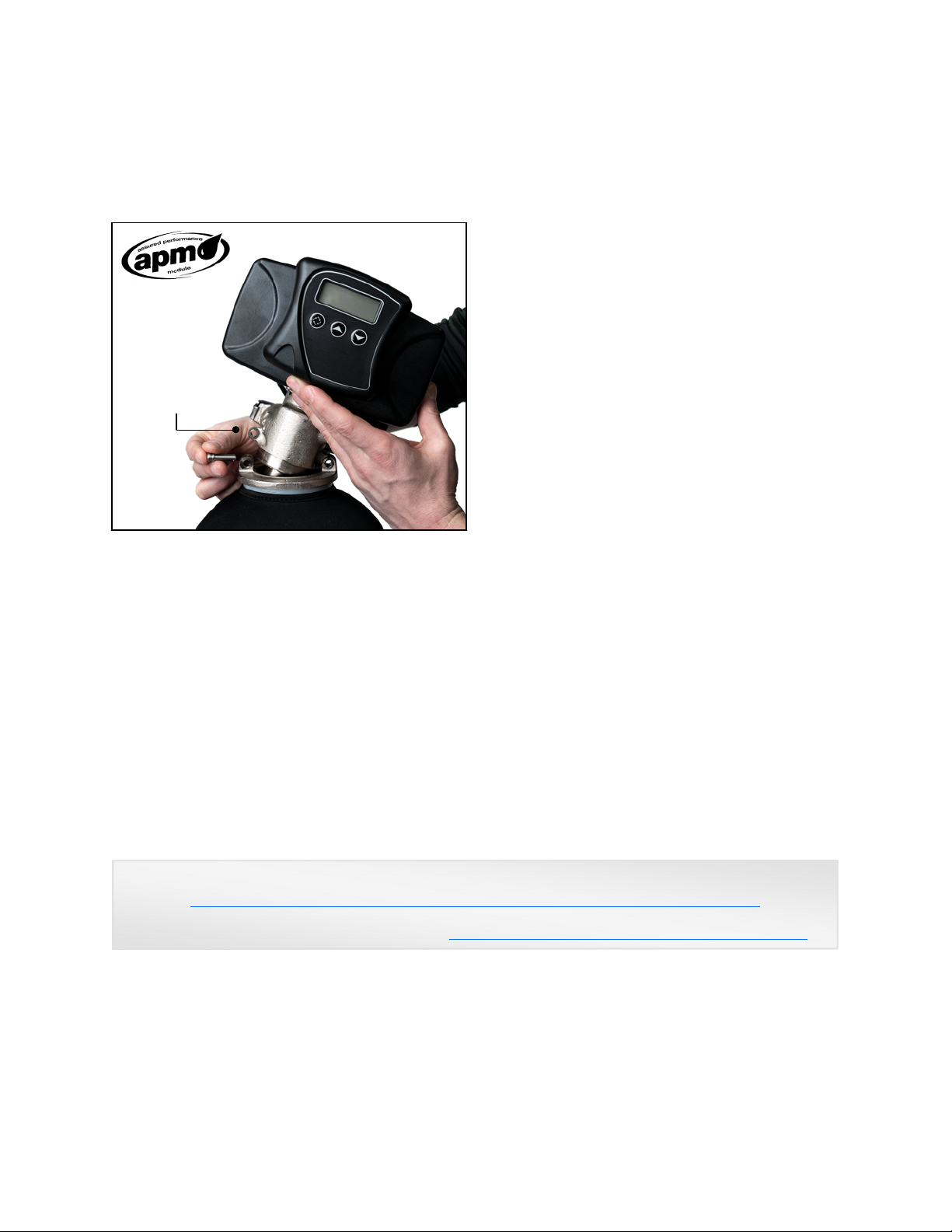
All BrassMaster and BrassMaster Plus water
softeners feature the Assured Performance
Modular (APM) design. If you experience a
failure of any valve component, the brass
module can be easily removed and replaced.
Nearly all serviceable
parts lie within the
removable / replaceable
APM module.
This eliminates costly and
time consuming field repairs.
Reference the BrassMaster and BrassMaster
Plus Technical Video Library on our website
(link is provided below) for detailed steps on
how to remove the module. The required
(downloadable) form to have your module
replaced is also located at this site.
Please contact your dealer or Water Control
Corporation for module support.
Salt Maintenance
You must keep salt in the tank. The salt tank operates best when the salt level is below half full.
If the tank is filled more than that the salt pellets may "bridge". The salt pellets wedge against
each other and do not fall into the water at the bottom. Bridging will eventually provide no salt
to make brine. The softener will recharge but not recondition the media. A salt bridge can be
broken up using a broom handle or similar rod. Carefully pound it into the salt and the pellets
will collapse. After loosening the salt pellets wait 2 hours and start a regeneration. A second
recharge may be needed to fully recondition the media. You should only use sodium chloride
pellet salt for water softeners. Other types of salt (rock or snow melting) will contain dirt and
chemicals that will affect your water softener.
BrassMaster and BrassMaster Plus Technical Video Library:
https://watercontrolinc.com/residential-technical-support/residential-technical-videos
BrassMaster technical videos demonstrate how to set up or remove the control module.
Replacement control modules are available at https://watercontrolinc.com/residential-technical-support/
For factory module support contact:
Water Control Corporation
7150 143rd Ave NW ● Ramsey, MN 55303
Phone: 1-866-405-1268 ● Fax: 763-427-5665
www.watercontrolinc.com
14
Page 15
Official Warranty
Water Control Corporation
BrassMaster Series Water Softeners
Limited Warranty
Water Control Corporation warrants the control valve to be free of manufacturers defects for a period of 3 (three) years
from the date of installation, and the fiberglass reinforced mineral tank, and plastic brine tank, to be free from leaking due
to manufacturer’s defects for a period of 5 (five) years. We will, at our discretion, repair or replace defective products.
This warranty does not include any costs associated with removal of defective products, or installation of replacement
products. All replacement parts will be provided FOB Ramsey, MN. This warranty is transferable.
DISCLAIMER OF IMPLIED WARRANTIES
Water Control Corporation makes no warranties except those expressly stated in this document. To the extent permitted by
the laws of the applicable state, ALL WARRANTIES CONTAINED IN THIS DOCUMENT ARE EXPRESSLY IN
LIEU OF, AND WATER CONTROL CORPORATION EXPRESSLY DISCLAIMS, ANY AND ALL OTHER
WARRANTIES, EXPRESS OR IMPLIED, INCLUDING THE WARRANTIES OF MERCHANTABILITY AND
FITNESS FOR A PARTICULAR PURPOSE.
WHAT IS NOT COVERED BY THESE WARRANTIES
1. Conditions and damages resulting from any of the following:
- Wear caused by unfavorable water conditions
- Improper installation, delivery, or maintenance
- Any repair, modification, alteration, or adjustment not
authorized by the manufacturer or an authorized servicer
- Misuse, abuse, accidents, or unreasonable use
- Improper setting of any control
- Incorrect electric current, voltage, or supply
2. Warranties are void if the original serial numbers have been removed, altered, or cannot be readily determined.
3. The cost of service or service call to:
- Correct installation errors
- Instruct the user on proper use of the product
- Transport the product to the servicer
4. Any costs associated with removal of defective products, or installation of replacement products.
5. Consequential, special, or incidental damages sustained by any person as a result of the breach of these
warranties. Some states do not allow the exclusion or limitation of consequential or incidental damages, so the
above exclusion may not apply to you.
15
Page 16
Official Warranty
Water Control Corporation
BrassMaster Plus Series Water Softeners
Limited Warranty
Water Control Corporation warrants the control valve to be free of manufacturers defects for a period of 5 (five) years
from the date of installation, and the fiberglass reinforced mineral tank, and plastic brine tank, to be free from leaking due
to manufacturers defects for a period of 5 (five) years. We will, at our discretion, repair or replace defective products. This
warranty does not include any costs associated with removal of defective products, or installation of replacement products.
All replacement parts will be provided FOB Ramsey, MN. This warranty is transferable.
DISCLAIMER OF IMPLIED WARRANTIES
Water Control Corporation makes no warranties except those expressly stated in this document. To the extent permitted by
the laws of the applicable state, ALL WARRANTIES CONTAINED IN THIS DOCUMENT ARE EXPRESSLY IN
LIEU OF, AND WATER CONTROL CORPORATION EXPRESSLY DISCLAIMS, ANY AND ALL OTHER
WARRANTIES, EXPRESS OR IMPLIED, INCLUDING THE WARRANTIES OF MERCHANTABILITY AND
FITNESS FOR A PARTICULAR PURPOSE.
WHAT IS NOT COVERED BY THESE WARRANTIES
1. Conditions and damages resulting from any of the following:
- Wear caused by unfavorable water conditions
- Improper installation, delivery, or maintenance
- Any repair, modification, alteration, or adjustment not
authorized by the manufacturer or an authorized servicer
- Misuse, abuse, accidents, or unreasonable use
- Improper setting of any control
- Incorrect electric current, voltage, or supply
2. Warranties are void if the original serial numbers have been removed, altered, or cannot be readily determined.
3. The cost of service or service call to:
- Correct installation errors
- Instruct the user on proper use of the product
- Transport the product to the servicer
4. Any costs associated with removal of defective products, or installation of replacement products.
5. Consequential, special, or incidental damages sustained by any person as a result of the breach of these
warranties. Some states do not allow the exclusion or limitation of consequential or incidental damages, so the
above exclusion may not apply to you.
16
Water Control Corporation
7150 143
rd
Ave NW ● Ramsey, MN 55303
Phone: 1-866-405-1268 ● Fax: 763-427-5665
www.watercontrolinc.com 1221
 Loading...