

Page 1
Installation, Operating
And
Maintenance Instructions
Nitrogen Dioxide
Gas Transmitter
BGS-ND-TRNS
1.0 Installation Procedures
1.1 MOUNTING:
The Nitrogen Dioxide Transmitter must be mounted indoors and kept dry at all times. This transmitter
should be mounted in a well-populated area, and placed so the display can be easily seen. The unit
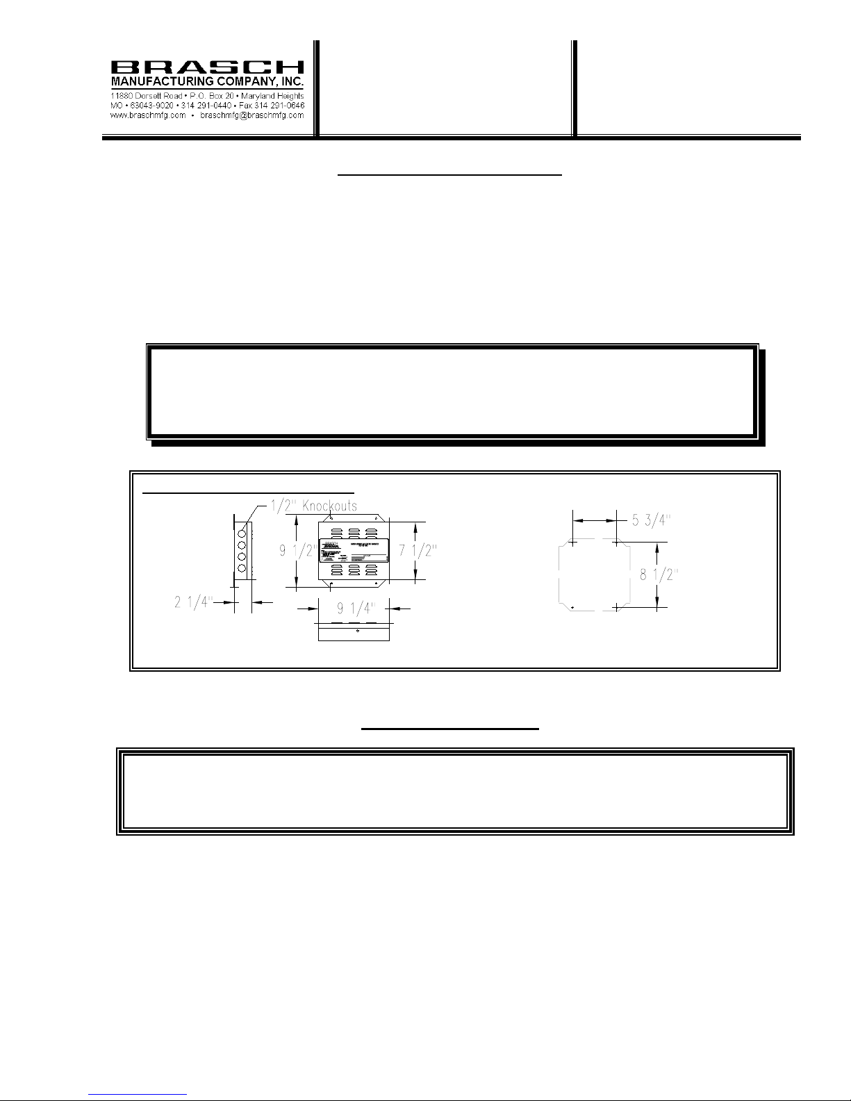
should be mounted at breathing height that is generally between 5 to 7 feet above the floor. Figure #1
shows the mounting hole locations. Mount the transmitter to a rigid surface using #10 hardware.
CAUTION:
Leave a minimum of 2” clearance to other surfaces, and under no circumstances
should the ventilation louvers in the cover be blocked. Be sure that metal shavings
and other contaminants are removed from inside the transmitter.
Figure #1 Mounting Hole Locations
1.2 WIRING:
1.21 Input Power Wiring
Use only qualified personnel for the installation of this transmitter. All wiring should be
done in accordance with l ocal codes and the latest edi tion of the National Electrical Code
(ANSI/NFPA 70).
This transmitter requires an input voltage of 24 VAC, 50/60 Hz at a load rating of 28 VA. If a grounded
24 VAC supply voltage is supplied, then the hot line should be wired to terminal T1 and the grounded
line should be wired to T2. Brasch Manufacturing Co., Inc. can provide a step-down transformer for
changing 208-240 VAC or 120 VAC at 50/60 Hz to 24 VAC at 50/60 Hz. See the 6.0 Accessories
Section (Page 4) for the transformer part numbers. The supply circuit must include a disconnect device
or switch located close to the transmitter and marked as the disconnect device for the transmitter. This
will assure continued operation without interruption from remote failures. To provide noise suppression
the input power must be wired, as shown in Figure #2 (Page 2), with the ground connected. Use copper
conductors only, rated for a minimum of 250 volts, 14 AWG.
1
BULLETIN I-680
3-2-99
Page 2
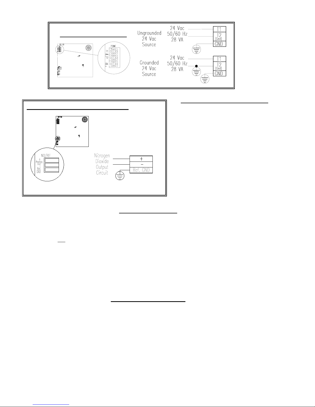
Figure #2 Input Power Wiring
Figure #3 Proportional Output Wiring
1.22 Proportional Output Wiring
See the 4.0 Specification Section (Page 3)
for minimum/maximum loads for the
proportional outputs. The wiring of the
proportional output signals is done by
lifting the white lever, inserting the signal
wire and pressing the white lever flat. Use
copper conductors only, rated for a
minimum of 250 volts, with a minimum
wire size of 26 AWG (22 AWG
maximum). Figure #3, Proportional
Output Wiring shows the wiring to a
remote Brasch Gas Detector Control
Panel, DDCS or BMS.
2.0 Unit Operation
When power is applied to the Nitrogen Dioxide Gas Transmitter the internal green power LED will
illuminate. This LED will stay ON as long as power is supplied to the transmitter. If the power ON
LED should go out, see the 5.0 Troubleshooting Section (Page 4) for help.
This Nitrogen Dioxide Gas Transmitter has one mode of operation, Normal. Upon the application of
power the unit will enter the Normal mode.
In the Normal mode the transmitter monitors the concentration of nitrogen dioxide (NO2) and generates
the proportional output signal.
3.0 Operational Settings
3.1 PROPORTIONAL OUTPUT OPTIONS
The gas transmitter has four different proportional output options that are selectable on the transmitter
board. The four options are 4 – 20 maDC current loop, 0 – 1 VDC voltage output, 0 – 5 VDC voltage
output and 0 – 10 VDC voltage output. The 4 – 20 maDC current loop is used with the Brasch Gas
Detector Control Panel. Any of the four options can be connected to a Direct Digital Control System
(DDCS) or Building Management System (BMS). See 4.0 the Specification Section (Page 3) for the
input impedance for each of the proportional outputs.
BULLETIN I-680
3-2-99
2
Page 3
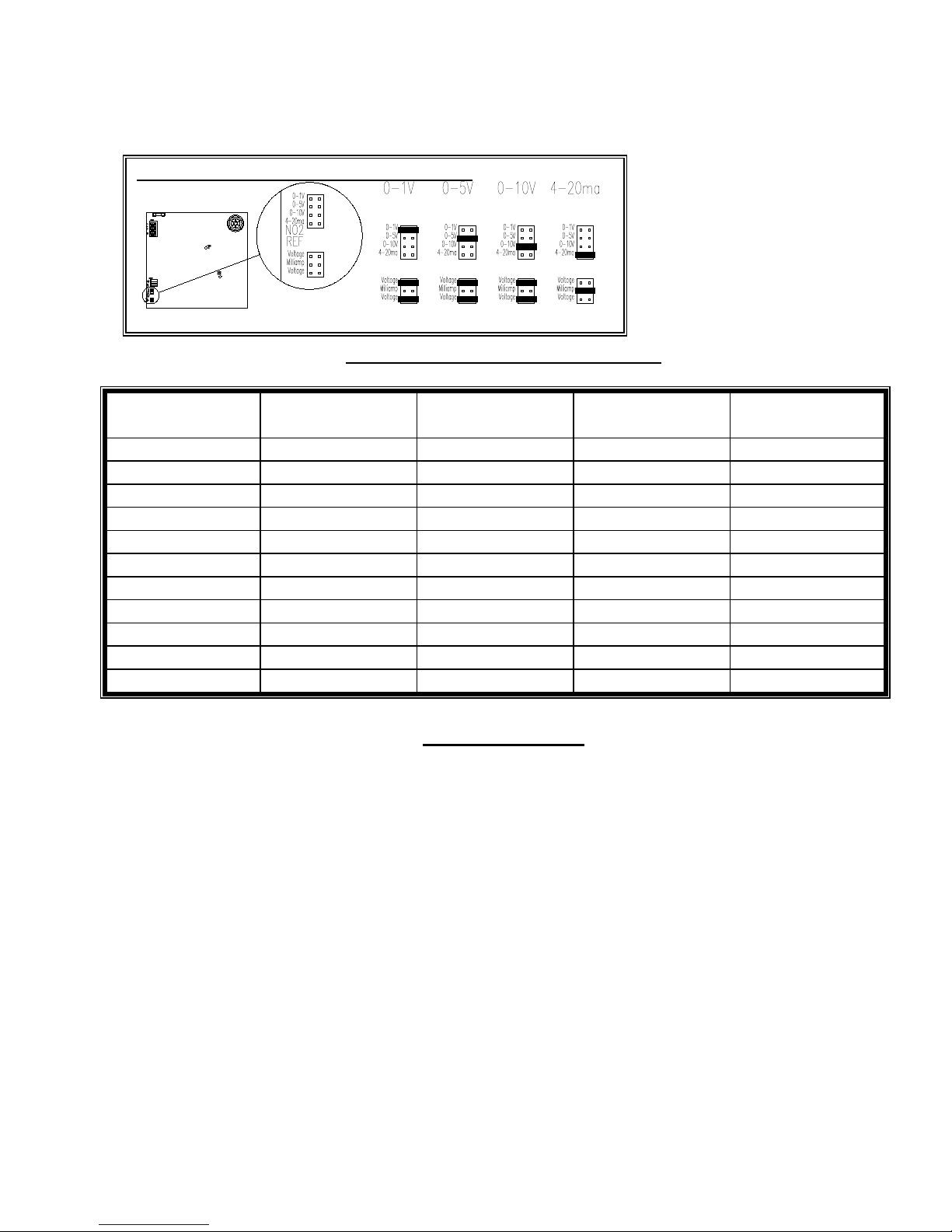
The output option is selected using a jumper and pin combination. See Figure #4 for location on the
transmitter board. To change the setting, turn off the power to the un it and remove the cover. Place
jumpers in the proper locations for the desired proportional output. Replace the cover and restore power
to the transmitter.
The proportional output is
Figure #4 Selection of Proportional Output Option
controlled by the concentration of
nitrogen dioxide (See Table #1).
If at any time a value of 0 maDC
or 0 VDC is measured at the
output, the gas transmitter has
had a power or sensor failure (See
5.0 Troubleshooting, Page 4).
TABLE #1 Proportional Output Values
Nitrogen Dioxide
PPM
4 – 20 maDC
Output Level
0 – 1 VDC
Output Level
0 – 5 VDC
Output Level
0.0 4.0 0.20 1.0 2.0
0.2 5.6 0.28 1.4 2.8
0.4 7.2 0.36 1.8 3.6
0.6 8.8 0.44 2.2 4.4
0.8 10.4 0.52 2.6 5.2
1.0 12.0 0.60 3.0 6.0
1.2 13.6 0.68 3.4 6.8
1.4 15.2 0.76 3.8 7.6
1.6 16.8 0.84 4.2 8.4
1.8 18.4 0.92 4.6 9.2
2.0 20.0 1.00 5.0 10.0
4.0 Specifications
Proportional Outputs: 4 – 20 maDC 250Ω Maximum
0 – 1 VDC 1000Ω Minimum
0 – 5 VDC 1000Ω Minimum
0 – 10 VDC 1000Ω Minimum
Proportional outputs are field selectable.
0 – 10 VDC
Output Level
Calibration: The main transmitter module should be re-calibrated every two years.
Contact the factory for re-calibration information and pricing.
Ratings: Input Power: 24 VAC, 50/60 Hz, 28 VA
Temperature: Storage: -50
Installation Category: II (local level, over-voltage transients less than 500 volts)
Indicators(LED Type): Green LED: Power ON
Humidity: 10% to 90% (Non-Condensing)
o
C to 120oC (-58oF to 248oF)
Operating: -15oC to 40oC (5oF to 104oF)
3
BULLETIN I-680
3-2-99
Page 4

Dimensions: 7 5/8”H x 9 1/8”W x 2 1/4”D
Weight: 4 pounds
Fuse Rating: Main Supply: 5x20MM, Time-Lag, 1.25 Amps
5.0 Troubleshooting
CAUTION:
Only qualified personnel should attempt to service this equipment. All power
sources must be disconnected before removing the cover of this transmitter.
1. Power LED not on: A. Check for 20.4-26.4 VAC at terminals T1 & T2 (see Figure #2,
Page 2).
B. Check circuit board fuse for continuity. If the fuse needs to be
replaced use only the rated fuse listed in the 4.0 Specifications
Section.
C. Consult the factory.
2. Sensor failure light is on: A. Remove sensor and reinstall.
B. Replace transmitter board (includes sensor and calibration).
C. Consult the factory.
3. For any other situation please consult the factory.
6.0 Accessories
Transformers: *
120 VAC to 24 VAC @ 36VA 36T120N1
120 VAC to 24 VAC @ 75VA 75T120N1
208-240 VAC to 24 VAC @ 36VA 36T240N1
208-240 VAC to 24 VAC @ 75VA 75T240N1
Other voltage levels are available upon request.
* Transformers supplied in a NEMA 1 enclosure intended for indoor use.
Sensor Re-calibration: Factory re-calibration of transmitter board including new sensor.
Contact the factory for complete information and pricing.
Brasch Manufacturing Company, Inc.
2310 Millpark Drive
Maryland Heights, MO 63043
BULLETIN I-680
3-2-99
(314)291-0440
fax: (314)291-0646
4
Page 5

Limited Warranty
Brasch Manufacturing Co., Inc warrants gas transmitters, gas detectors,
gas detector control panels and accessories for a period of one year
from the date of shipment against defects in material or workmanship.
Should any evidence of defects in material or workmanship occur
during the warranty period, Brasch Manufacturing Co., Inc will repair
or replace at its own discretion, without charge. The company shall not
be held responsible for any charges in connection with removal or
replacement of allegedly defective equipment, nor for incidental or
consequential damages.
Brasch Manufacturing Co., Inc warrants gas transmitters, gas transmitter control panels and accessories
for a period of one year from the date of shipment against defects in material or workmanship. Should
any evidence of defects in material or workmanship occur during the warranty period, Brasch
Manufacturing Co., Inc will repair or replace at its own discretion, without charge. The company shall
not be held responsible for any charges in connection with removal or replacement of allegedly defective
equipment, nor for incidental or consequential damages.
5
BULLETIN I-680
3-2-99
 Loading...