

Page 1
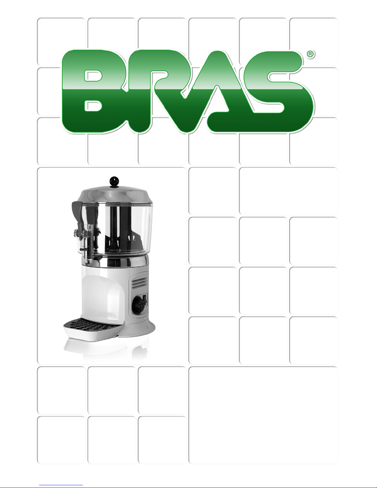
MANUALE D’ISTRUZIONI
OPERATOR’S MANUAL
CARNET D’INSTRUCTIONS
GEBRAUCHSANWEISUNG
MANUAL DE INSTRUCCIONES
SCIROCCO
Page 2

SCIROCCO
2
DICHIARAZIONE DI CONFORMITÀ CE
Noi Bras Internazionale spa - Via dei Pioppi 33 - 20090 Opera Milano - Italy dichiariamo, sotto la nostra responsabilità, che l’apparecchio
DISTRIBUTORE DI BEVANDE CALDE - Marca: BRAS INTERNAZIONALE S.p.A. - Fabbricante: BRAS INTERNAZIONALE S.p.A. Modelli: SCIROCCO - SCIROCCO GOLD - SCIROCCO SILVER 230V 50Hz sono conformi alle seguenti Normative:
In ottemperanza alle Direttive 2006/42/CE, 2006/95/CE, 2004/108/CE.
EC DECLARATION OF CONFORMITY
We Bras Internazionale spa - Via dei Pioppi 33 - 20090 Opera Milano - Italy declare, under our responsibility, that the apparatus HOT
DRINK DISPENSER - Trademark: BRAS INTERNAZIONALE S.p.A. - Manufacturer: BRAS INTERNAZIONALE S.p.A. - Model:
SCIROCCO - SCIROCCO GOLD - SCIROCCO SILVER 230V 50Hz are in conformity with the following Standards:
Following the provisions of the Directives 2006/42/CE, 2006/95/CE, 2004/108/CE.
DECLARATION DE CONFORMITE CE
Nous Bras Internazionale spa - Via dei Pioppi 33 - 20090 Opera Milano - Italy déclarons, sous notre responsabilité, que les appareil
DISTRIBUTEUR DE BOISSONS CHAUDES - Marque: BRAS INTERNAZIONALE S.p.A. - Constructeur: BRAS INTERNAZIONALE S.p.A.
- Modèle: SCIROCCO - SCIROCCO GOLD - SCIROCCO SILVER 230V 50Hz sont conformes aux Normes suivantes:
Conformément aux Directives 2006/42/CE, 2006/95/CE, 2004/108/CE.
EG-ÜBEREINSTIMMUNGSERKLÄRUNG
Wir Bras Internazionale spa - Via dei Pioppi 33 - 20090 Opera Milano - Italy erklären auf eigene Verantwortung, daß die Gerät
WARMEGETRÄNKE DISPENSER - Marke: BRAS INTERNAZIONALE S.p.A. - Hersteller: BRAS INTERNAZIONALE S.p.A. - Modell :
SCIROCCO - SCIROCCO GOLD - SCIROCCO SILVER 230V 50Hz mit den folgenden Normen übereinstimmen:
Gemäß den EWG-Richtlinien 2006/42/CE, 2006/95/CE, 2004/108/CE.
DECLARACIÓN DE CONFORMIDAD CE
Nosotros Bras Internazionale spa - Via dei Pioppi 33 - 20090 Opera Milano - Italy declararamos, bajo nuestra responsabilidad, que los
aparato DISTRIBUIDOR DE BEBIDAS CALIENTES - Marca: BRAS INTERNAZIONALE S.p.A. - Fabricante: BRAS INTERNAZIONALE
S.p.A. - Modelo: SCIROCCO - SCIROCCO GOLD - SCIROCCO SILVER 230V 50Hz responden con las siguientes Normativas:
En cumplimiento de las Normas 2006/42/CE, 2006/95/CE, 2004/108/CE.
-
-
-
-
-
EN ISO 12100-1 (2010)
EN ISO 12100-2 (2010)
EN60335-1 (2012)
EN60335-2-24 (2010)
EN60335-2-75 (2004)+A1(2005)+A11(2006)+A2(2008)+A12(2010)
-
-
-
-
EN62233:2008-11; EN62233:2009-04;
EN 55014 -1 (2006) + A1 (2009) + A2 (2011);
EN 55014-2 (1997) + A1 (2001) + A2 (2008)
EN 61000-3-2 (2006) + A1/A2 (2009); EN61000-3-3 (2008)
-
-
-
-
-
EN ISO 12100-1 (2010)
EN ISO 12100-2 (2010)
EN60335-1 (2012)
EN60335-2-24 (2010)
EN60335-2-75 (2004)+A1(2005)+A11(2006)+A2(2008)+A12(2010)
-
-
-
-
EN62233:2008-11; EN62233:2009-04;
EN 55014 -1 (2006) + A1 (2009) + A2 (2011);
EN 55014-2 (1997) + A1 (2001) + A2 (2008)
EN 61000-3-2 (2006) + A1/A2 (2009); EN61000-3-3 (2008)
-
-
-
-
-
EN ISO 12100-1 (2010)
EN ISO 12100-2 (2010)
EN60335-1 (2012)
EN60335-2-24 (2010)
EN60335-2-75 (2004)+A1(2005)+A11(2006)+A2(2008)+A12(2010)
-
-
-
-
EN62233:2008-11; EN62233:2009-04;
EN 55014 -1 (2006) + A1 (2009) + A2 (2011);
EN 55014-2 (1997) + A1 (2001) + A2 (2008)
EN 61000-3-2 (2006) + A1/A2 (2009); EN61000-3-3 (2008)
-
-
-
-
-
EN ISO 12100-1 (2010)
EN ISO 12100-2 (2010)
EN60335-1 (2012)
EN60335-2-24 (2010)
EN60335-2-75 (2004)+A1(2005)+A11(2006)+A2(2008)+A12(2010)
-
-
-
-
EN62233:2008-11; EN62233:2009-04;
EN 55014 -1 (2006) + A1 (2009) + A2 (2011);
EN 55014-2 (1997) + A1 (2001) + A2 (2008)
EN 61000-3-2 (2006) + A1/A2 (2009); EN61000-3-3 (2008)
-
-
-
-
-
EN ISO 12100-1 (2010)
EN ISO 12100-2 (2010)
EN60335-1 (2012)
EN60335-2-24 (2010)
EN60335-2-75 (2004)+A1(2005)+A11(2006)+A2(2008)+A12(2010)
-
-
-
-
EN62233:2008-11; EN62233:2009-04;
EN 55014 -1 (2006) + A1 (2009) + A2 (2011);
EN 55014-2 (1997) + A1 (2001) + A2 (2008)
EN 61000-3-2 (2006) + A1/A2 (2009); EN61000-3-3 (2008)
vedere targa dati sulla macchina
see data plate on the machine
voir la plaque sur l’appareil
siehe Dispenser Typenschild
ver la placa del distribuidor
Bras Internazionale spa
L’Amministratore Delegato
(luogo ed anno di prod. - place and mfr. year - lieu et an de production
Produktionsort und Produktionsjahr - lugar y año de producción)
Page 3
3
1. L'apparecchio è garantito per un periodo di dodici mesi dalla data di acquisto.
Tale data viene certificata dalla ricevuta e/o fattura fiscale e/o da un documento
attestante l'avvenuta consegna dell'apparecchio all'acquirente.
2. Per garanzia si intende la sostituzione o riparazione gratuita delle parti componenti l'apparecchio riconosciute difettose all'origine, per vizi di fabbricazione a
condizione che: A- il difetto di funzionamento dell'apparecchio sia stato -a pena
di decadenza- denunziato per iscritto dall'acquirente al produttore entro otto giorni dalla scoperta del difetto stesso; B-ove l'acquirente abbia diritto alla garanzia,
sarà dovere di Bras Internazionale s.p.a. provvedere -a sua insindacabile discrezione- alla sostituzione integrale dell'apparecchio, ovvero alla sostituzione o riparazione delle sole parti di esso riconosciute difettose all'origine, per vizi di
fabbricazione.
3. Sono escluse dalla garanzia le parti dell'apparecchio aventi funzione estetica e/
o ornamentale, nonché le parti che dovessero risultare difettose a causa -o per effetto- di circostanze non connesse a vizi di fabbricazione ovvero a negligenza, imperizia o trascuratezza nell'uso, installazione errata o, comunque, difforme
rispetto le istruzioni fornite dal produttore, manutenzione errata o eseguita da personale non autorizzato da Bras Internazionale s.p.a., o, comunque, effettuata in
modo difforme rispetto alle istruzioni fornite dal produttore, (ivi) trasporto eseguito in modo inidoneo o, comunque, con modalità differenti rispetto quelle indicate dal produttore; sono altresì esclusi dalle prestazioni in garanzia gli interventi
tecnici inerenti l'installazione e l'allacciamento agli impianti di alimentazione
elettrica o idrica.
4. E' esclusa dalla garanzia la responsabilità del produttore per l'ipotesi in cui l'apparecchio determini la distruzione o il deterioramento di una cosa diversa dall'apparecchio stesso; è, inoltre, esclusa la responsabilità del produttore per eventuali
danni che possano, direttamente o indirettamente, derivare a persone e/o cose per
effetto della -e/o in correlazione alla- mancata o inesatta osservanza di tutte le prescrizioni indicate nel manuale di istruzioni allegato all'apparecchio; nelle ipotesi
in cui il produttore sia tenuto a rispondere dei danni subiti dall'acquirente, il risarcimento non potrà in ogni caso comportare, a carico di Bras Internazionale s.p.a.,
un esborso superiore al prezzo versato dall'acquirente per l'acquisto del prodotto.
5. Sono escluse dalla garanzia anche tutte le spese di trasporto.
6. L'intervento di riparazione dell'apparecchio deve essere effettuato presso Bras
Internazionale s.p.a., ovvero presso uno dei laboratori autorizzati dalla medesima;
le spese di trasporto, ed i rischi ad esso connessi, sono interamente a carico
dell'acquirente; ove l'intervento di riparazione sia effettuato a domicilio, l'acquirente sarà tenuto a corrispondere il diritto fisso di chiamata in vigore presso il produttore alla data dell'intervento.
7. Trascorsi dodici mesi dall'acquisto, decade il diritto di garanzia e l'assistenza
verrà esplicata addebitando, oltre alle spese di manodopera, anche il costo delle
parti sostituite e quelle di trasporto.
8. Sono esclusi la sostituzione dell'apparecchio ed il prolungamento della garanzia a seguito di intervenuto guasto.
9. E' escluso dalla garanzia l'apparecchio la cui targa di identificazione risulti manomessa, asportata o comunque in condizioni tali da non rendere possibile l'identificazione certa dell'apparecchio stesso.
10. Tale garanzia è valida solo nel territorio in cui l'acquirente ha la propria sede
legale alla data dell'acquisto dell'apparecchio.
ITALIANO
4
ENGLISH
11
FRANCAIS
17
DEUTSCH
24
ESPAÑOL
33
GARANZIA
Ai sensi dell’art.13 del Decreto Legislativo 25 Luglio 2005, n.151 “Attuazione delle Direttive 2002/95 /CE, 2002/96/CE e 2003/108/CE, relative alla
riduzione dell’uso di sostanze pericolose nelle apparecchiature elettriche
ed elettroniche, nonchè allo smaltimento dei rifiuti”.
Il simbolo del cassonetto barrato riportato sull’apparecchiatura o sulla sua
confezione indica che il prodotto alla fine della propria vita utile deve essere raccolto separatamente dagli altri rifiuti.
La raccolta differenziata della presente apparecchiatura giunta a fine vita è organizzata e gestita dal produttore. L’utente che vorrà disfarsi della presente apparecchiatura dovrà quindi contattare il produttore e seguire il sistema che questo ha
adottato per consentire la raccolta separata dell’apparecchiatura giunta a fine vita.
L’adeguata raccolta differenziata per l’avvio successivo dell’apparecchiatura dismessa al riciclaggio, al trattamento e allo smaltimento ambientalmente compatibile contribuisce ad evitare possibili effetti negativi sull’ambiente e sulla salute e
favorisce il reimpiego e/o riciclo dei materiali di cui è composta l’apparecchiatura.
Lo smaltimento abusivo del prodot to da parte del detentore comporta l’applicazione
delle sanzioni amministrative previste dalla normativa vigente.
Pursuant to the European Directives 2002/95/EC, 2002/96/EC and 2003/
108/EC, on restricting the use of hazardous substances in electric and
electronic equipment and on the disposal of waste material.
The crossed out wheelie bin symbol applied to equipment or packaging
means that the product should be collected separately from other types of
waste at the end of its useful life.
The separate collection of equipment that has reached the end of its life cycle is
organised and managed by the manufacturer. A user that wishes to dispose of this
product should therefore contact the manufacturer and follow the instructions given
with respect to the separate collection of obsolete equipment.
Correct separate collection and the subsequent recycling, treatment and environmentally compatible disposal of discarded equipment is of aid in avoiding possible
negative effects for the environment and people's health and facilitates the re-use
or recycling of the materials of which the equipment is made.
Illegal disposal of this product on part of the owner will give way to the application
of administrative fines as provided by current laws.
Conformément aux Directives européennes 2002/95/CE, 2002/96/CE et
2003/108/CE, relatives à la réduction de l'utilisation de substances dan-
gereuses dans les appareils électriques et électroniques, ainsi qu'à l'élim-
ination conforme et au recyclage des déchets.
Le symbole de la poubelle barrée indiqué sur l'appareil ou sur sa boîte in-
dique qu'à la fin de sa vie utile ce produit doit être éliminé séparément des
autres déchets et conformément aux lois en vigueur en la matière.
La collecte différenciée de cet appareil à la fin de sa vie utile, est o rganisée et gérée
par le producteur. Par conséquent, lorsque l'utilisateur souhaitera jeter cet appareil
il devra contacter le producteur et respecter le système que ce dernier aura mis en
place pour réaliser la collecte différenciée des appareils arrivés à la fin de leur vie
utile.
La collecte différenciée correctement effectuée, suivie de l'envoi des appareils
éliminés au recyclage, avec traitement et élimination des déchets dans le plus strict
respect de l'environnement, est une procédure fondamentale qui contribue à éviter
les possibles effets négatifs sur notre environnement et sur notre santé, et qui favorise la réutilisation et/ou le recyclage des matériaux qui composent ces appareils.
L'élimination abusive de ce produit par son propriétaire comporte l'application de
sanctions administratives sévères, prévues par la réglementation en vigueur.
Laut EG-Richtlinien 2002/95/EG, 2002/96/EG und 2003/108/EG zur Beschränkung der Verwendung gefährlicher Stoffe in elektronischen
Geräten sowie zur Abfallentsorgung.
Das Symbol des durchgestrichene n Abfallcontainers auf der Packung gibt
an, dass das Produkt zum Ende seiner Lebensdauer getrennt von den an-
deren Abfällen entsorgt werden muss.
Die getrennte Abfallsammlung dieses Geräts am Ende seiner Lebensdauer wird
vom Hersteller organisiert und verwaltet. Der Nutzer, der das Gerät entsorgen
möchte, muss sich daher mit dem Hersteller in Verbindung setzen und das System
befolgen, das dieser angewendet hat, um das Altgerät der getrennten Abfallsammlung zuzuführen.
Eine angemessene Mülltrennung, die das Altgerät zur Wiederverwertung und
umweltverträglichen Entsorgung führt, trägt dazu bei, mögliche negative Auswirkungen auf die Umwelt und die Gesundheit zu vermeiden und fördert die Wiederverwendung bzw. das Recycling der Materialien, aus denen das Gerät besteht.
Die unerlaubte Entsorgung des Produkts durch den Benutzer zieht die Anwendung
der von der geltenden Richtlinie vorgesehenen Ordnungsstrafen nach sich.
En virtud de las Directivas europeas 2002/95/CE, 2002/96/CE y 2003/
108/ CE, relativas a la reducción del uso de sustancias peligrosas en los
aparatos eléctricos y electrónicos, así como a la eliminación de residuos.
El símbolo del contenedor tachado que aparece impreso sobre el aparato
o sobre su embalaje indica que al finalizar la vida útil del producto éste
nunca debe depositarse junto al resto de residuos.
La recogida selectiva de este equipo cuando llegue al final de su vida útil la gestionará y organizará el fabricante. El usuario que desee deshacerse de este equipo
deberá ponerse en contacto con el fabricante y seguir el sistema que éste haya
adoptado para permitir la recogida selectiva del aparato que haya llegado al final
de su vida útil.
La recogida selectiva adecuada para el posterior reciclaje, tratamiento y eliminación del equipo inservible, compatible con el medio ambiente, contribuye a evitar
posibles efectos negativos para el medio ambiente y para la salud y favorece la
reutilización y/o el reciclaje de los materiales de los que está compuesto el equipo.
La eliminación inadecuada del producto por parte de su propietario comportará la
aplicación de las sanciones administrativas previstas por la normativa vigente.
Page 4

SCIROCCO
4
ITALIANO
1 CARATTERISTICHE TECNICHE
E’ riservato il diritto di modifica senza preavviso.
2 INTRODUZIONE
E’ necessario leggere attentamente questo libretto di istruzioni allo scopo di conoscere tutte le caratteristiche del distributore.
Come tutti i prodotti meccanici, anche questo distributore richiede pulizia e cura. Il suo buon funzionamento inoltre può essere compromesso da
eventuali errori compiuti dall'operatore durante le
fasi di smontaggio e pulizia. Per questo motivo è
importante che le procedure di smontaggio, lavaggio, sanitizzazione e rimontaggio, essendo
operazioni giornaliere,
siano conosciute senza
possibilità di errore a chi utilizza il distributore.
3 INSTALLAZIONE
1 Estrarre il distributore dall’imballo, che è con-
sigliabile conservare per future necessità.
2 Controllare che il distributore non abbia
subito danni da trasporto. In caso contrario, provvedere immediatamente ad effettuare il reclamo
presso il vettore.
3 Appoggiare il distributore su un banco in
grado di sostenerne il peso, anche a carico completo.
4 Prima di collegare elettricamente il distribu-
tore controllare che la tensione di rete sia quella
corretta indicata in targa. Collegare il distributore
a una rete monofase, servendosi di una presa
completa di messa a terra secondo quanto stabilito dalle norme vigenti. Nel caso la disconnessione dell`apparecchio dalla rete elettrica sia
affidata ad un interruttore onnipolare, tale interruttore deve garantire una distanza di apertura
dei contatti che consenta la disconnessione completa nelle condizioni della categoria di sovratensione III. Non usare prolunghe per collegare
elettricamente l'apparecchio.
5 Il distributore non esce prelavato e sanitiz-
zato dalla fabbrica. Prima dell’uso esso deve
essere smontato, lavato e sanitizzato seguendo
quanto previsto nelle presenti istruzioni al capitolo 7 PULIZIA.
Scirocco
Contenitori trasparenti smontabili n 1
Capacità singolo contenitore, circa l 5
Dimensioni:
larghezza cm 24
profondità cm 32
altezza cm 49
Peso netto, circa kg 6
Peso lordo, circa kg 7
Termostati regolabili n 1
Livello di rumorosità inferiore a 70 dB (A)
IMPORTANTE
Caratteristiche elettriche: leggere i dati
riportati sulla targa di ogni singolo distributore; questa è situata sotto il distributore
stesso. I numeri di matricola degli apparecchi sono preceduti dal simbolo #. I dati
riportati sulla targa sono sempre quelli a
cui fare riferimento.
ATTENZIONE
Assicurarsi che l’apparecchio sia correttamente collegato a terra; in caso contrario è
possibile causare shock elettrici alle persone o danneggiare il distributore.
Page 5

5
4 PER UN FUNZIONAMENTO
SICURO E CORRETTO
1 Non usare il distributore prima di aver letto il
presente libretto d’istruzioni.
2 Non usare il distributore se non corretta-
mente collegato a terra.
3 Non usare prolunghe per collegare elettrica-
mente il distributore.
4 Non mettere in funzione il distributore se
questo non è chiuso e bloccato con viti.
5 Non introdurre dita o oggetti nelle fessure di
raffreddamento e nell’apertura del rubinetto.
6 Non rimuovere il contenitore quando la mac-
china è in funzione.
7 Apparecchio non idoneo per il funziona-
mento all'esterno.
8 Apparecchio non idoneo all'istallazione in
zone nelle quali può essere utilizzato un getto
d'acqua.
9 Per la pulizia, non utilizzare un getto
d'acqua.
10 Per un corretto funzionamento, la tempera-
tura ambiente deve essere compresa tra +5° e
+35°C.
5 ISTRUZIONI PER L’USO
1 Lavare e sanitizzare il distributore prima di
utilizzarlo seguendo quanto previsto nelle presenti istruzioni al capitolo 7 PULIZIA.
2 Riempire il contenitore con il prodotto desi-
derato, preparato secondo le istruzioni del produttore.
3 Montare il coperchio sopra il contenitore
accertandosi che questo sia posizionato correttamente.
4 Agire sui comandi (vedere capitolo
5.1 DESCRIZIONE DEI COMANDI).
5 Il distributore deve sempre funzionare con il
coperchio montato al fine di prevenire un’eventuale contaminazione del prodotto.
6 Il distributore deve funzionare ininterrotta-
mente: il riscaldamento si arresterà automaticamente quando il prodotto sarà pronto per la
distribuzione. Il dispositivo di agitazione continuerà a funzionare.
7 Il distributore è dotato di contenitore a fondo
chiuso rimovibile al fine di agevolare le operazioni di pulizia e sanitizzazione.
IMPORTANTE
Questo apparecchio può essere utilizzato
da bambini di età superiore agli 8 anni e da
persone con capacità fisiche, mentali o
sensoriali ridotte o prive di esperienza solo
in presenza di un adulto che ne garantisca
la sorveglianza o che fornisca istruzioni
relative all'uso sicuro del prodotto e ai possibili rischi. I bambini non devono giocare
con l'apparecchio. Le operazioni di pulizia e
manutenzione non devono essere effettuate da bambini non sorvegliati.
ATTENZIONE
Al fine di evitare scottature non rimuovere
il contenitore fino a quando la piastra
riscaldante non è fredda.
ATTENZIONE
Non rimuovere il contenitore dal distributore quando questo contiene prodotto
caldo.
IMPORTANTE
L’apparecchio deve essere installato su di
un piano orizzontale.
ATTENZIONE
Se il cavo di alimentazione è danneggiato,
esso deve essere sostituito dal costruttore
o dal suo servizio assistenza tecnica o ,
comunque, da una persona con qualifica
similare, in modo da prevenire ogni rischio.
Page 6
SCIROCCO
6
ITALIANO
6 DESCRIZIONE DEI COMANDI
Il distributore è provvisto di un interruttore generale le cui funzioni sono le seguenti:
Il distributore è poi dotato di un termostato, posto
sul lato destro, per la regolazione della temperatura del prodotto.
6. 1 SUGGERIMENTI
Preparazione della cioccolata: seguendo il metodo artigianale, stemperare bene il cacao in una
casseruola prima di versarlo nel contenitore del
distributore. Usando prodotti istantanei confezionati attenersi invece alle istruzioni del fabbricante. Con questo genere di prodotti la miscelazione
può essere effettuata direttamente nel contenitore.
Azionare quindi il distributore mettendo l’interruttore in posizione I. Nella versione manuale ruotare la manopola del termostato fino alla posizione
90 °C ottenendo così la temperatura di cottura del
prodotto. Quando la cioccolata sarà pronta abbassare la temperatura al valore desiderato per la
distribuzione agendo sulla manopola del termo-
stato.
7 PULIZIA
Pulizia e lavaggio sono fondamentali per garantire la perfetta conservazione del gusto della bevanda e la massima efficienza del vostro
distributore.
Le procedure descritte nel seguito
devono essere considerate di carattere generale
e possono variare per effetto della regolamentazione sanitaria vigente.
Prima dello smontaggio per il lavaggio il distributore deve essere svuotato del prodotto.
7. 1 SMONTAGGIO
1 Svuotare il contenitore e togliere il coperchio.
2 Sfilare il mescolatore dall’albero centrale.
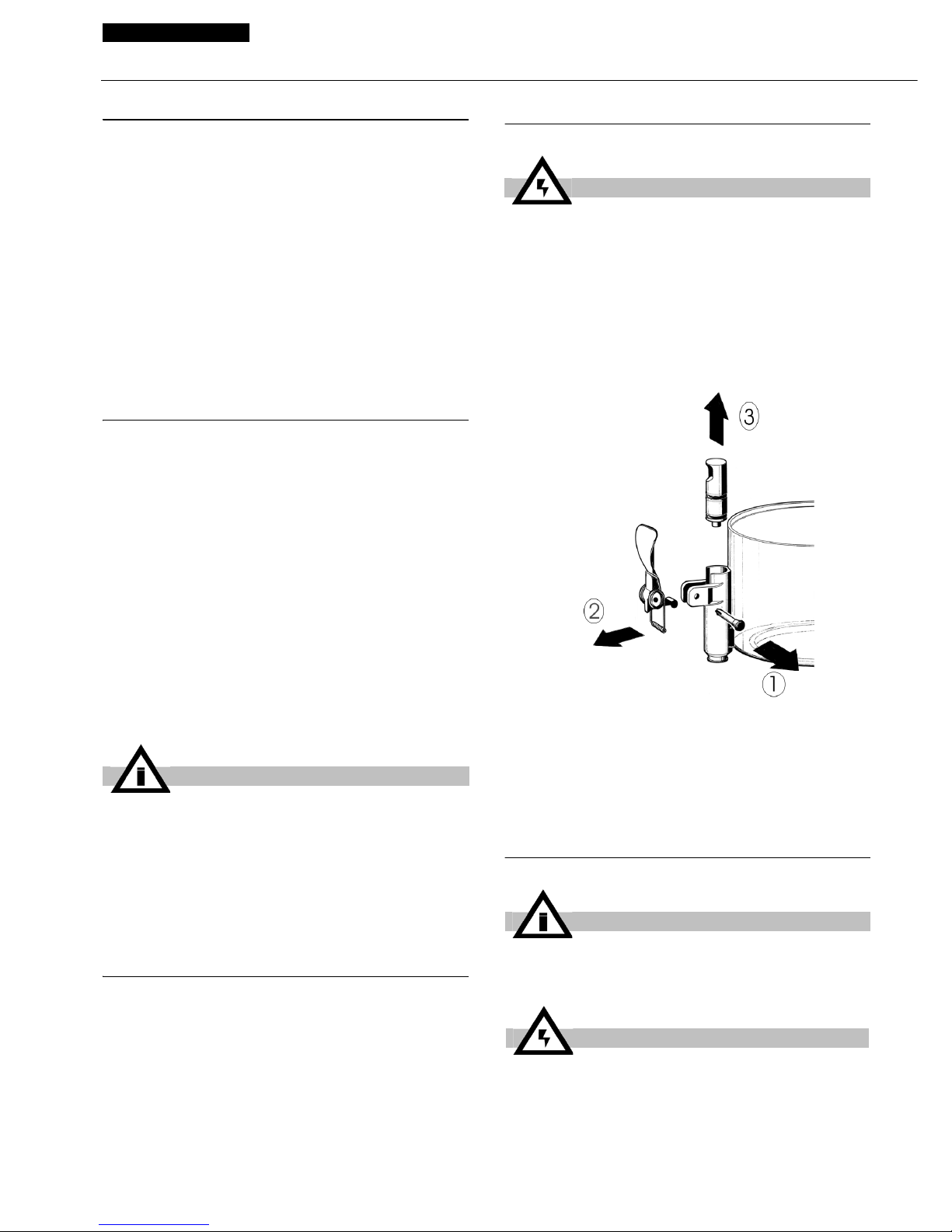
3 Disassemblare il rubinetto con la sequenza
indicata (vedere figura 1).
figura 1
4 Togliere il contenitore, sollevandolo verso
l’alto.
5 Sfilare il cassetto raccogligocce e svuotarlo.
7. 2 LAVAGGIO
Posizione 0 : il distributore è spento.
Posizione I : funziona sia il dispositivo di agi-
tazione che il riscaldamento.
IMPORTANTE
Prima di spegnere completamente il distributore (interruttore in posizione 0), portare
il termostato nella posizione di minima temperatura ed attendere che il prodotto si raffreddi. Ciò evita che il prodotto stesso, (se
non agitato) si incolli sulla piastra riscaldante.
ATTENZIONE
Prima di procedere allo smontaggio di qualsiasi componente disconnettere sempre
elettricamente l’apparecchio togliendo la
spina dalla presa.
IMPORTANTE
Non lavare alcun componente della macchina in lavastoviglie.
ATTENZIONE
Prima di qualsiasi intervento di pulizia
disconnettere sempre elettricamente il
distributore estraendo la spina dalla presa.
Page 7
7
1 Preparare in una bacinella circa quattro litri
di acqua calda (45-60°C) e detersivo specifico
rispettando con attenzione le prescrizioni del fabbricante; una soluzione troppo concentrata può
infatti causare danni alle parti da lavare, mentre
una troppo diluita può non detergere a suffi-
cienza. Non usare detersivi abrasivi.
2 Usare una spazzola adatta e lavare accura-
tamente con la soluzione detergente tutte le parti
a contatto con la bevanda.
3 Risciacquare tutte le parti lavate con acqua
corrente.
7. 3 SANITIZZAZIONE
La sanitizzazione deve essere eseguita immediatamente prima di mettere in funzione il distributore, ogni giorno; evitare che questo
rimanga inattivo per lungo tempo dopo la sanitizzazione.
1 Prima di iniziare le procedure descritte nel
seguito lavarsi le mani con un sapone antibatterico.
2 Preparare in una bacinella circa quattro litri
di soluzione di acqua calda (45-60°C) e prodotto
sanitizzante approvato dalle autorità del vostro
paese rispettando le specifiche del produttore. In
mancanza di un prodotto sanitizzante specifico,
preparare una soluzione di acqua e ipoclorito di
sodio (varechina) in proporzione di 1 cucchiaio
ogni 2 litri di acqua.
3 Immergere nella soluzione tutte le parti da
sanitizzare per il tempo indicato dal fabbricante
del prodotto.
4 Fare asciugare all'aria, su una superficie
pulita, le parti sanitizzate.
5 Asciugare le parti esterne del distributore
senza usare panni abrasivi.
7. 4 RIMONTAGGIO
1 Inserire cassetto raccogligocce e griglia nella
sua sede.
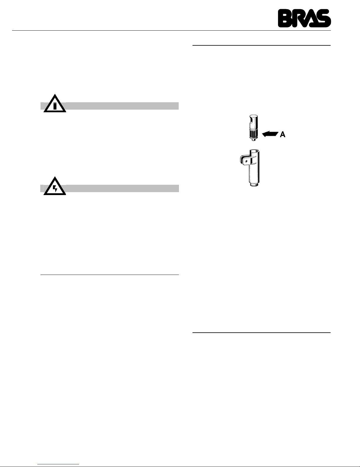
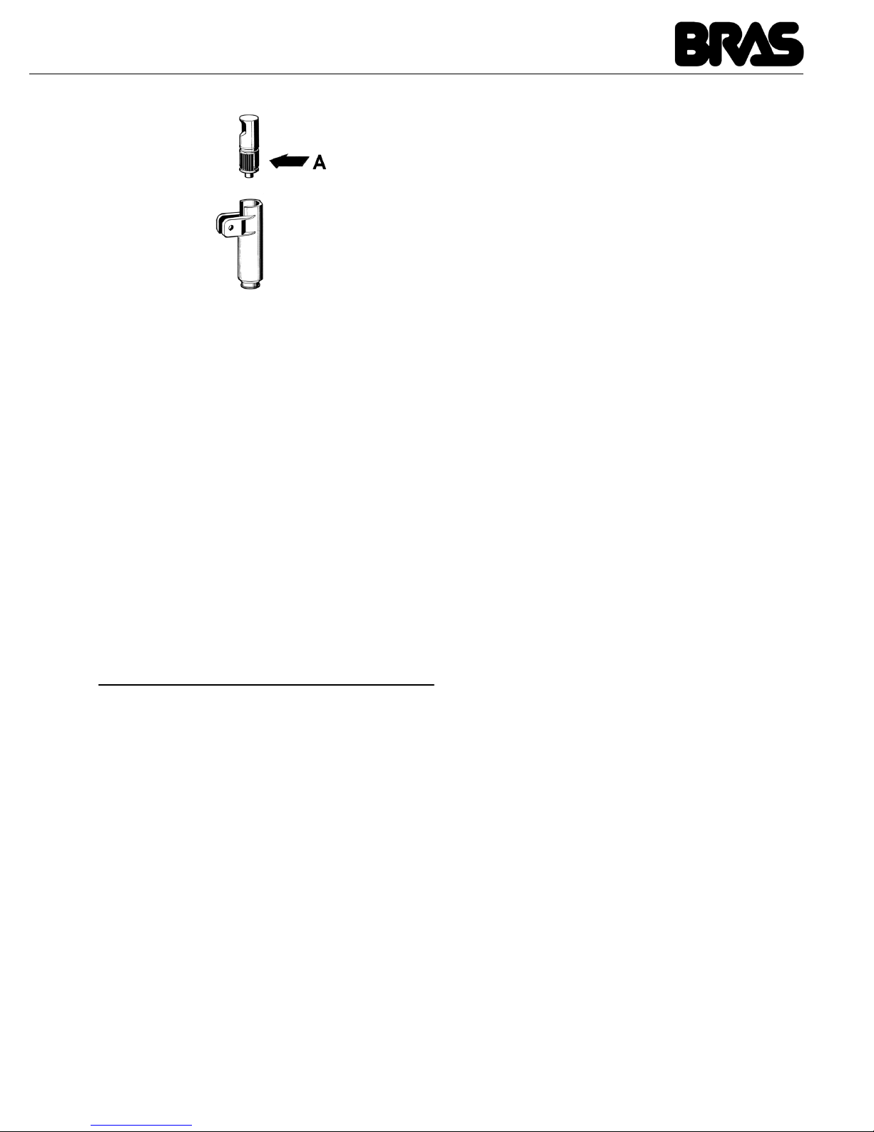
2 Lubrificare il pistone rubinetto (nella zona A
indicata in figura 2) utilizzando esclusivamente
grasso per uso alimentare.
figura 2
3 Riassemblare il rubinetto sul contenitore con
sequenza inversa rispetto a quanto fatto per lo
smontaggio (vedere figura 1).
4 Montare il contenitore infilando l’albero cen-
trale nell’apposita sede.
5 Inserire il mescolatore nell’albero centrale.
6 Posizionare il coperchio sul contenitore.
8 MANUTENZIONE
1 Ogni giorno: controllare il distributore e veri-
ficare che non ci siano perdite di prodotto dalle
guarnizioni. Se si notano perdite, controllare
prima di tutto che il distributore sia correttamente
montato, quindi verificare che le guarnizioni non
necessitino di lubrificazione e infine che non
siano difettose o usurate; in tal caso sostituirle
con ricambi originali del fabbricante.
2 Al fine di prevenire danni al distributore le
parti in plastica devono essere lubrificate solo
con il grasso fornito dal fabbricante o con altro
grasso compatibile con policarbonato.
IMPORTANTE
Al fine di evitare danni al distributore utilizzare solo detersivi compatibili con le parti
in plastica.
ATTENZIONE
Durante il lavaggio del distributore non
usare eccessiva quantità di acqua in vicinanza dei componenti elettrici; in caso contrario è possibile causare shock elettrici o
danneggiare il distributore.
Page 8

SCIROCCO
8
ITALIANO
POSSIBILI INCONVENIENTI E LORO RIMEDI
PROBLEMA CAUSA RIMEDIO
Mescolatore non ruota Innesto su albero di trascina-
mento non effettuato correttamente
Verificare la corretta posizione di funzionamento
Innesto su albero di trascinamento rotto
Sostituire mescolatore e/o
albero di trascinamento
Motoriduttore non funzionante Vedere “Motoriduttore non
ruota”
Conduttori elettrici scollegati o
interrotti
Collegare o sostituire i
conduttori elettrici
Densità del prodotto eccessiva Diluire maggiormante il
prodotto
Motoriduttore non ruota Motore surriscaldato : inter-
vento del “Protettore termico”
Controllare il voltaggio della
presa di corrente
Controllare la viscosità del
prodotto
Controllare la ventilazione
(alette dei pannelli laterali
ostruite o parte inferiore del
distributore ostruito)
Avvolgimento dello statore
bruciato o interrotto
Sostituire il motore
Rotore disassato Controllare l’allineamento
dei cuscinetti del rotore
Ingranaggi nella scatola del
riduttore danneggiati o consumati
Sostituire il motore
Perdite di bevanda dal
contenitore
Guarnizione del contenitore
rotta o consumata
Sostituire la guarnizione
O-Ring del pistone rubinetto
rotto o consumato
Sostituire gli O-Ring del pistone
Pistone rubinetto non in posizione di chiusura
Controllare la leva o la molla del rubinetto e sostituire
la parte usurata
Page 9
9
La resistenza non scalda Resistenza bruciata Sostituire la resistenza
Termolimitatore di sicurezza
bruciato
vedere “temolimitatore di
sicurezza bruciato”
Termolimitatore di sicurezza bruciato
Termolimitatore difettoso Sostituirlo con uno integro
Non riesco ad ottenere un
prodotto sufficientemente denso
Il termostato di servizio (posto
a lato del distributore) è
regolato a una temperatura
troppo bassa
Regolarlo alla temperatura
opportuna
Prodotto eccessivamente
diluito
Aumentare concentrazione
del prodotto
Non riesco a ottenere un
prodotto sufficientemente caldo
Il termostato di servizio (posto
a lato del distributore) è
regolato ad una temperatura
troppo bassa
Regolarlo alla temperatura
opportuna
Non c’è contatto tra fondo
vasca e resistenza
Posizionare in maniera
corretta la vasca sulla
resistenza
PROBLEMA CAUSA RIMEDIO
Page 10
10
SCIROCCO
ENGLISH
1 TECHNICAL CHARACTERISTICS
The manufacturer reserves the right to make
changes without any prior notification.
2 INTRODUCTION
It is necessary to read this instruction manual
carefully to know the specifications of the
dispenser. As all mechanical products, this unit
requires cleaning and maintenance. Its working
order can be compromised by possible errors
made by the operator during disassembly and
cleaning. For this reason it is important that the
staff in charge of the dispenser is qualified to
carry out the day to day operations, which are
dismantling, cleaning, sterilisation and
reassembly.
3 INSTALLATION
1 Remove the dispenser from the packaging.
(This should be kept for any future requirement)
2 Check the dispenser has not been damaged
during transport. The forwarding agent must be
notified immediately of any claim.
3 Install the dispenser on a counter top that will
support its weight, even with a full load.
4 Before connecting the dispenser electrically
check that the voltage (in the network) is as
shown on the data plate. Plug the unit into a
grounded, protected single phase electrical
supply according to the applicable electrical
codes and the specifications of your machine.
The electrical disconnect switch shall have a
contact separation in all poles , providing full
disconnection under over voltage category III
conditions. not use extension cords to connect
the unit electrically.
5 The dispenser does not leave the factory
presanitized and sanitized. Prior to use it must be
disassembled, cleaned and sanitized according
to the instructions in chapter 7 CLEANING AND
SANITIZING PROCEDURES.
4 TO OPERATE PROPERLY AND
SAFELY
1 Read the instruction booklet before using the
dispenser.
2 Use the dispenser only if it is grounded
correctly.
3 Do not use extension cords to connect the
dispenser electrically.
4 Do not operate the dispenser if it is not
closed and blocked with screws.
5 Do not place fingers or objects in the cooling
fissures and faucet outlet panels louvers.
6 Do not remove the container when the unit is
Scirocco
Transparent removable bowls n 1
Capacity of each bowl, approx. l 5
Dimensions:
width cm 24
depth cm 32
height cm 49
Net weight, approx. kg 6
Gross weight, approx. kg 7
Adjustable thermostats n 1
Noise level lower than 70 dB (A)
IMPORTANT
Electric specifications: read the information on the data plate of each single dispenser, situated on the underside. The serial
number of the units is preceded by #
ATTENTION
Ensure that the unit is grounded correctly;
if not it may cause electric shock to persons or damage the dispenser.
IMPORTANT
This appliance can be used by children
aged from 8 years and above and persons
with reduced physical, sensory or mental
capabilities or lack of experience and knowledge if they have been given supervision
or instruction concerning use of the
appliance in a safe way and understand the
hazards involved. Children shall not play
with the appliance. Cleaning and user maintenance shall not be made by children
without supervision.
Page 11
11
in operation.
7 This unit is not meant to be used outside.
8 This unit is not to be installed in areas
subject to water-spouts..
9 Do not use water-jets to clean the unit.
10 This unit can work in a room temperature
range between +5° and +35°C.
5 OPERATING PROCEDURES
1 Clean and sanitized the dispenser prior to
use following the instructions in chapter 7
CLEANING AND SANITIZING PROCEDURES.
2 Fill the bowl with the product, prepared
according to the instructions of the manufacturer.
3 Install the cover above the container making
sure that it is placed correctly.
4 Set the control switch (see charter 5.1.
COMMAND DESCRIPTIONS)
5 The dispenser should always operate with
the cover installed in order to prevent possible
contamination of the product.
6 The dispenser must run uninterruptedly;
heating will stop automatically when the product
is ready for dispensing. The mixing device will
continue to operate.
7 The dispenser is supplied with a container
with a closed removable bottom to facilitate
cleaning and sterilisation.
5. 1 DESCRIPTION OF CONTROLS
The dispenser is equipped with a general switch
whose functions are:
The dispenser is equipped with a thermostat, on
the right side, to adjust the temperature of the
product.
6 OPERATION HELPFUL HINTS
Preparation hot chocolate: preparation following
the traditional artisan method, mix the cocoa with
milk or water well in a pan before pouring it into
the bowl. Follow the instructions of the
manufacturer if using packaged instantaneous
products. It is possible to mix these directly in the
container.
Activate the dispenser turning the switch to
position 1. In the normal version turn the
thermostat knob to 90°C to obtain the cooking
temperature of the product. When the hot
chocolate is ready lower the temperature to the
value required for dispensing turning the
thermostat knob.
7 CLEANING AND SANITIZING
PROCEDURES
Cleaning and sanitizing are essential to maintain
perfect taste and maximum efficiency from your
dispenser. The procedures described below are
general and can vary due to the sanitary
regulations of the local health authorized.
The product must be taken out of the dispenser
before it is disassembled for cleaning.
ATTENTION
Do not remove the container until the hot
plate is cold.
ATTENTION
Do not remove the container from the
dispenser when it contains hot products.
IMPORTANT
Place the unit on an horizontal surface.
ATTENTION
In case of damages, the power cord must
be replaced by qualified personnel only in
order to prevent any shock hazard.
Position 0 : power is turned off
Position I : mixer and heating device in wor-
king order
IMPORTANT
Before switching off the dispenser completely (switch at position 0), bring the thermostat to the lowest temperature and wait for
the product to cool down. This stops the
product (if not agitated) from sticking to the
hot plate
Page 12
12
SCIROCCO
ENGLISH
7. 1 DISASSEMBLY
1 Empty the bowl and remove the lid
2 Remove the mixer from the central shaft
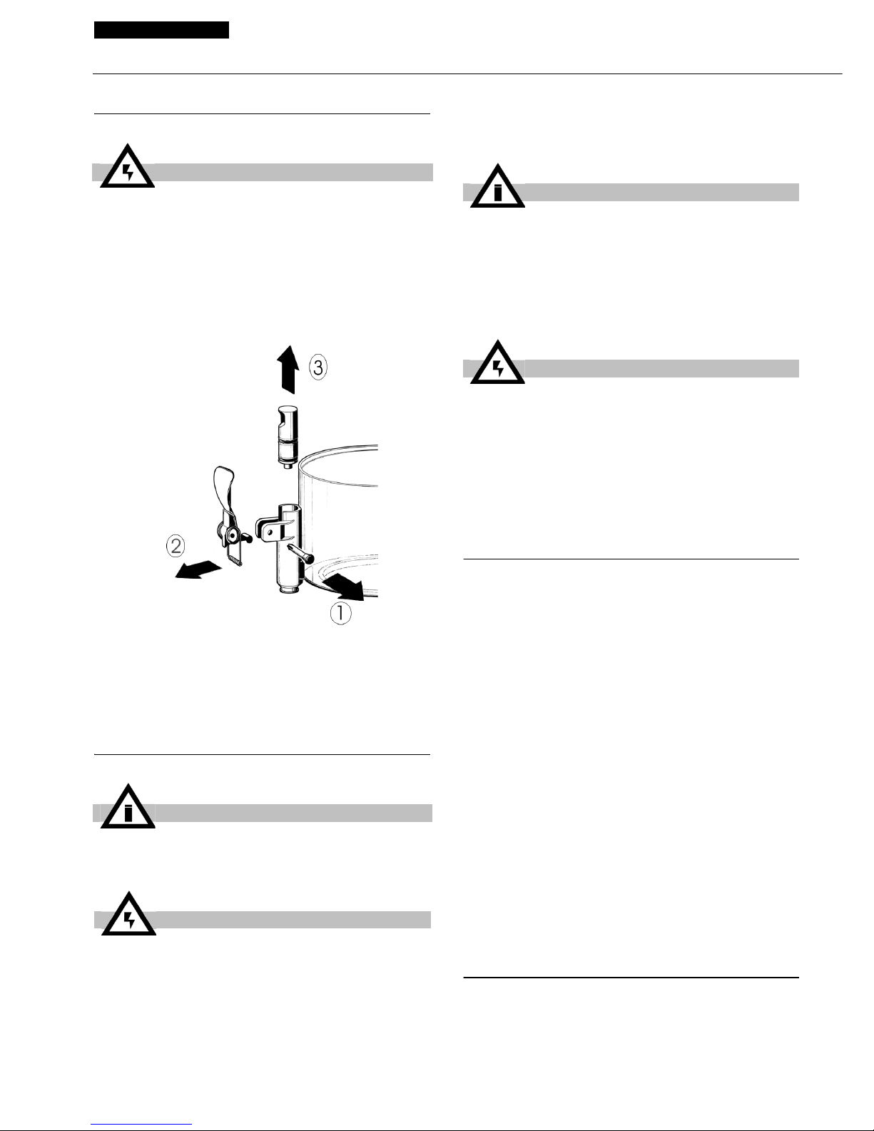
3 Dismantle the faucet following the sequence
shown (see fig. 1)
figure 1
4 Remove the container, lifting it upwards.
5 Remove the drip-tray and empty it.
7. 2 CLEANING
1 Prepare approx. four litres (2 gallons) of hot
water (45-60° C) and specific detergent in a bowl
according to the instructions of the manufacturer;
a solution, which is too concentrated, may cause
damage to the parts to be washed, one that is
too diluted will not clean adequately. Do not use
abrasive detergents.
2 Use a suitable brush and carefully clean all
the parts in contact with the drink
3 Rinse all the washed parts in running water.
7. 3 SANITIZING
The dispenser must be sanitized prior to starting
the machine, every day. Do not allow the unit to
sit for extended periods of the time after
sanitization
1 Before starting the procedure described
below wash hands with an anti-bacterial soap.
2 Prepare at least. four litres of hot water (45-
60°C) and sterilising product legally approved in
your Country, following the instructions of the
manufacturer. If there is no specific sterilising
product prepare a solution of water and bleach in
the following ratio: 1 tbsp: 2 litres of water.
3 Immerse all the parts to be sterilised in the
solution for time indicated by the manufacturer.
4 Allow the sterilised parts to air dry on a clean
surface.
5 Use non-abrasive cloths to dry the external
parts.
7. 4 ASSEMBLY
1 Put the drip-tray and grill in place
2 Lubricate the faucet piston (in the area A
shown in fig. 2) using food grade approved
ATTENTION
Before proceeding to disassemble any component always disconnect the unit from the
electricity removing the plug.
IMPORTANT
Before cleaning disconnect the dispenser
from the electricity taking out the plug.
ATTENTION
Do not wash any component of the
machine in the dishwasher.
IMPORTANT
Use detergents compatible with the plastic
parts to avoid damaging the dispenser.
ATTENTION
Do not use excessive amounts of water
near the electric components of the dispenser when washing it as this can cause
electric shock or damage the dispenser.
Page 13
13
lubricant.
figure 2
3 Reassemble the faucet assembly on the
container in the opposite way to which it was
dismantled (see fig. 1).
4 Install the container putting the central shaft
in place.
5 Insert the mixer in the central shaft
6 Position the cover on the container.
8 MAINTENANCE
1 Daily: check the dispenser for any loss of
product from the gaskets. If there is, first check
the dispenser is assembled correctly making
sure that the gaskets need no lubricating and
they are not faulty or worn. In this case they must
be replaced with original parts.
2 To avoid damage to the dispenser the plastic
parts must be lubricated only with the grease
supplied by the manufacturer or other grease
compatible with polycarbonate.
Page 14
SCIROCCO
14
ENGLISH
TROUBLESHOOTING
PROBLEM CAUSE SOLUTION
Mixer doesn't turn Drive shaft coupling not cor-
rect
Check that it's in the correct operating position
Drive shaft coupling broken Replace mixer and/or drive
shaft
Gear motor not working See “Gear motor doesn't
turn”
Electrical wires disconnected
or interrupted
Connect or replace
electrical wires
Product too dense Dilute the product
Gear motor doesn't turn Motor overheated: “Thermal
Protection” tripped
Check the voltage of the
outlet. Check the
ventilation (fins on the side
panels obstructed or lower
part of the distributor
obstructed). Check the
viscosity of the product
Stator winding burned out or
interrupted
Replace the motor
Rotor shifted Check the alignment of the
rotor bearings
Gears in the reducer box
damaged or worn
Replace the motor
Beverage leaks from the
container
Container gasket seal broken
or worn
Replace gasket seal
Tap piston o-ring broken or
worn
Replace the piston o-ring
Tap piston not in closed position
Check the tap lever or
spring and replace the
worn part
Page 15
15
Heating element not hot Heating element burned out Replace the heating
element
Thermal fuse burned out Adjust it to a suitable
temperature
Thermal fuse burned out Thermal fuse defective Replace with a good one
I'm not getting a sufficiently dense product
The temperature of the
service thermostat (located on
the side of the distributor) is
set too low
Adjust it to a suitable
temperature
Product excessively diluted Increase the concentration
of the product
I'm not getting a sufficiently hot product
The temperature of the
service thermostat (located on
the side of the distributor) is
set too low
Adjust it to a suitable
temperature
The bottom of the tub is not
touching the heating element
Position the tub on the
heating element correctly
PROBLEM CAUSE SOLUTION
Page 16
FRANCAIS
SCIROCCO
16
1 CARACTERISTIQUES
TECHNIQUES
Nous nous réservons le droit d'apporter des
modifications sans avertissement préalable.
2 INTRODUCTION
Il est nécéssaire de lire attentivement ce carnet
d’istructions, de façon à connaître toutes les
caractéristiques du distributeur.
Comme tous les produits mécaniques, ce
distributeur nécessite hygiène et soin. Son bon
fonctionnement peut être compromis par
d'éventuelles erreurs de l'opérateur au cours des
phases de montage et de nettoyage. C'est la
raison pour laquelle il est important que les
procédures quotidiennes de démontage et
remontage soient connues par tout le personnel
qui s’occupe du distributeur sans courir le risque
de commettre des erreurs.
3 INSTALLATION
1 Retirez le distributeur de l'emballage. Nous
vous conseillons de conserver l'emballage, vous
pourriez en avoir besoin plus tard.
2 Assurez-vous que le distributeur n'a pas subi
de dommages au cours du transport. Si c'est le
cas, présentez immédiatement une réclamation
auprès du transporteur.
3 Posez le distributeur sur un comptoir qui
supporte son poids lorsqu'il est plein.
4 Avant d'effectuer les branchements
électriques, vérifiez que la tension du réseau est
la même que celle indiquée sur la plaquette.
Branchez le distributeur à un réseau monophasé
à l'aide d'une prise comprenant la mise à la terre,
conformément aux normes en vigueur. En cas
d’utilisation d’un interrupteur unipolaire pour
couper l’alimentation électrique de l’appareil,
celui-ci doit garantir le respect d’une distance
d’ouverture des contacts permettant un
débranchement intégral dans des conditions de
surtension de catégorie III. N'utilisez pas de
rallonge pour brancher l'appareil au réseau
électrique.
5 Le distributeur n'est ni lavé ni désinfecté
avant de sortir de la fabrique. Avant de l'utiliser, il
vous faut le démonter, le laver et le désinfecter
suivant les indications du chapitre 7
NETTOYAGE.
4 POUR UN FONCTIONNEMENT
CORRECT ET SANS DANGER
1 N'utilisez pas le distributeur avant d'avoir lu
ce carnet d’istructions.
Scirocco
Réservoirs transparents démontables n 1
Capacité chaque réservoir, environ l 5
Dimensions:
largeur cm 24
profondeur cm 32
hauteur cm 49
Poids net, environ kg 6
Poids brut, environ kg 7
Thermostats réglables n 1
Niveau de bruit inférieur à 70 dB (A)
IMPORTANT
Caractéristiques électriques : lire les données qui figurent sur la plaquette de chaque distributeur. Cette plaquette se trouve
sous le distributeur. Les numéros d'immatriculation des appareils sont précédés du
symbole #. Les données figurant sur la plaquette sont toujours celles auxquelles vous
devez faire référence.
ATTENTION
Vérifiez que l'appareil est correctement
relié à la terre. S'il ne l'est pas, les personnes pourraient subir des chocs électriques
et le distributeur pourrait être endommagé.
IMPORTANT
Cet appareil peut être utilisé par des
enfants âgés de 8 ans ou plus et par des
personnes avec des capacités physiques,
sensorielles ou mentales réduites ou sans
expérience et connaissance seulement s'ils
sont surveillés ou ils ont reçu toute
instruction concernant l'emploi de l'appareil de façon sûre et qu'ils ont compris les
risques inhérents. Les enfants ne doivent
pas jouer avec l'appareil. Les opérations de
nettoyage et d'entretien ne doivent pas être
effectuées par les enfants sans surveillance.
Page 17
17
2 N'utilisez pas le distributeur s'il n'est pas
correctement relié à la terre.
3 N'utilisez pas de rallonge pour le
branchement électrique du distributeur.
4 Ne mettez pas le distributeur en fonction si
les panneaux ne sont pas en place et fixés par
des vis.
5 N'introduisez pas les doigts ou des objets
dans les fentes des panneaux ou dans
l'ouverture du robinet.
6 Ne retirez pas le conteneur lorsque la
machine est en route.
7 L'appareil n'est pas indiqué pour l'installation
à l'extérieur.
8 N'installez pas l'appareil en zones sujets à
jets d'eau.
9 Ne pas employer des jets d'eau pour le
nettoyage de l'appareil.
10 La température ambiante adapte pour le bon
fonctionnement de l'appareil est entre +5° et
+35°C.
5 MODE D'EMPLOI
1 Avant d'utiliser le distributeur, lavez-le et
désinfectez-le suivant les indications du chapitre
7 NETTOYAGE.
2 Remplissez le conteneur du produit voulu
préparé selon les indications du producteur.
3 Montez le couvercle sur le conteneur en
veillant à le positionner correctement.
4 Agissez sur les commandes (voir chapitre
5.1 DESCRIPTION DES COMMANDES).
5 Le distributeur doit toujours fonctionner à
couvercle fermé, afin d'éviter une éventuelle
contamination du produit.
6 Le distributeur doit fonctionner sans
interruption. Le chauffage s'arrêtera
automatiquement lorsque le produit sera prêt à la
distribution. Le dispositif d'agitation continuera à
fonctionner.
7 Le distributeur est équipé d'un conteneur à
fond clos amovible afin de faciliter les opérations
de nettoyage et désinfection.
5. 1 DESCRIPTION DES COMMANDES
Le distributeur est doté d'un interrupteur général
dont les fonctions sont :
Le distributeur est équipé d'un thermostat, placé
sur le côté droit, pour le réglage de la température
du produit.
6 SUGGESTIONS
Préparation du chocolat chaud : conformezvous à la production artisanale. Diluez bien le
cacao dans une casserole avant de le verser
dans le conteneur du distributeur. Si vous utilisez
des produits instantanés emballés, suivez les
indications du fabricant. Avec ce genre de
produits le mélange peut être effectué
directement dans le conteneur.
Actionnez ensuite le distributeur en plaçant
l'interrupteur en position I. Dans la version
normale tournez le bouton du thermostat jusqu'à
la position 90°C de façon à obtenir la température
de cuisson du produit. Lorsque le chocolat est
prêt, baissez la température à la valeur désirée
pour la distribution en tournant le bouton du
thermostat.
ATTENTION
Ne retirez par le conteneur tant que la plaque chauffante est chaude.
ATTENTION
Ne retirez pas le conteneur du distributeur
lorsque celui-ci contient du produit chaud.
IMPORTANT
L’appareil doit être installé sur une surface
horizontale.
ATTENTION
Si le câble est endommagé, il doit être remplacé par le fabricant ou par son service
technique ou de toute façon par du personnel qualifié pour éviter tout risque.
Position 0 : le distributeur est éteint.
Position I : l'agitateur et le ventilateur sont
en fonction.
IMPORTANT
Avant d'éteindre complètement le distributeur (interrupteur en position 0), placez le
thermostat sur la température minimum et
attendez que le produit refroidisse. Cela
évite que le produit, s'il n'est pas agité, ne
se colle à la plaque chauffante.
Page 18
FRANCAIS
SCIROCCO
18
7 NETTOYAGE
Laver et nettoyer le distributeur sont des
opérations fondamentales pour une parfaite
conservation du goût de la boisson et la meilleure
efficacité de votre distributeur. Les procédures
décrites ci-après doivent être considérées
comme des opérations de caractère général et
peuvent varier selon les normes sanitaires en
vigueur.
Videz le produit avant de démonter le distributeur
pour le nettoyer.
7. 1 DEMONTAGE
1 Videz le conteneur et retirez le couvercle.
2 Faites glisser le mélangeur de l'arbre central.
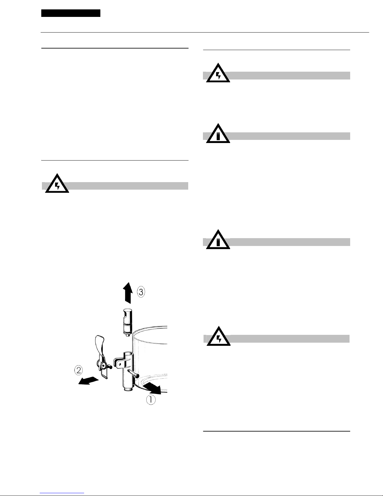
3 Démontez le robinet selon la séquence
indiquée (voir figure 1).
figure 1
4
Retirez le conteneur en le soulevant vers le
haut.
5 Faites glisser vers l'extérieur le tiroir qui
recueille les gouttes et videz-le.
7. 2 LAVAGE
1 Dans une bassine, préparez environ quatre
litres d'eau chaude (45-60°C) et du produit lavant
spécial en vous conformant aux prescriptions du
fabricant. Une solution trop concentrée peut
endommager les pièces à laver et une solution
trop diluée peut ne pas nettoyer correctement.
N'utilisez pas de produits abrasifs.
2 Utilisez une brosse adaptée et lavez
soigneusement à l'aide de la solution nettoyante
toutes les pièces qui sont en contact avec la
boisson.
3 Rincez toutes les pièces lavées à l'eau
courante.
7. 3 DESINFECTION
La désinfection doit être effectuée avant de
mettre en marche le distributeur, quotidien. Evitez
que celui-ci reste trop longtemps inactif après
avoir été désinfecté.
ATTENTION
Avant de procéder à toute intervention de
démontage, débranchez toujours le distributeur en sortant la fiche de la prise
électrique.
ATTENTION
Avant de procéder à toute intervention de
nettoyage, débranchez toujours le distributeur en sortant la fiche de la prise
électrique.
IMPORTANT
Ne lavez aucun des éléments de l'appareil
au lave-vaisselle.
IMPORTANT
Pour ne pas endommager le distributeur,
utilisez uniquement des produits lavant
adaptés aux pièces en plastique.
ATTENTION
Durant le lavage du distributeur, veillez à
ne pas utiliser trop d'eau à proximité des
composants électriques : vous pourriez
provoquer des chocs électriques ou
endommager le distributeur.
Page 19
19
1 Avant de commencer les procédures
décrites ci-après, lavez-vous les mains avec du
savon antibactérien.
2 Dans une bassine, préparez environ quatre
litres d'eau chaude (45-60°C) et de produit
désinfectant approuvé par les autorités de votre
pays en respectant les doses indiquées par le
fabricant. En l'absence de produit désinfectant
spécifique, préparez une solution d'eau et
d'hypochlorite de sodium (eau de javel) dans les
proportions suivantes : 1 cuiller pour deux litres
d'eau.
3 Immergez toutes les pièces à désinfecter
dans la solution pendant la durée indiquée par le
fabricant.
4 Laissez sécher les pièces désinfectées à
l'air, sur une surface propre.
5 Séchez les parties extérieures du
distributeur sans utiliser de linges abrasifs.
7. 4 REMONTAGE
1 Mettez le tiroir qui recueille les gouttes et la
grille en place.
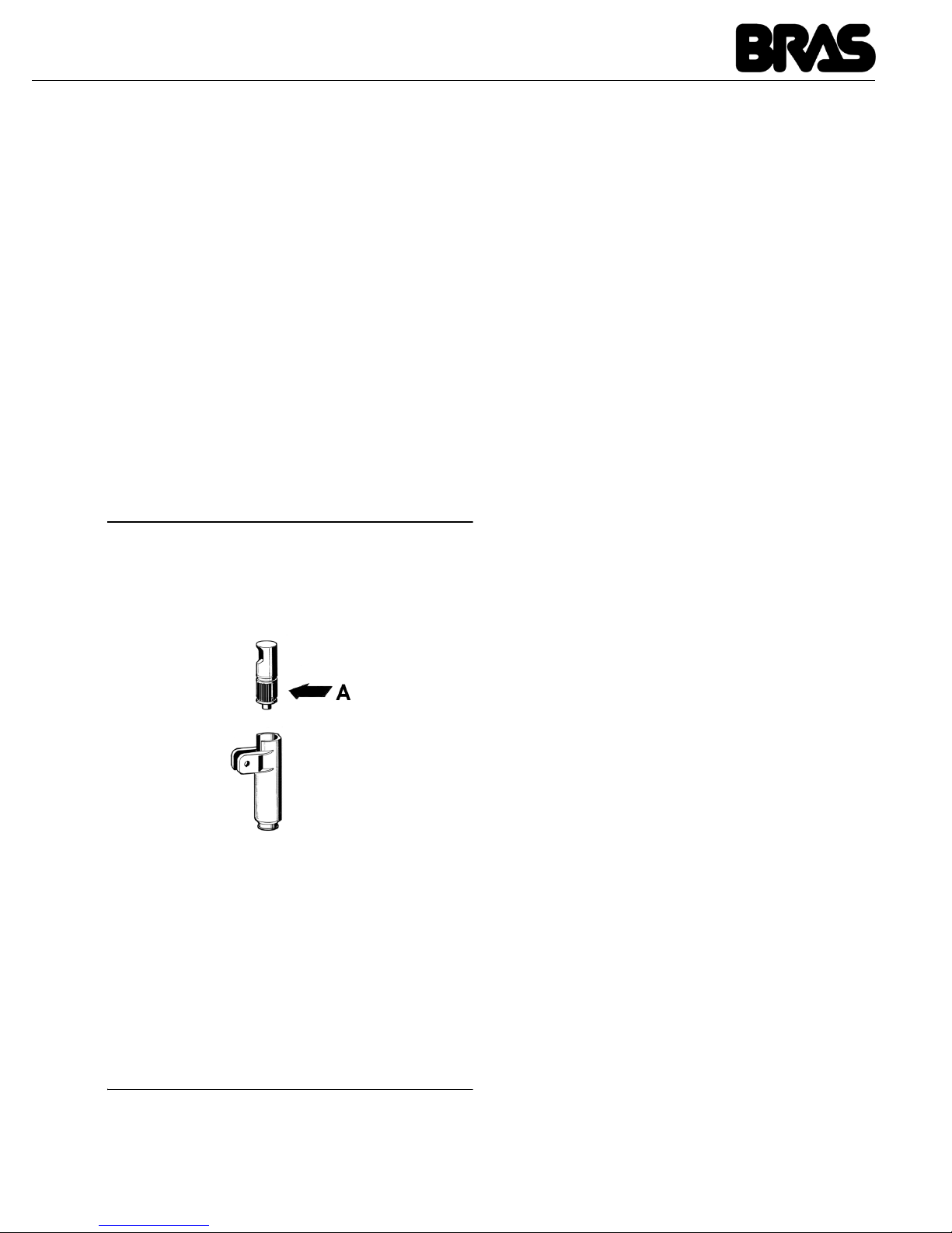
2 Lubrifiez le piston robinet (dans la zone A
indiquée sur la figure 2) uniquement avec la
graisse à usage alimentaire.
figure 2
3
Ré assemblez le robinet sur le conteneur,
dans le sens inverse des indications de
démontage (voir figure 1).
4 Montez le conteneur en enfilant l'arbre
central à sa place.
5 Insérez le mélangeur dans l'arbre central.
6 Mettez en place le couvercle sur le
conteneur.
8 ENTRETIEN
1 Quotidien : vérifiez le distributeur et vérifiez
qu'il n'y a pas de fuite de produit par les joints. Si
vous remarquez des fuites, contrôlez avant tout
le montage du distributeur. Assurez-vous ensuite
que les joints n'ont pas besoin d'être lubrifiés et
enfin qu'aucune pièce n'est défectueuse ou
abîmée. Dans ce cas, remplacez-la avec une
pièce de rechange originale du fabricant.
2 Pour éviter d'endommager le distributeur,
lubrifiez les pièces en plastique uniquement avec
de la graisse fournie par le fabricant ou une autre
graisse compatible avec le polycarbonate.
Page 20
SCIROCCO
20
FRANCAIS
INCONVENIENTS EVENTUELS ET SOLUTIONS
PROBLEME CAUSE SOLUTION
Le mélangeur ne tourne
pas
Le branchement sur l'arbre de
transmission n'est pas
effectué correctement
Vérifier la bonne position
de fonctionnement
Le branchement sur l'arbre de
transmission est cassé
Remplacer le mélangeur
et/ou l'arbre de transmission
Le motoréducteur ne fonctionne pas
Voir “le motoréducteur ne
tourne pas”
Les conducteurs électriques
sont débranchés ou interrompus
Relier ou remplacer les
conducteurs électriques
La densité du produit est
excessive
Diluer davantage le produit
Le motoréducteur ne
tourne pas
Le moteur est surchauffé :
intervention du “protecteur
thermique”
Contrôler le voltage de la
prise de courant. Contrôler
la ventilation (ailettes des
panneaux latéraux
obstruées ou partie
inférieure du distributeur
obstruée). Contrôler la
viscosité du produit
La bobine de l'inducteur est
brûlée ou interrompue
Remplacer le moteur
Le rotor est désaxé Contrôler l’alignement des
coussinets du rotor
Les engrenages de la boîte
du réducteur sont endommagés ou usés
Remplacer le moteur
La boisson fuit du conteneur
Le joint du conteneur est
détérioré ou usé
Remplacer le joint
L'O-Ring du piston robinet est
détérioré ou usé
Remplacer l'O-Ring du piston
Le piston robinet n'est pas
fermé
Contrôler le levier ou le
ressort du robinet et remplacer la partie usée
Page 21
21
La résistance ne chauffe
pas
La résistance est brûlée Remplacer la résistance
Le thermolimitateur de
sécurité est brûlé
Voir “le thermolimitateur
de sécurité est brûlé”
Le thermolimitateur de
sécurité est brûlé
Le thermolimitateur est
défectueux
Le remplacer par un neuf
Je n'arrive pas à obtenir
un produit suffisamment
dense
Le thermostat de service
(placé sur le côté du
distributeur) est réglé sur une
température trop basse
Le régler à la bonne
température
Le produit est trop dilué Augmenter la
concentration du produit
Je n'arrive pas à obtenir
un produit suffisamment
chaud
Le thermostat de service
(placé sur le côté du
distributeur) est réglé sur une
température trop basse
Le régler à la bonne
température
Il n'y a pas ce contact entre le
fond du réservoir et la
résistance
Placer correctement le
réservoir sur la résistance
PROBLEME CAUSE SOLUTION
Page 22
SCIROCCO
22
DEUTSCH
1 TECHNISCHE DATEN
Wir behalten uns das Recht vor, ohne
Vorankündigung Änderungen vorzunehmen.
2 EINFÜHRUNG
Es ist nötif Ihnen, das vorliegende
Anleitungshandbuch aufmerksam zu lesen, um
sich mit allen Eigenschaften des Distributors
vertraut zu machen.
Wie alle mechanischen Bauteile macht auch
dieser Distributor eine sorgfältige Reinigung und
Pflege erforderlich. Der ordnungsgemäße Betrieb
kann außerdem durch eventuelle Fehler des
Bedieners während der Zerlegung und der
Reinigung beeinträchtigt werden. Aus diesem
Grund ist es wichtig, dass die täglichen
Prozeduren Zerlegung, Reinigung,
Hygienisierung und Montage bekannt sind, so
dass Fehler durch das für den Distributor
personal ausgeschlossen werden können.
3 INSTALLATION
1 Der Distributor aus seiner Verpackung
entnehmen, die für zukünftige Verwendungen
aufbewahrt werden muss.
2 Sicherstellen, dass der Distributor während
des Transports keinerlei Beschädigung erfahren
hat. Anderenfalls dem Spediteur sofort Meldung
erstatten.
3 Den Distributor auf einen Tisch auflegen, der
in der Lage ist, das Gewicht auch mit voller
Füllung zu tragen.
4 Vor dem elektrischen Anschließen des
Distributors sicherstellen, dass die
Netzspannung mit der auf dem Typenschild
angegebenen Betriebsspannung übereinstimmt.
Den Distributor unter Verwendung eines
Netzsteckers mit Erdung unter Beachtung der
geltenden Bestimmungen an das
Einphasenstromnetz anschließen. Sollte das
Trennen des Geräts von der Stromversorgung
über einen allpoligen Schalter erfolgen, muss
dieser Schalter einen Öffnungsabstand der
Kontakte garantieren, der die vollständige
Unterbrechung zu den Bedingungen der
Überspannungskategorie III gestattet. Für den
elektrischen Anschluss des Gerätes keine
Verlängerungskabel verwenden.
5 Der Distributor verlässt das Werk nicht
vorgereinigt und hygienisiert. Vor der Benutzung
muss es daher zerlegt, gereinigt und hygienisiert
werden; dabei die Anweisungen im
entsprechenden Abschnitt 7 REINIGUNG
beachten.
4 SICHERHEITSMAßNAHMEN
1 Den Distributor nicht benutzen, bevor das
vorliegenden Anweisungshandbuch gelesen
worden ist.
2 Den Distributor nicht benutzen, wenn es
nicht ordnungsgemäß geerdet worden ist.
3 Für den elektrischen Anschluss des
Distributors keine Verlängerungskabel benutzen.
Scirocco
Abnehmbare Klarsicht-Behälter stück 1
Fassungsvermögen Einzelbehälter,
ungefähr
l 5
Abmessungen:
Breite cm 24
Tiefe cm 32
Höhe cm 49
Nettogewicht, ca kg 6
Bruttogewicht, ca kg 7
Einstellbare Thermostaten stück 1
Geräuschpegel unter 70 db (A)
WICHTIG
Elektrische Eigenschaften: Die auf dem
Typenschild eines jeden einzelnen Distributors angegebenen Daten lesen; das Typenschild befindet sich unter dem Distributor.
Den Seriennummer der Geräte geht das
Symbol # voraus. Es muss stets auf die
Daten Bezug genommen werden, die auf
dem Typenschild angegeben werden.
ACHTUNG
Sicherstellen, dass das Gerät ordnungsgemäß geerdet worden ist; anderenfalls
besteht die Gefahr von elektrischen
Schlägen für Personen sowie die Gefahr
der Beschädigung des Distributors.
Page 23
23
4 Den Distributor nicht in Betrieb nehmen,
wenn er nicht geschlossen und mit Schrauben
gesichert ist.
5 Nicht die Finger oder Gegenstände in die
Kühlungsschlitze oder die Öffnung des Hahns
einführen.
6 Den Behälter nicht entfernen, wenn die
Maschine in Betrieb ist
7 Dieses Geräte wurde nicht für den Betrieb im
Freien entwickelt.
8 Dieses Gerät darf nicht in Bereichen
aufgestellt werden, in denen Wassertropfen
seien können.
9 Nicht mit einem Dampfstrahler reinigen.
10 Dieses Gerät kann bei Raumtemperaturen
zwischen +5° und +35°C betrieben werden.
5 GEBRAUCHSANLEITUNGEN
1 Den Distributor vor der Benutzung unter
Beachtung der Anweisungen in Abschnitt 7
REINIGUNG des vorliegenden Handbuches
spülen und hygienisieren.
2 Den Behälter mit dem gewünschten Produkt
füllen, das unter Beachtung der Anweisungen
des Herstellers zuzubereiten ist.
3 Die Abdeckung über dem Behälter
anbringen und sicherstellen, dass sie
ordnungsgemäß positioniert worden ist.
4 Die Bedienelemente betätigen(siehe
Abschnitt 5.1 BESCHREIBUNG DER
BEDIENELEMENTE).
5 Der Distributor muss immer mit montierter
Abdeckung in Betrieb genommen werden, um
eine eventuelle Verunreinigung des Produkts zu
vermeiden.
6 Der Distributor muss ununterbrochen
betrieben werden: Die Heizung schaltet sich
automatisch ab, wenn das Produkt für die
Ausgabe fertig ist. Das Rührwerk läuft weiter.
7 Der Distributor weist einen Behälter mit
geschlossenem Boden auf, der zur
Vereinfachung der Reinigung und
Hygienisierung entfernt werden kann.
5. 1 BESCHREIBUNG DER
BETRIEBSSCHALTER
Der Distributor weist einen Hauptschalter mit den
folgenden Funktionen auf:
Der Distributor weist auf der rechten Seite
außerdem ein Thermostat für die Einstellung der
Temperatur des Produkts auf.
6 NÜTZLICHE HINWEISE
WÄHREND DES GEBRAUCHS
Zubereitung von Schokolade: Unter Beachtung
der Handwerklichen Vorgehensweise den Kakao
ACHTUNG
Den Behälter nicht entfernen, bis die
Heizplatte kalt ist.
ACHTUNG
Den Behälter nicht vom Distributor entfernen, wenn dieser heißes Produkt enthält.
WICHTIG
Das Geräte muss auf einer waagerechten
Oberfläsche ausgestellt werden.
ACHTUNG
Sollte dieser beschädigt sein, muß das
Stromkabel ausgetauscht werden, umder
Gefahr eines Stromschlages vorzubeugen.
Dieser Austausch darf nur vonqualifizierten Fachleuten ausgeführt werden.
WICHTIG
Dieses Gerät ist nicht für den Gebrauch von
Personen, insbesondere Kindern, mit eingeschränkten physischen oder mentalen
Fähigkeiten bestimmt. Ausserdem sollte
das Gerät nicht mit einem Mangel an
Erfahrung oder Verständnis bedient werden, bevor nicht eine Einweisung von
einem Fachmann erfolgt ist.
Es ist sicherzustellen, dass Kinder nicht
unbeaufsichtigt in die Nähe der Maschine
gelangen.
Position 0 : der Distributor ist abgeschaltet
Position I : sowohl das Rührwerk, als auch
die Heizung sind in Betrieb.
Page 24
SCIROCCO
24
DEUTSCH
in einer Kasserolle temperieren, bevor er in den
Behälter des Distributors gegossen wird. Bei
Verwendung von konfektionierten InstantProdukte die Anweisungen des Herstellers
beachten. Bei diesem Produkttyp kann die
Mischung direkt im Behälter vorgenommen
werden.
Den Distributor einschalten, indem der Schalter in
Position I gebracht wird. In der normalen Version
den Knauf des Thermostats in die Position 90 °C
drehen, so dass die Temperatur für das Kochen
des Produkts erreicht wird. Wenn die Schokolade
fertig ist, die Temperatur durch Drehen des
Thermostatknaufs auf den für die Ausgabe
gewünschten Wert senken.
7 REINIGUNG
Zur Gewährleistung einer perfekten
Konservierung des Geschmacks des Getränkes
sowie der uneingeschränkten Effizienz Ihres
Distributors sind das Spülen und die Reinigung
von grundlegender Bedeutung. Die im Folgenden
beschriebenen Prozeduren haben allgemeinen
Charakter und unterliegen in Abhängigkeit von
den geltenden Hygienebestimmungen
Abweichungen.
Vor dem Zerlegen des Distributors für das Spülen
muss das Produkt entleert werden.
7. 1 DEMONTAGE
1 Den Behälter entleeren und die Abdeckung
abnehmen.
2 Das Rührwerk von der zentralen Welle
abziehen.
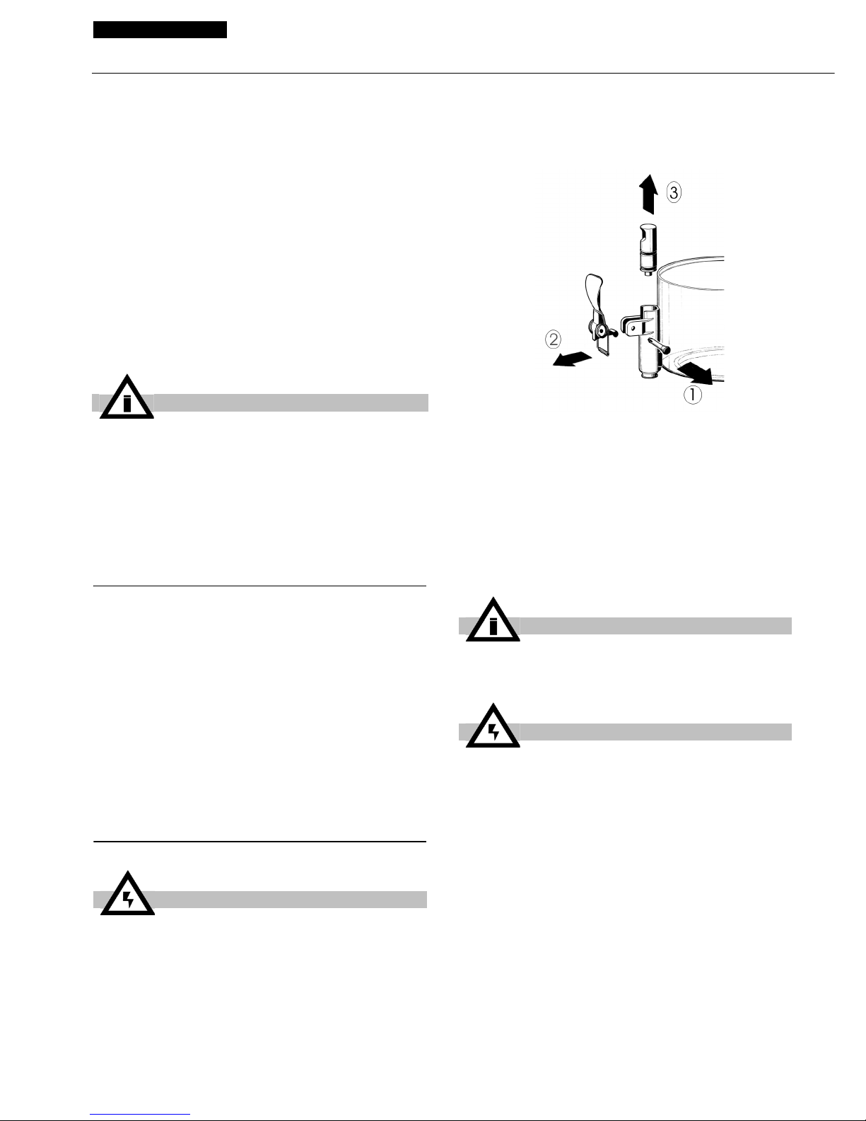
3 Den Hahn in der angegebenen Reihenfolge
zerlegen (siehe Abbildung 1).
Bild 1
4
Den Behälter entnehmen, indem er nach
oben abgehoben wird.
5 Die Tropfschublade herausnehmen und
ausleeren.
6 WASCHENEin Becken mit ca. vier Litern
heißem Wasser und spezifischem
Reinigungsmittel vorbereiten und dabei die
Angaben des Herstellers genau einhalten; eine
zu starke Konzentration kann eine Beschädigung
der zu reinigenden Bauteile verursachen,
während eine zu starke Verdünnung die
Reinigungswirkung beeinträchtigt. Keine
scheuernden Reinigungsmittel verwenden.
7 Eine geeignete Bürste benutzen und alle
Bauteile, die mit dem Getränk in Kontakt
kommen, sorgfältig mit der Reinigungslösung
WICHTIG
Vor dem vollständigen Abschalten des
Distributors (Schalter in Position 0) das
Thermostat auf die Position der Mindesttemperatur einstellen und warten, bis das
Produkt abgekühlt ist. Dadurch wird vermieden, dass das (nicht umgerührte) Produkt
auf der Heizplatte festklebt.
ACHTUNG
Vor dem Abbauen von Komponenten die
Stromversorgung des Gerätes unterbrechen; dazu den Netzstecker aus der Netzsteckdose ziehen oder den Wandschalter
öffnen.
WICHTIG
Die Komponenten der Maschine nicht in
der Spülmaschine reinigen.
ACHTUNG
Vor allen Reinigungsarbeiten die elektrische Speisung des Distributors unterbrechen; dazu den Netzstecker aus der
Netzsteckdose ziehen oder den Wandschalter öffnen.
Page 25
25
reinigen.
8 Alle gereinigten Bauteile unter fließendem
Wasser abspülen.
7. 2 DESINFEKTION
Die Hygienisierung muss unmittelbar vor der
Inbetriebnahme des Distributors
vorgenommen werden, täglich; eine längere
Nichtbenutzung nach der Hygienisierung
muss vermieden werden.
1 Vor Beginn der im Folgenden beschriebenen
Prozeduren die Hände mit antibakterieller Seife
waschen.
2 Eine Wanne mit ca. vier Litern Lösung aus
heißem Wasser (45 - 60 °C) und
Hygienisierungsprodukt zubereiten, das von den
Behörden Ihres Landes genehmigt worden ist;
dabei die Angaben des Herstellers beachten.
Falls kein spezifisches Hygienisierungsmittel
vorhanden ist, eine Lösung aus Wasser und
Natriumhypochlorit (Chlorbleichlauge) in einem
Verhältnis von 1 Löffel je 2 Liter Wasser
zubereiten.
3 Alle zu hygienisierenden Bauteile für die vom
Hersteller des Produkts angegebene Zeit in die
Lösung eintauchen.
4 Die hygienisierten Bauteile auf einer
sauberen Fläche an der Luft trocknen lassen.
5 Die Außenflächen des Distributors
abtrocknen; dabei keine kratzenden Lappen
verwenden.
7. 3 MONTAGE
1 Die Tropfschublade und den Rost in seinen
Sitz einsetzen.
2 Den Kolben des Hahns (in Bereich A,
gezeigt auf Abbildung 2) ausschließlich mit
einem lebenmitteltauglichen Fett schmieren.
Bild 2
3
Den Hahn an den Behälter anbauen; dabei
mit Bezug auf die Zerlegung in der umgekehrten
Reihenfolge vorgehen (siehe Abbildung 1).
4 Den Behälter montieren und dabei die
zentrale Welle in den entsprechenden Sitz
einführen.
5 Den Mischer auf die zentrale Welle
einführen.
6 Die Abdeckung auf dem Behälter
positionieren.
8 WARTUNG
1 Täglich: Den Distributor kontrollieren und
überprüfen, ob an den Dichtungen Produkt
austritt. Im Falle von Lecks zuerst kontrollieren,
ob der Distributor ordnungsgemäß montiert ist,
dann kontrollieren, ob die Dichtungen geschmiert
werden müssen, und anschließend kontrollieren,
ob die Dichtungen beschädigt oder abgenutzt
sind; in diesem Fall müssen sie durch
Originalersatzteile des Herstellers ersetzt
werden.
2 Zur Vermeidung von Beschädigungen des
Distributors dürfen die Kunststoffbauteile
ausschließlich mit dem vom Hersteller
gelieferten Fett oder einem anderen mit
Polykarbonat kompatiblem Fett geschmiert
werden.
ACHTUNG
Während der Reinigung des Distributors
keine zu große Menge Wasser in der Nähe
der elektrischen Komponenten verwenden;
anderenfalls besteht die Gefahr von elektrischen Schlägen oder die Gefahr einer
Beschädigung des Distributors.
WICHTIG
Zur Vermeidung von Beschädigungen des
Distributors ausschließlich Reinigungsmittel verwenden, die mit den Bauteilen aus
Kunststoff kompatibel sind.
Page 26
SCIROCCO
26
DEUTSCH
MÖGLICHE STÖRUNGEN UND IHRE BEHEBUNG
PROBLEM URSACHE ABHILFE
Mischvorrichtung dreht
sich nicht
Verbindung an Mitnahmewelle nicht richtig erfolgt
Die richtige Betriebsposition prüfen
Verbindung zu Mitnahmewelle
defekt
Mischvorrichtung und /
oder Mitnahmewelle
austauschen
Getriebe nicht funktionsfähig Siehe unter "Das Getriebe
dreht sich nicht"
Elektrische Leiter gelöst oder
unterbrochen
Die elektrischen Leiter
anschließen oder
austauschen
Zu hohe Dickflüssigkeit des
Produktes
Das Produkt stärker verdünnen
Getriebe dreht sich nicht Motor überhitzt: “Thermo-
schutz” ausgelöst
Die Spannung des
Stromanschlusses prüfen.
Die Belüftung prüfen
(Lamellen der
Seitenwände oder unterer
Teil des Verteilers
verschlossen). Die
Viskosität des Produktes
prüfen
Statorwicklung durchgebrannt oder defekt
Den Motor austauschen
Rotor nicht gelagert Die Ausrichtung der Motor-
lager prüfen
Zahnräder im Getriebe
beschädigt oder abgenutzt
Den Motor austauschen
Austritt von Getränk aus
dem Behälter
Dichtung des Gehäuses
defekt oder abgenutzt
Die Dichtung austauschen
O-Ring des Ventilkolbens
defekt oder abgenutzt
Die O-Ringe des Kolbens
austauschen
Ventilkolben nicht in geschlossener Position
Den Hebel oder die Feder
des Ventils prüfen und den
abgenutzten Teil austauschen
Page 27
27
Der Widerstand erwärmt
sich nicht
Widerstand durchgebrannt Den Widerstand
austauschen
SicherheitsTemperaturbegrenzer
durchgebrannt
Siehe unter “SicherheitsTemperaturbegrenzer
durchgebrannt”
Sicherheits-Temperaturbegrenzer durchgebrannt
Temperaturbegrenzer defekt Durch einen
funktionstüchtigen
ersetzen
Es gelingt nicht, ein ausreichend dickflüssiges
Produkt zu erzielen.
Das Betriebsthermostat
(seitlich des Verteilers) ist auf
eine zu niedrige Temperatur
eingestellt
Auf die entsprechende
Temperatur einstellen
Produkt zu stark verdünnt Die Konzentration des
Produktes erhöhen
Es gelingt nicht, ein ausreichend heißes Produkt zu erzielen.
Das Betriebsthermostat
(seitlich des Verteilers) ist auf
eine zu niedrige Temperatur
eingestellt
Auf die entsprechende
Temperatur einstellen
Es besteht kein Kontakt
zwischen Beckenboden und
Widerstand
Das Becken richtig auf
dem Widerstand
positionieren
PROBLEM URSACHE ABHILFE
Page 28

SCIROCCO
28
ESPAÑOL
1 CARACTERÍSTICAS TÉCNICAS
Se reserva el derecho de aportar modificaciones
sin previo aviso.
2 INTRODUCCIÓN
Es necesario leer atentamente este manual de
instrucciones a fin de conocer todas las
características del distribuidor.
Al igual que todos los productos mecánicos, este
distribuidor necesita ciertos cuidados y limpieza.
Su buen funcionamiento podría depender
además de posibles errores cometidos por el
operario en las fases de desmontaje y de
limpieza. Por este motivo es importante que las
operaciones de desmontaje, lavado,
saneamiento y montaje, siendo éstas diarias, se
conozcan bien sin posibilidad de error a quien va
a utilizar el distribuidor.
3 INSTALACIÓN
1 Extraer el distribuidor del embalaje; se
aconseja su conservación en caso de futura
necesidad.
2 Comprobar que el distribuidor no haya
sufrido daños en el transporte. En caso
contrario, proceder inmediatamente a hacer las
reclamaciones pertinentes al transportista.
3 Apoyar el distribuidor sobre una mesa para
descansar el peso, incluso a carga completa.
4 Antes de proceder a la instalación eléctrica
del distribuidor, comprobar que la tensión de la
red sea la indicada en la placa. Conectar el
distribuidor en una red monofase, ayudándose
de una toma a tierra en conformidad con las
normas vigentes. Si la desconexión del aparato
de la red eléctrica se realiza mediante un
interruptor omnipolar, este debe garantizar una
distancia de apertura de los contactos que
permita la desconexión completa, en las
condiciones previstas para la categoría de
sobretensión III. No utilizar alargos para realizar
la conexión eléctrica del aparato.
5 El distribuidor no viene lavado y saneado de
fábrica. Antes de usarlo, es necesario
desmontarlo, lavarlo y sanearlo siguiendo las
instrucciones del capítulo 7 LIMPIEZA.
Scirocco
Contenedores transparentes desmontables
n 1
Capacidad de cada contenedor,
aproximada
l 5
Dimensiones:
ancho cm 24
largo cm 32
alto cm 49
Peso neto, aproximado kg 6
Peso bruto, aproximado kg 7
Termostatos regulables n 1
Nivel de ruido inferior a 70dB (A)
IMPORTANTE
Características eléctricas: leer los datos
indicados en la placa de cada distribuidor;
ésta se encuentra bajo el mismo distribuidor. Los números de matrícula de los aparatos están precedidos por el símbolo #.
Los datos indicados en la placa son los
únicos datos de referencia.
ATTENCION
Comprobar que el aparato esté conectado
a tierra correctamente; en caso contrario
se corre el peligro de electrocución de las
personas o de causar daños en el distribuidor.
Page 29
29
4 PARA UN FUNCIONAMIENTO
SEGURO Y CORRECTO
1 No usar el distribuidor antes de haber leído
el presente manual de instrucciones.
2 No usar el distribuidor si la conexión a tierra
no es correcta.
3 No usar alargos para la conexión eléctrica
del distribuidor.
4 No poner en funcionamiento el distribuidor si
no está cerrado y debidamente fijado con
tornillos.
5 No introducir los dedos ni objetos en las
fisuras de refrigeración y en la apertura del grifo.
6 No extraer el contenedor cuando la máquina
está en funcionamiento.
7 Aparato no apto para uso exterior.
8 Aparato no apto en instalaciones donde
haya cercano fuentes de agua .
9 Para la limpieza no utilizar chorros de agua.
10 Para el correcto funcionamiento, coma la
temperatura ambiente debe estar comprendida
ientre 5°C y 35°C.
5 INSTRUCCIONES DE EMPLEO
1 Lavar y sanear el distribuidor antes de
utilizarlo siguiendo las instrucciones del capítulo
7 LIMPIEZA.
2 Llenar el contenedor con el producto
deseado, preparado según las instrucciones del
fabricante.
3 Montar la tapa encima del contenedor
comprobando que quede colocada
correctamente.
4 Utilizar los mandos (véase el capítulo 5.1
DESCRIPCIÓN DE LOS MANDOS).
5 El distribuidor debe funcionar siempre con la
tapa montada para evitar que el producto se
contamine.
6 El distribuidor debe funcionar
ininterrumpidamente: el calentamiento se parará
automáticamente cuando el producto esté listo
para la distribución. El dispositivo de agitación
seguirá funcionando.
7 El distribuidor dispone de contenedor con
fondo cerrado extraíble para facilitar las
operaciones de limpieza y saneamiento.
5. 1 DESCRIPCIÓN DE LOS
MANDOS
El distribuidor dispone de un interruptor general
cuyas funciones son:
IMPORTANTE
Este aparato puede ser usado por niños
mayores de 8 años o por personas con su
capacidad física, psíquica o sensorial reducida o por quienes no tengan los conocimientos y la experiencia necesarios sólo
cuando sean supervisados o instruidos
acerca del uso del aparato y de los riesgos
posibles por una persona responsable de
su seguridad. Vigilen que los niños no jueguen con los equipos. Vigilen que las operaciones de limpieza y mantenimiento no
sean efectuadas por niños no supervisados.
ATTENCION
No extraer el contenedor hasta que la placa
calefactora esté fría.
ATTENCION
No extraer el contenedor del distribuidor si
éste contiene producto caliente.
IMPORTANTE
El aparato debe ser instalado sobre un
plano horizontal.
ATTENCION
Si el cable de alimentación está dañado,
debe ser substituito por el fabricante o
desde su servicio de asistencia técnica o,
en cualquier caso, por una persona cualificada con el fin de evitar cualquier tipo de
riesgo.
Posición 0 : el distribuidor está apagado
Posición I : funcionan tanto el dispositivo
de agitación como el dispositivo
de calentamiento.
Page 30
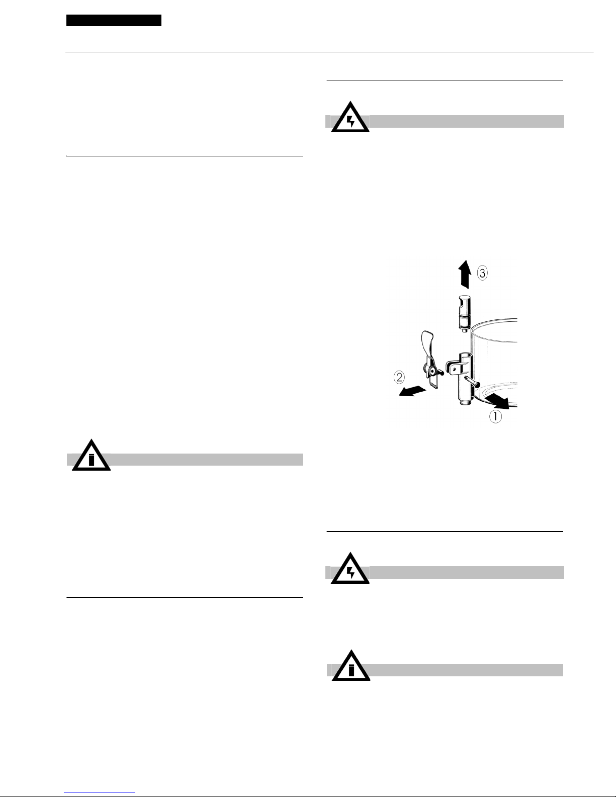
SCIROCCO
30
ESPAÑOL
El distribuidor también dispone de un termostato
situado en el lado derecho para regular la
temperatura del producto.
6 SUGERENCIAS
Preparación del chocolate: siguiendo el método
artesanal, disolver bien el cacao en una cazuela
antes de verterlo en el contenedor del
distribuidor. En caso de utilizar productos
instantáneos envasados, seguir las instrucciones
del fabricante. Con este tipo de productos, la
mezcla puede efectuarse directamente en el
contenedor.
A continuación, accionar el distribuidor colocando
el interruptor en posición I. Girar el mando del
termostato hasta la posición de 90°C para
obtener la temperatura de cocción del producto.
Cuando el chocolate esté listo, bajar la
temperatura al valor deseado para la distribución
mediante el mando del termostato.
7 LIMPIEZA
Limpieza y lavado son fundamentales para
garantizar la perfecta conservación del gusto de
la bebida y la máxima eficacia del distribuidor.
Los procedimientos descritos a continuación
deben considerarse de carácter general y
pueden variar por efecto de la reglamentación
sanitaria vigente.
Antes de desmontar el distribuidor para su
lavado, es necesario vaciar el producto.
7. 1 DESMONTAJE
1 Vaciar el contenedor y quitar la tapa.
2 Extraer el mezclador del eje central.
3 Desmontar el grifo siguiendo la secuencia
indicada (véase figura 1).
figura 1
4
Levantar el contenedor para extraerlo.
5 Extraer el cajón recogegotas y vaciarlo.
7. 2 LAVADO
1 Llenar un barreño con aproximadamente
cuatro litros de agua caliente (45-60°C) y
IMPORTANTE
Antes de apagar por completo el distribuidor (posición 0), poner el termostato a la
posición de temperatura mínima y esperar
a que el producto se enfríe. Así se evitará
que el producto (si no se agita) se pegue a
la placa calefactora.
ATTENCION
Antes de desmontar cualquier componente
desconectar siempre el aparato de la corriente extrayendo la clavija de la toma de
corriente.
ATTENCION
Antes de proceder a las operaciones de limpieza, desconectar siempre el aparato de la
corriente extrayendo la clavija de la toma de
corriente.
IMPORTANTE
No lavar ningún componente de la máquina
en el lavavajillas.
Page 31
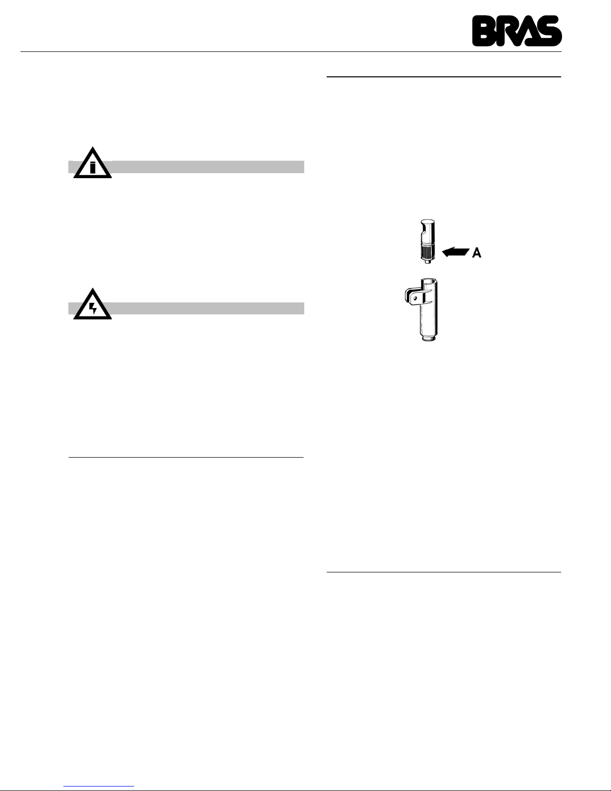
31
detergente específico respetando rigurosamente
las instrucciones del fabricante; una solución
demasiado concentrada puede causar daños en
las partes a lavar, mientras que una solución
demasiado diluida puede no limpiar lo suficiente.
No usar detergentes abrasivos.
2 Usar un cepillo adecuado y lavar con
cuidado con la solución detergente todas las
piezas en contacto con la bebida.
3 Enjuagar con agua corriente todas las piezas
lavadas.
7. 3 HIGIENIZACION
El saneamiento debe efectuarse junto antes de
poner en funcionamiento el distribuidor, todos los
días; evitar que éste permanezca inactivo
durante mucho tiempo después del saneamiento.
1 Antes de iniciar los procedimientos descritos
a continuación, lavarse las manos con un jabón
antibacterias
2 Llenar un barreño con aproximadamente
cuatro litros de solución de agua caliente (4560°C) y producto saneador aprobado por las
autoridades del país de utilización en
conformidad con las especificaciones del
fabricante. Si no se dispone de un producto
saneador específico, preparar una solución de
agua e hipoclorito de sodio (lejía) a razón de 1
cuchara por cada 2 litros de agua.
3 Sumergir en la solución todas las piezas que
deban sanearse durante el tiempo indicado por
el fabricante del producto.
4 Dejar secar al aire, sobre una superficie
limpia, las piezas saneadas.
5 Secar las piezas externas del distribuidor sin
utilizar trapos abrasivos.
7. 4 REMONTAJE
1 Montar el cajón recogegotas y la rejilla en
sus alojamientos correspondientes.
2 Lubricar el pistón del grifo (en la zona A
indicada en la Figura 2) utilizando
exclusivamente la grasa adecuada para uso
alimentario.
figura 2
3
Volver a montar el grifo en el contenedor
siguiendo el orden inverso de las operaciones de
desmontaje (véase Figura 1).
4 Montar el contenedor colocando el eje
central en su alojamiento.
5 Montar el mezclador en el eje central.
6 Colocar la tapa en el contenedor.
8 MANUTENCION
1 Todos los días: comprobar el estado del
distribuidor y verificar que no haya pérdidas de
producto en las juntas. Si se detectan pérdidas,
controlar en primer lugar que el distribuidor esté
correctamente montado; a continuación,
comprobar que las juntas no precisen
lubricación, así como que no estén defectuosas
o desgastadas. En este caso, sustituirlas por
recambios originales del fabricante.
2 A fin de prevenir daños en el distribuidor, las
piezas de plástico deben lubricarse únicamente
con la grasa proporcionada por el fabricante o
con otra grasa compatible con policarbonato.
IMPORTANTE
A fin de prevenir daños en el distribuidor,
utilizar solamente detergentes compatibles
con las piezas de plástico.
ATTENCION
Durante el lavado del distribuidor, no utilizar excesiva cantidad de agua cerca de los
componentes eléctricos; en caso contrario
se podría correr el riesgo de electrocución
o de daños en el distribuidor.
Page 32
SCIROCCO
32
ESPAÑOL
POSIBLES PROBLEMAS Y CÓMO SOLUCIONARLOS
PROBLEMA CAUSA SOLUCIÓN
La mezcladora no gira La introducción en el eje de
remolque no se ha efectuado
correctamente
Comprobar que la posición
de funcionamiento sea
correcta
Introducción en eje de remolque roto
Sustituir la mezcladora y/o
el eje de remolque
El motorreductor no funciona Véase "El motorreductor
no gira"
Los conductores eléctricos
están desconectados o interrumpidos
Conectar o sustituir los
conductores eléctricos
La densidad del producto es
excesiva
Diluir más el producto
El motorreductor no gira El motor está sobrecalen-
tado: intervención del “Protector térmico”
Comprobar el voltaje de la
toma de corriente.
Comprobar la ventilación
(aletas de los paneles
laterales o parte inferior del
distribuidor obstruidas).
Comprobar la viscosidad
del producto
El arrollado del estator se ha
quemado o se ha interrumpido
Sustituir el motor
El rotor está desalineado Comprobar la alineación
de los cojinetes del rotor
Los engranajes de la caja del
reductor están dañados o
desgastados
Sustituir el motor
Hay pérdidas de bebida
en el contenedor
La junta del contenedor está
rota o desgastada
Sustituir la junta
El anillo O-Ring del pistón de
la llave está roto o
desgastado
Sustituir los O-Ring del pistón
El pistón de la llave no está en
posición de cierre
Comprobar la palanca o el
resorte de la llave y sustituir la pieza desgastada
Page 33
33
La resistencia no calienta La resistencia está quemada Sustituir la resistencia
El limitador de temperatura de
seguridad está quemado
Véase "limitador de
temperatura de seguridad
quemado"
El limitador de temperatura de seguridad está
quemado
El limitador de temperatura
está defectuoso
Sustituirlo por otro que se
encuentre en perfecto
estado
No consigo obtener un
producto suficientemente denso
El termostato de servicio
(situado al lado del
distribuidor) está regulado a
una temperatura demasiado
baja
Regularlo a la temperatura
adecuada
El producto está demasiado
diluido
Aumentar la concentración
del producto
No consigo obtener un
producto suficientemente caliente
El termostato de servicio
(situado al lado del
distribuidor) está regulado a
una temperatura demasiado
baja
Regularlo a la temperatura
adecuada
El fondo de la cuba y la
resistencia no se tocan
Colocar la cuba encima de
la resistencia de manera
correcta
PROBLEMA CAUSA SOLUCIÓN
Page 34
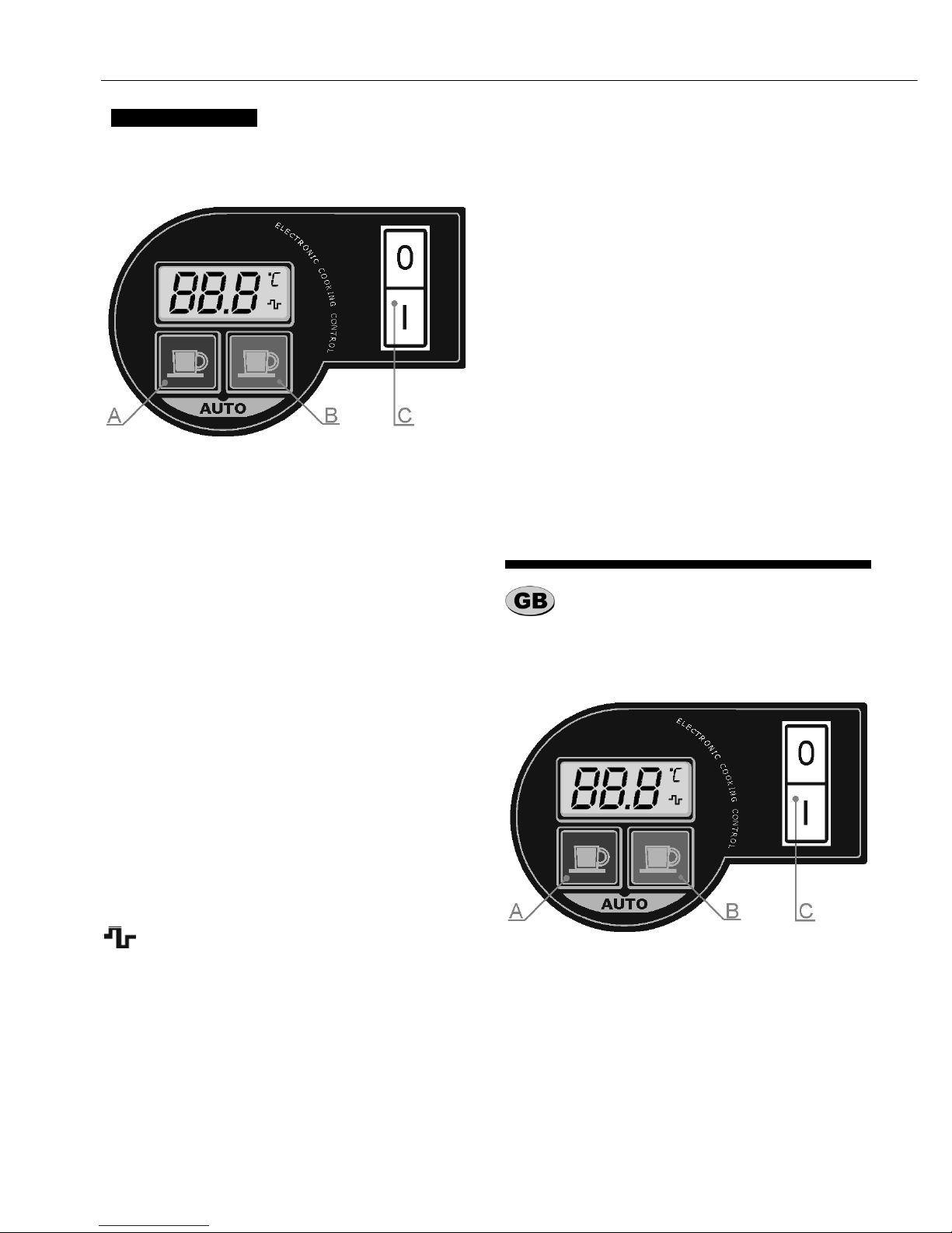
SCIROCCO
34
Il distributore è provvisto di un interruttore generale C le cui funzioni sono le seguenti:
Il distributore è inoltre dotato di un sistema elettronico di regolazione della temperatura del prodotto.
Tale sistema è dotato di due tasti le cui funzioni
sono le seguenti:
Il sistema è infine dotato di un display sul quale
vengono visualizzati la temperatura desiderata
per il prodotto, l’indicazione della scala utilizzata
per la visualizzazione della temperatura, gradi
centigradi (°C) o Fahrenheit (°F) ed il simbolo
che indica l’accensione dell’elemento riscaldante.
All’accensione vengono avviati tanto il riscaldamento quanto il dispositivo di agitazione e sul display viene mostrata la temperatura desiderata
per il prodotto. Tale visualizzazione sarà lampeggiante fintantoché il prodotto non avrà raggiunto
la temperatura impostata.
Allo spegnimento l’impostazione della temperatu-
ra desiderata viene memorizzata e mantenuta
per la successiva accensione.
CICLO DI COTTURA AUTOMATICA
Il distributore è in grado di eseguire un ciclo di cottura automatica. Tale ciclo comporta il riscaldamento del prodotto ad una temperatura di 95 °C
ed il suo mantenimento a tale temperatura per 15
minuti. Al termine del ciclo di cottura il prodotto
viene riportato alla temperatura impostata inizialmente, prima cioè dell’avvio del ciclo di cottura.
E’ possibile avviare il ciclo di cottura automatica
del prodotto premendo contemporaneamente i
due tasti A e B.
La temperatura e la durata del ciclo di cottura automatica sono impostati dalla fabbrica rispettivamente a 95 °C e 15 minuti. Essi possono tuttavia
essere modificati. Per fare ciò è sufficiente spegnere il distributore agendo sull’interruttore generale C e riaccenderlo tenendo premuto il tasto A.
Sul display verrà mostrato il tempo di cottura,
espresso in minuti, che potrà essere diminuito o
aumentato utilizzando i tasti A e B e confermato
premendo contemporaneamente i due tasti. Verrà quindi mostrata la temperatura di cottura che
potrà, anch’essa, essere diminuita o aumentata
utilizzando i tasti A e B e confermata premendo
contemporaneamente i due tasti.
The dispenser is equipped with a general switch
whose functions are:
The dispenser is also equipped with an electronic
device, located on the right side, to control the
temperature of the product. This device has one
VERSIONE ELETTRONICA (OPZIONALE)
Posizione 0 : il distributore è spento.
Posizione I : funzionano sia il dispositivo di
agitazione che il riscaldamento.
Tasto A : permette di diminuire la temperatura
un grado alla volta; tenendolo premuto per più di due secondi sarà invece possibile diminuire
velocemente la temperatura.
Tasto B : permette di aumentare la temperatu-
ra un grado alla volta; tenendolo premuto per più di due secondi sarà
invece possibile aumentare velocemente la temperatura.
ITALIANO
ELECTRONIC VERSION (OPTIONAL)
Position 0 : power is turned off.
Position I : mixing and hating on.
Page 35
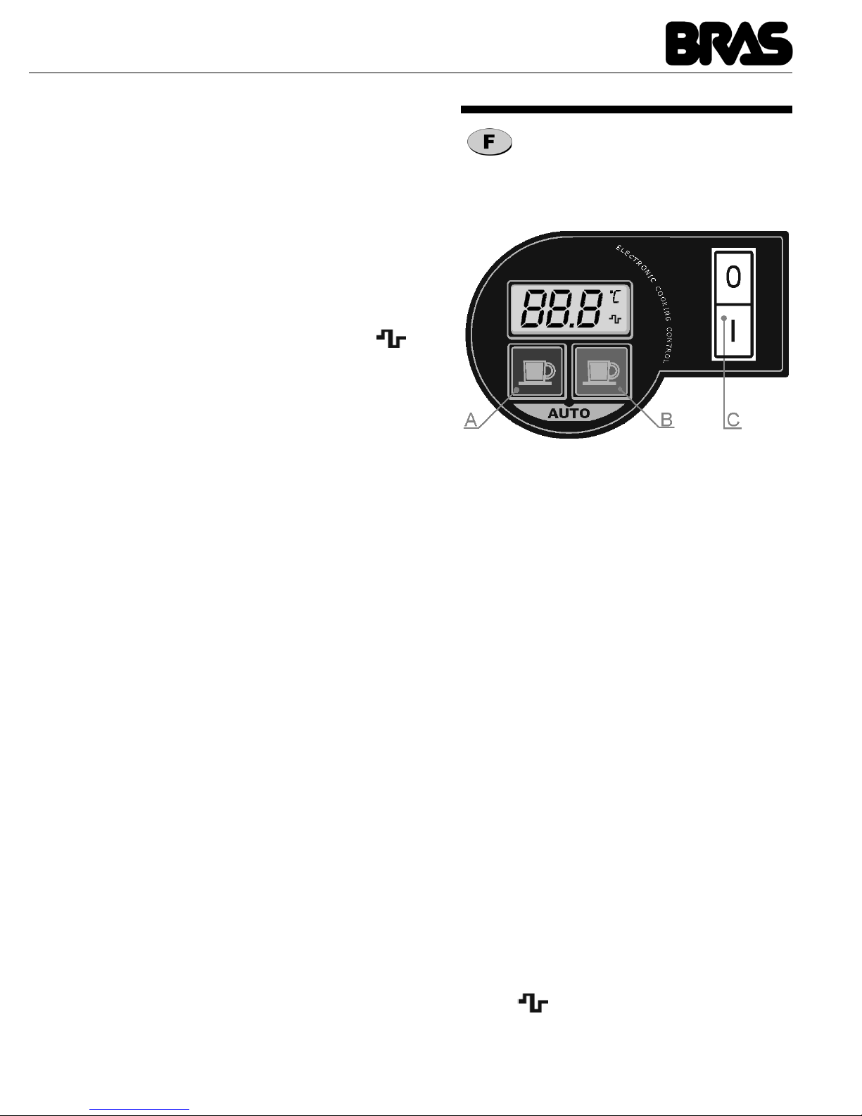
35
display, to show the set temperature and two keys
whose functions are the following:
On the display, the symbols °C or °F indicates the
current temperature unit and the symbol indicates the turning on of the heating element.
When the dispenser is turned on, both the mixing
and the heating are turned on and on the display
the set temperature is shown. The set temperature value blinks until when the product has reached the desired temperature.
When the dispenser is turned OFF all the current
settings are saved into memory to be effective at
the following power on.
AUTOMATING COOKING CYCLE
By pressing together key A and B the dispenser
performs an Automatic Cooking Cycle. This means that the product is heated up to 95 °C and
maintained at this temperature for 15 minutes.
After the expiration of the Automatic Cooking
Cycle the product is maintained at the desired
temperature set before the cycle.
The temperature and the length of the Automatic
Cooking Cycle are factory preset. To reset them
turn the dispenser off and then turn it on keeping
key A pressed. On the display the Cooking Temperature is shown and it is possible to decease or
increase it using keys A or B and to confirm it
pressing both keys together. Then the length of
the Cooking Cycle is shown and it is possible to
decease or increase it using keys A or B and to
confirm it pressing both keys together.
L'interrupteur C de l'appareil a les fonctions les
suivantes:
L'appareil a un système électronique qui permet
de régler la température de la boisson dans la
cuve.
Le système a deux boutons dont les fonctions
sont les suivantes :
Le système est doté d'un écran montrant la
température désirée pour le produit, l'indication
de l'échelle utilisée pour la visualisation de la
température, graduée en °C ou °F et le
symbole qui indique l'allumage de l'élément
réchauffant.
Key A : to decrease the desired temperature
one degree by one; by keeping it
pressed for more than two seconds it
is possible to quickly decrease the
temperature.
Key B : to increase the desired temperature
one degree by one; by keeping it
pressed for more than two seconds it
is possible to quickly increase the
temperature.
VERSION ELECTRONIQUE (OPTION)
Position 0 : l'appareil est éteint.
Position I : mélangeur et chauffage sont en
fonction
Bouton A : chaque poussée permet de
baisser la température d'1
degré. En restant appuyé plus
de 2 secondes, le degré de
température pourra être baissé
plus rapidement.
Bouton B : chaque poussée permet d'aug-
menter la température d'1 degré.
En restant appuyé plus de 2 secondes, le degré de température
pourra être augmenté plus rapidement.
Page 36
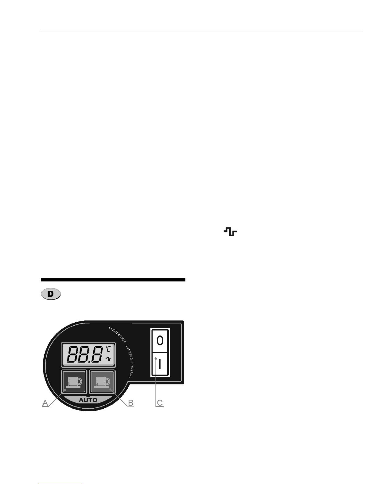
SCIROCCO
36
A la mise en marche de l'appareil, le mélangeur
et le chauffage sont mis en route et l'écran montre
la température fixée. L'indication de température
clignote jusqu'à ce que celle-ci soit atteinte. Lorsque l'on éteint l'appareil, la température est
mémorisée pour l'utilisation future.
CUISSON AUTOMATIQUE
L'appareil peut effectuer un cycle de cuisson automatique.
Pour mettre en marche le cycle de cuisson automatique, appuyer simultanément sur les boutons
A et B : le produit est alors chauffé jusqu'à 95°C
et cette température est maintenue pendant 15
minutes. Une fois le cycle de cuisson automatique terminé, le produit est maintenu à la température mémorisée.
Les paramètres de température et de durée du
cycle de cuisson automatique (réglé par défaut à
95°C et 15 min.) peuvent être changés.
Pour cela, éteindre l'appareil à l'aide de l'interrup-
teur C et rallumer le en appuyant en même temps
sur le bouton A. Sur l'écran apparaît le temps de
cuisson, exprimé en minutes ; il s'augmente ou se
baisse à l'aide des boutons A et B et s'enregistre
en appuyant sur ces 2 boutons simultanément.
Puis le temps de cuisson du cycle de cuisson automatique apparaît ; comme pour la température,
il se règle à l'aide des boutons A et B et s'enregistre en appuyant sur ces 2 boutons simultanément.
Der Dispenser ist auf dem Bedienfeld mit einem
Hauptschalter C ausgerüstet, dessen Funktion
wie folgt sind:
Des weiteren ist der Dispenser auf der rechten
Seite mit einer elektronischen Steuerung
ausgestattet, welche die Temperatur des
Produkts überwacht. Das Bedienerfeld ist mit
einem Display ausgestattet, welches die
eingestellte Temperatur anzeigt und zwei
Bedienelementen, deren Funktion wie
nachfolgend beschrieben ist:
Im Display zeigen die Symbole °C oder °F die
aktuelle Temperatur des Gerätes und das
Symbol zeigt an, dass das Heizelemente in
Betrieb ist.
Wenn der Dispenser eingeschaltet wird, so wird
sowohl das Rührwerk als auch die Heizspirale
eingeschaltet und auf dem Display wird die
voreingestellte Temperatur angezeigt. Die
Anzeige blinkt dabei solange, bis das Produkt die
gewünschte Temperatur erreicht hat.
Wenn der Dispenser ausgeschaltet wird, so werden alle aktuellen Einstellung bis zur nächsten Inbetriebnahme gespeichert.
AUTOMATISCHER ERHITZUNGSPROZESS
Indem Sie die Tasten A und B auf dem Bedienerfeld zusammen betätigen, führt der Dispenser einen automatischen Erhitzungsprozess durch.
Dies bedeutet, dass das Produkt auf 95 °C erhitzt
und bei dieser Temperatur für 15 Minuten gehalten wird. Danach wird das Produkt auf der voreingestellten Temperatur gehalten. Die Temperatur
und die Länge des automatischen Erhitzungsprozesses sind werkseitig eingestellt. Um diese zu
ändern, schalten Sie den Dispenser aus und halten Sie, während Sie den Dispenser wieder einschalten, die Taste A auf dem Bedienerfeld
gedrückt. In dem Display wird nun die werkseitig
eingestellte Temperatur angezeigt, welche Sie
durch Betätigen der Taste A oder B entsprechend einstellen und durch Drücken beider Ta-
ELEKTRONISCHE VERSION (OPTIONAL)
Position 0 : Das Gerät ist ausgeschaltet.
Position I : Das Gerät ist betriebsbereit.
Taste A : Durch Drücken wird die
gewünschte Temperatur um 1°C
abgesenkt. Hält man die Taste
länger als 2 Sekunden gedrückt
ist es möglich, die Temperatur
schneller abzusenken.
Taste B : Durch Drücken wird die
gewünschte Temperatur um 1°C
erhöht. Hält man die Taste
länger als 2 Sekunden gedrückt,
ist es möglich die Temperatur
schneller anzuheben.
Page 37
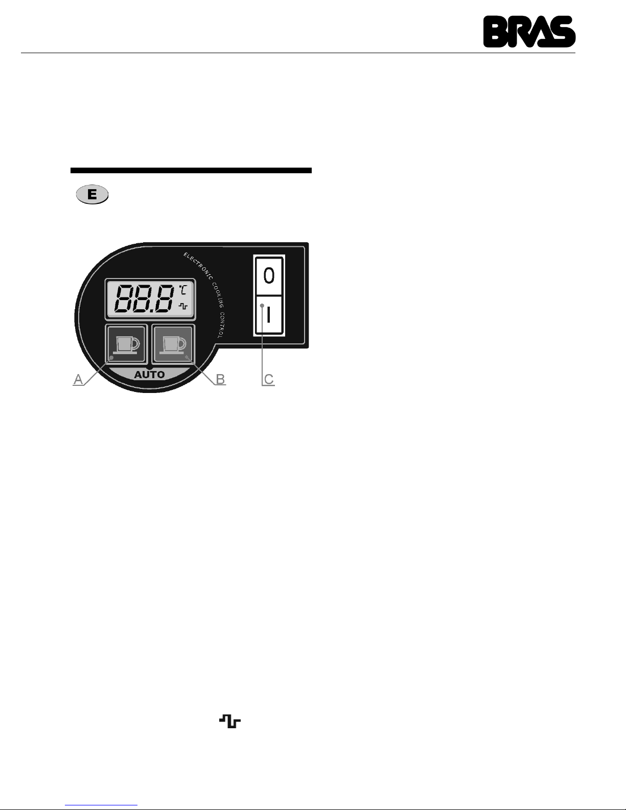
37
sten speichern. Gleichzeitiges Drücken der
Tasten speichert den veränderten Wert. Anschließend wird die Kochzeit angezeigt, welche
Sie durch Betätigen der Tasten A oder B einstellen und durch Drücken beider Tasten speichern.
El distribuidor està provisto de un interruptor
general C cuyas funciones son :
El distribuidor està ademàs dotado de un sistema
de regulaciòn de la temperatura del producto.
Tal sistema està dotado de dos teclas cuyas
funciones son las siguientes :
El sistema està dotado de un display en el cual
vienen visualizadas la temperatura deseada para
el producto, grados centrigrados (°C) o
Fahrenheit (°F) y el simbolo que indica el
ascenso del "elemento de calentamiento "
Con el encendido se inicia sea el calentamiento
que el dispositivo de mezcla y en el display viene
mostrada la temperatura seleccionada ( deseada
para el producto).
Dicha visualizaciòn parpadearà hasta que el
producto no haya alcanzado dicha temperatura.
Con el apagado, la selecciòn de la temperatura
deseada viene memorizada y se mantiene hasta
el encendido sucesivo.
CICLO DE COCCION AUTOMATICA
El distribuidor dispone de un ciclo de cocciòn automatica. Dicho ciclo conlleva al calentamiento
del producto a una temperatura de 95° C. y lo
mantiene a esta temperatura durante 15 minutos.
Al final del ciclo de cocciòn el producto alcanzarà
la temperatura seleccionada anteriormente, antes delinicio del ciclo de cocciòn.
Es posible iniciar el ciclo de cocciòn automàtica
del producto pulsando a la vez las teclas A y B.
La temperatura y duraciòn del ciclo de cocciòn
automàtica vienen preseleccionadas de fabrica a
95° y 15 minutosrespectivamente. Pueden ser
sempre modificadas. Para ello es sufficiente
apagar el distribuidor actuando en el interruptor
general C y reencendiendolo teniendo pulsada la
tecla A. En el display viene mostrado el tempo de
cocciòn, en minutosm, el cual podrà ser disminuido o aumentado utilizando las teclas A y B,
ademàs se confirmarà spretando a la vez las dos
teclas. Serà asi visualizada la temperatura de
cocciòn, la cual a su vez podrà ser disminuida o
aumentada utilizando las teclas A y B, y confirmada pulsando a la vez las dos teclas.
VERSIÓN ELECTRÓNICA (OPCIONAL)
Posición 0 : el distribuidor està apagado.
Posición I : funcionan sea el dispositivo de
mezcla,como el de
calentamiento.
Tecla A : permite disminuir la
temperatura grado a grado;
teniendolo pulsado durante
màs de dos segundos serà
posible disminuir ràpidamente
la temperatura.
Tecla B : permite aumentar la
temperatura grado a grado;
teniendolo pulsado durante
màs de dos segundos serà
posible aumentar rapidamente
la temperatura.
Page 38
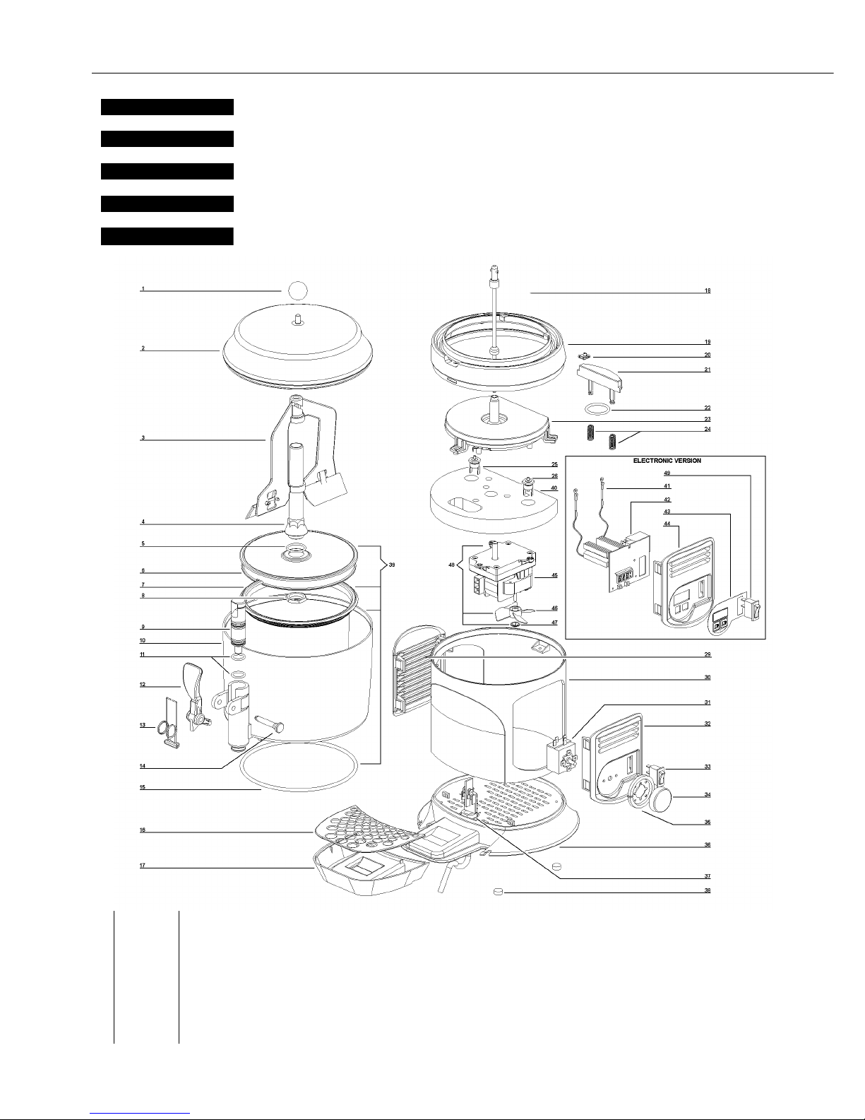
SCIROCCO
38
ELENCO RICAMBI
DA MATRICOLA 58866
A
FTER SERIAL NR. 58866
A'
PARTIR DU NR. DE SERIE 58866
N
ACH SERIEN NR. 58866
D
ESDE MATRICULA NR. 58866
SPARE PARTS LIST
LISTE DES PIECES DE RECHANGE
ERSATZTEILLISTE
DESCRIPCION PIEZAS DE REPUESTO
ITALIANO
ENGLISH
FRANCAIS
DEUTSCH
ESPAÑOL
1 22500-02000 Pomello per coperchio Cover knob Pommeau du couvercle Deckelgriff Pomo para tapa
2 22800-26409 Coperchio Bowl cover Couvercle du réservoir Deckel Tapa contenedor
2 22800-26429 Coperchio oro Golden bowl cover Couvercle du réservoir doré Goldfarbig Deckel Tapa contenedor oro
3 22800-26414 Mescolatore Mixer Mélangeur Rührwerk Mezclador
4 22800-26486 Albero contenitore plastica Plastic bowl shaft Arbre du réservoir plastic Zentralwelle kunststoff
Arbol del contenedor de plástico
4 22800-26488 Albero contenitore acciaio Steel bowl shaft Arbre du réservoir acier Zentralwelle stahl Arbol del contenedor acero
5 22500-01302 OR albero centrale Bowl shaft O-ring OR de l’arbre du réservoir O-ring für Zentralwelle OR para àrbol central
6 22800-26492 Fondo contenitore Bowl bottom plate Fond du réservoir Behältergrundplatte Fondo del contenedor
7 22800-26410 Guarnizione Bowl gasket Joint du réservoir Behälterdichtung Junta contenedor
8 10533-13005 Dado albero centrale Central shaft nut Ecru arbre du réservoir Zentralspindel Dado para eje central
9 22800-14801 Pistone per rubinetto Faucet piston Piston du robinet Kolben für Hahn Pistón del grifo
10 22800-26405 Contenitore trasparente Bowl Réservoir Behälter Contenedor
2451_99 V 5.1 16A22
Page 39

39
11 22800-15100 OR per rubinetto Faucet piston O-ring Joint OR du robinet O-ring für Piston Junta OR del grifo
12 22700-01860 Leva rubinetto verde Green faucet handle Levier de débit vert Zapfhebel Palanca grifo
12 22700-01801 Leva rubinetto nera Black Faucet handle Levier de débit noir Zapfhebel Palanca grifo
13 22800-26424 Molla rubinetto Faucet spring Ressort du robinet VentilFeder Muelle del grifo
14 22800-22161 Perno verde per leva Green faucet handle pin
Pivot vert pour levier de débit
Fixierstift (grün) Pivote verde de la palanca
14 22800-22160 Perno nero per leva Black faucet handle pin Pivot noir pour levier de débit Fixierstift (scharwz)
Pivote negro de la palanca grifo
15 22800-26418 OR per contenitore Bowl O-ring OR du réservoir O-ring für behälter OR del contenedor
16 22500-01900 Griglia cassetto Drip tray cover Couvercle tiroir égouttoir Tropfgitter Rejilla cajón recoge-gotas
17 22800-26404 Cassetto nero Black drip tray Tiroir égouttoir noir Tropfschale Cajón recoge-gotas nero
17 22800-26464 Cassetto bianco White drip tray Tiroir égouttoir blanc Tropfschale Cajón recoge-gotas blanco
17 22800-26434 Cassetto oro Drip tray gold Tiroir égouttoir or
Goldfarbig Tropfensammelschub
Bandeja goteo oro
17 22800-26439 Cassetto argento Drip tray silver Tiroir égouttoir argent Silberfarbig Tropfensam-
melschub
Bandeja goteo plata
18 33800-09801 Albero di trascinamento Driving shaft Arbre de trainement Antriebswelle Eje transmisión
19 22800-26408 Supporto piastra riscaldante Heating plate holder Support plaque chauffante Halter für Heizplatte Soporte para plancha calen-
tadora
19 22800-26427 Supporto piastra riscaldante oro Golden heating plate holde Support doré plaque chauffante Goldfarbig halter für
Heizplatte
Soporte para plancha calen-
tadora oro
20 10554-44000 Clip M4 M4 Clip Clip M4 Klip M4 Clip M4
21 22800-26491 Blocchetto portabulbo Thermostat holder Support boule du thermostat
Halter für Thermostat Kontroll
Guia-sensor termóstato
22 22500-01301
OR per fissaggio blocchetto portabulbo
O ring for # 21
OR pour support boule du thermostat O-ring für # 21 OR para guia-sensor termóstato
23 33800-09730 Piastra riscaldante 230V50Hz Heating plate Plaque chauffante Heizung- Platte Plancha calentadora
23 33800-09731 Piastra riscaldante 115V60Hz Heating plate Plaque chauffante Heizung- Platte Plancha calentadora
24 22800-26420 Molla per blocchetto portabulbo Spring for holder # 21 Ressort pour support boule Feder für Halterung # 21 Muelle para guia-sensor ter-
móstato
25 22500-01600 Termostato 5-125 °C fisso Thermostat fixed 5-125°C Thermostat fixe 5-125°C
Thermostat Festnetz 5-125°C
Termostato fijo 5-125°C
26 22800-26426 Termostato di sicurezza Limit switch Thermolimiteur Sicherung Fusible de seguridad
29 22800-26463 Pannello laterale bianco White side panel Panneau latéral blanc Seitenteil Panel lateral blanco
29 22800-26403 Pannello laterale nero Black side panel Panneau latéral noir Seitenteil Panel lateral nero
29 22800-26433 Pannello laterale oro Golden side panel Panneau latéral doré Goldfarbig seitenteil Panel lateral oro
29 22800-26438 Pannello laterale argento Side panel silver Panneau latéral argent Silberfarbig Seitenteil Panel lateral plata
30 22800-26461 Corpo macchina bianco White cabinet Carrosserie blanc Korpus Cuerpo maquina blanco
30 22800-26401 Corpo macchina nero Black cabinet Carrosserie noir Korpus Cuerpo maquina nero
30 22800-26431 Corpo macchina oro Golden cabinet Carrosserie doré Goldfarbig korpus Cuerpo maquina oro
30 22800-26436 Corpo macchina argento Silver cabinet Carrosserie -”argent” Silberfarbig Korpus Cuerpo maquina plata
31 22037-00000 Termostato 5-95°C 5-95°C thermostat Thermostat 5-95°C Thermostat 5-95°C Termóstato 5-95°C
32 22800-26462 Pannello lato comandi bianco White side panel for con-
trols
Panneau latéral pour contrôles
noir blanc
Seitenteil auf Kontrollenseite
Panel lateral lado controles
blanco
32 22800-26402 Pannello lato comandi nero Black side panel for con-
trols
Panneau latéral pour contrôles
noir
Seitenteil auf Kontrollenseite
Panel lateral lado controles
nero
32 22800-26432 Pannello lato comandi oro Golden side panel for con-
trols
Panneau latéral pour contrôles
doré
Goldfarbig seitenteil mit
Bedieneinheit
Panel lateral completo
de mandos oro
32 22800-26437 Pannello lato comandi argento Side panel for controls sil-
ver
Panneau latéral pour contrôles argent
Silberfarbig Seitenteil mit
Bedieneinheit
Panel lateral completo de
mandos plata
33 22800-24301 Interruttore Switch Interrupteur Wegeschalter Interruptor
34 22800-26458 Manopola termostato 0-90 °C Thermostat knob
Pommeau du thermostat Drehknopf für Thermostat Pomo para termostato
34 22800-26456 Manopola termostato 32-194 F Thermostat knob
Pommeau du thermostat Drehknopf für Thermostat Pomo para termostato
35 22800-26466 Ghiera Mounting Ring for # 34 Mancon Montagenzwinge for # 34 Fijador
36 22800-26460 Basamento bianco White base Base blanc Grundplatte Base blanco
36 22800-26400 Basamento nero Black base Base noir Schwarz Grundplatte Base nero
36 22800-26430 Basamento oro Golden base Base doré Goldfarbige grundplatte Base oro
36 22800-26435 Basamento argento Base silver Base argent Silberfarbige Grundplatte Base plata
37 22800-05501 Passabloccacavo Cable clamp Borne Anschlußklemme m. Kabe-
leinfürung
Pasacable
38 22800-26417 Piedino in gomma Rubber leg Petit pied Justifüße Piede de goma
39 33800-09903 Contenitore completo di fondo Bowl assembly Réservoir complet avec fond
Behälter mit Boden aus Edelstahl
Contenedor completo
40 22800-26493 Isolante resistenza Insulation resistance Résistance d'isolement Isolationswiderstand Resistencia de aislamiento
41 22800-26441 Sensore temperatura cioccola-
tiera
Hotdrink temperature sensor
Sonde de température de Hotdrink
Hotdrink Temperaturfühler Sensor de temperatura de
Hotdrink
42 22800-26448 Scheda elettronica 230V/50Hz Electronic device 230V/
50Hz
Circiut imprimé de contrôle Elektronik Circuito electronico
42 22800-26449 Scheda elettronica 115V/60Hz Electronic device 115V/
60Hz
Circiut imprimé de contrôle Elektronik Circuito electronico
43 22800-26482 Tastiera a membrana Master control clavier à la membrane Tastatur zur Membrane teclado a la membrana
44 22800-26480 Pannello lato comandi bianco White side panel for con-
trols
Panneau latéral pour contrôles
noir blanc
Seitenteil auf Kontrollenseite
Panel lateral lado controles
blanco
44 22800-26450 Pannello lato comandi nero Black side panel for con-
trols
Panneau latéral pour contrôles
noir
Seitenteil auf Kontrollenseite
Panel lateral lado controles
nero
44 22800-26452 Pannello laterale per comandi -
oro
Side panel for controls gold Panneau latéral pour contrôles orGoldfarbig Seitenteil mit
Bedieneinheit
Panel lateral completo de
mandos oro
44 22800-26453 Pannello laterale per comandi -
argento
Side panel for controls silver
Panneau latéral pour contrôles
argent
Silberfarbig Seitenteil mit
Bedieneinheit
Panel lateral completo de
mandos plata
45 Motoriduttore Complete gear motor Motoréducteur complet Getriebmotor Motorreductor completo
46 22500-02450 Ventola Fan blade Hélice Lüfterflügel Aspas
47 10520-65000 Ranella Washer Laveuse Waschmaschine Lavadora
48 Motoriduttore completo
da ser.nr.69407 - completo di staffa fissaggio motore - non compatibile con
mod.anteriori ser.nr. 58865
Complete gear motor
from ser.nr.69407 - complete with
motor bracket / not compatible with
units prior to ser.nr. 58865
Motoréducteur complet
A' partie de la ser. nr.69407 - complet
avec support du moteur - non compable
avec mod. anterieurs à ser.nr. 58865
Getriebmotor
nach ser.nr.69407 - komplett mit
Motorhalterbuegel - nicht kompatibel mit mod. zu ser.nr. 58865
Motorreductor completo
por ser.nr.69407 - completo con
placa soporte motor - no es compati-
ble con mod. anterior à ser.nr. 58865
49 22800-24300 Interruttore Switch Interrupteur Wegeschalter Interruptor
230V 50Hz 240V 50Hz 115V 60Hz 220V 60HZ
45 22092-00012 22092-00015 22092-00014 22092-00012
48 22500-02410 22500-02411 22500-02412 22500-02411
Page 40
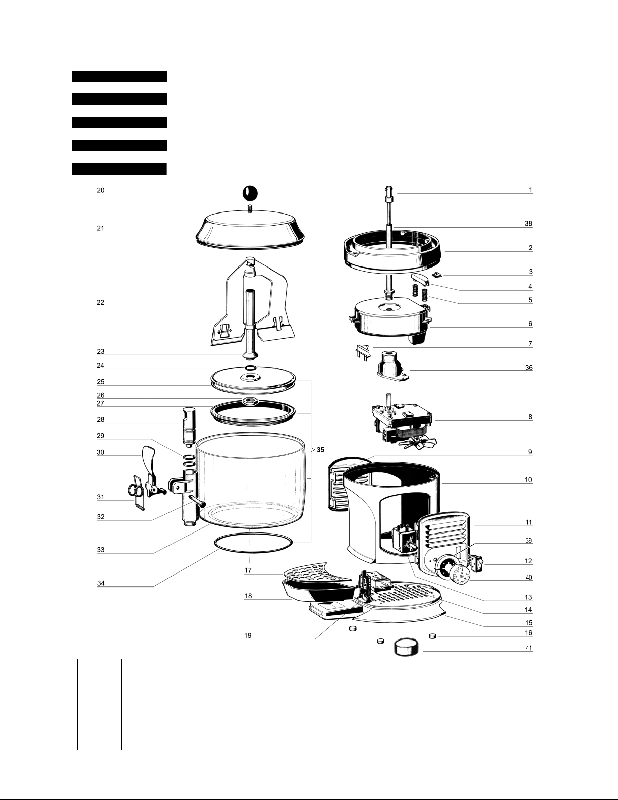
SCIROCCO
40
ELENCO RICAMBI
FINO A MATRICOLA NR. 58865
T
ILL SERIAL NR. 58865
J
USQU'AU NR. DE SERIE 58865
B
IS SERIEN NR. 58865
H
ASTA MATRICULA NR. 58865
SPARE PARTS LIST
LISTE DES PIECES DE RECHANGE
ERSATZTEILLISTE
DESCRIPCION PIEZAS DE REPUESTO
ITALIANO
ENGLISH
FRANCAIS
DEUTSCH
ESPAÑOL
1 33800-09800 Albero di trascinamento Driving shaft Arbre de trainement Antriebswelle Eje transmisión
2 22800-26408 Supporto piastra riscaldante Heating plate holder Support plaque chauffante Halter für Heizplatte Soporte para plancha
calentadora
2 22800-26427 Supporto piastra riscaldante -
“oro”
Heating plate holder gold Support plaque chauffante or Goldfarbig halter für
Heizplatte
Soporte para plancha
calentadora oro
3 10554-44000 Clip M4 M4 Clip Clip M4 Klip M4 Clip M4
4 22800-26415 Blocchetto portabulbo Thermostat bulb holder
Support boule du thermostat
Halter für Thermostateinheit Guia-sensor termóstato
5 22800-26420 Molla per blocchetto porta-
bulbo
Spring for bulb holder Ressort pour support boule Feder für Halterung Muelle para guia-sensor
termóstato
6 33800-09700 Piastra riscaldante 230V 50 Hz Heating plate Plaque chauffante Heizung- Platte Plancha calentadora
6 33800-09701 Piastra riscaldante 115V 60 Hz Heating plate Plaque chauffante Heizung- Platte Plancha calentadora
2451_99 V 3.2 10A27
Page 41
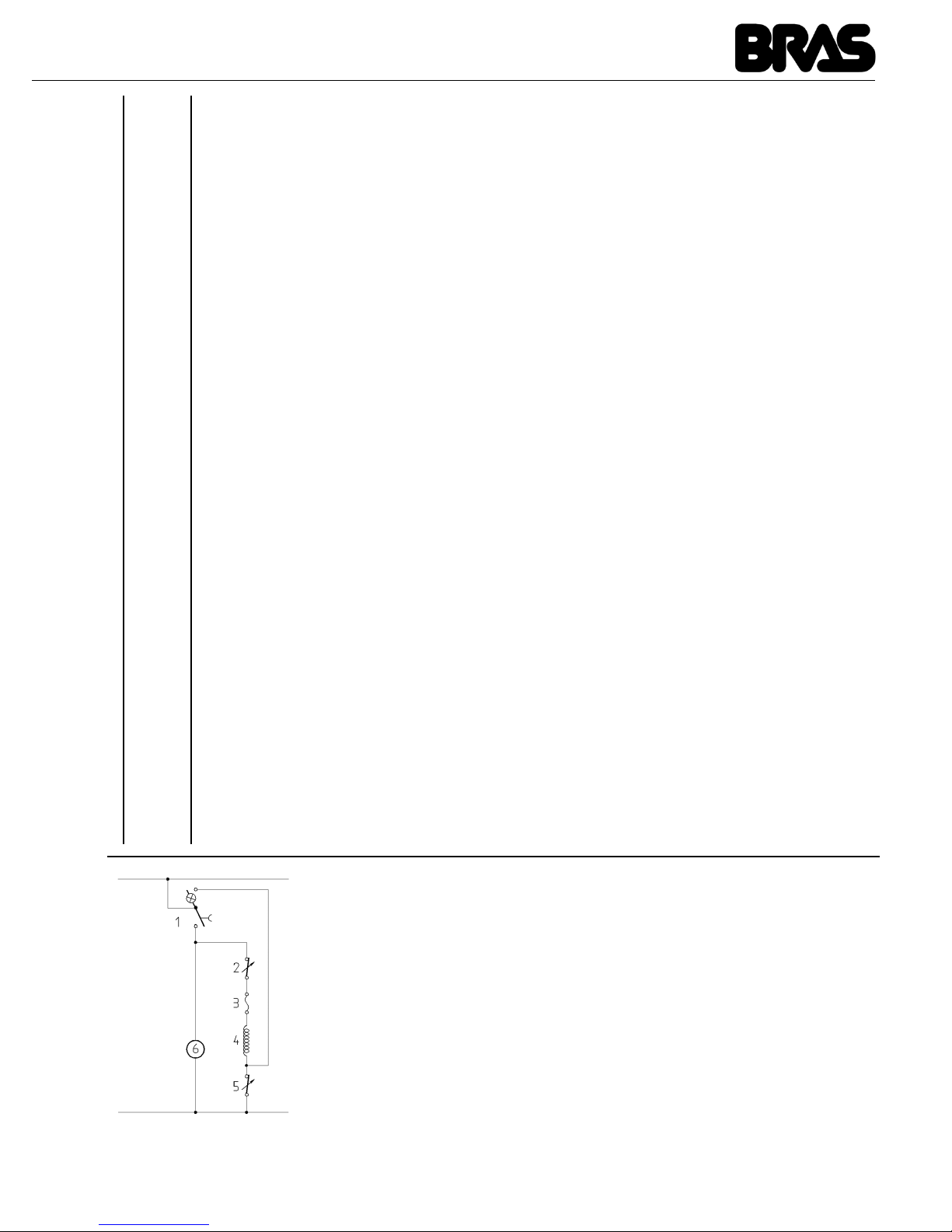
41
7 22800-26426 Termostato di sicurezza Limit switch Thermolimiteur Sicherung Fusible de seguridad
8 22092-00012 Motoriduttore 220/230V 50 Hz Complete gear motor Motoréducteur complet Getriebmotor Motorreductor completo
8 22092-00014 Motoriduttore 115V 60 Hz Complete gear motor Motoréducteur complet Getriebmotor Motorreductor completo
8 22092-00015 Motoriduttore 240V 50 Hz Complete gear motor Motoréducteur complet Getriebmotor Motorreductor completo
9 22800-26463 Pannello laterale Side panel Panneau latéral Seitenteil Panel lateral
9 22800-26433 Pannello laterale “oro” Side panel gold Panneau latéral or Goldfarbig Seitenteil Panel lateral oro
9 22800-26438 Pannello laterale ”argento” Side panel silver Panneau latéral argent Silberfarbig Seitenteil Panel lateral plata
10 22800-26461 Corpo macchina Cabinet Carrosserie Korpus Cuerpo maquina
10 22800-26431 Corpo macchina “oro” Golden cabinet Carrosserie doré Goldfarbig korpus Cuerpo maquina oro
10 22800-26436 Corpo macchina ”argento” Silver cabinet Carrosserie -”argent” Silberfarbig Korpus Cuerpo maquina plata
11 22800-26462 Pannello lato comandi Side panel for controls Panneau latéral pour contrôles Seitenwand mit Bedie-
neinheit
Panel lateral completo de
mandos
11 22800-26432 Pannello lato comandi “oro” Side panel for controls gold Panneau latéral pour contrôles orGoldfarbig Seitenteil mit
Bedieneinheit
Panel lateral completo de
mandos oro
11 22800-26437 Pannello lato comandi
”argento”
Side panel for controls
silver
Panneau latéral pour contrôles
argent
Silberfarbig Seitenteil mit
Bedieneinheit
Panel lateral completo de
mandos plata
12 22800-24301 Interruttore Switch Interrupteur Wegeschalter Interruptor
13 22037-00000 Termostato 5-95°C 5-95°C thermostat Thermostat 5-95°C Thermostat 5-95°C Termóstato 5-95°C
14 22037-00001 Termostato 5-125°C 5-125°C thermostat Thermostat 5-125°C Thermostat 5-125°C Termóstato 5-125°C
15 22800-26460 Basamento Base Base Grundplatte Base
15 22800-26430 Basamento -“oro” Base -“gold” Base -“or” Goldfarbige Grundplatte Base -”oro”
15 22800-26435 Basamento -”argento” Base -”silver” Base -”argent” Silberfarbige Grundplatte Base -”plata”
16 22800-26417 Piedino in gomma Rubber leg Petit pied Justifüße Pie de goma
17 22500-01900 Griglia cassetto Drip tray cover Couvercle tiroir égouttoir Tropfgitter Rejilla cajón recoge-gotas
18 22800-26464 Cassetto Drip tray Tiroir égouttoir Tropfensammelschub Bandeja goteo
18 22800-26434 Cassetto -“oro” Drip tray gold Tiroir égouttoir or Goldfarbig Tropfensammel-
schub
Bandeja goteo oro
18 22800-26439 Cassetto -”argento” Drip tray silver Tiroir égouttoir argent Silberfarbig Tropfensam-
melschub
Bandeja goteo plata
19 22800-05500 Passabloccacavo Cable clamp Borne Anschlußklemme m. Kabe-
leinfürung
Pasacable
20 22500-02000 Pomello per coperchio Cover knob Pommeau du couvercle Deckelgriff Pomo para tapa
21 22800-26409 Coperchio Bowl cover Couvercle du réservoir Deckel Tapa contenedor
21 22800-26429 Coperchio oro Golden bowl cover Couvercle du réservoir doré Goldfarbig Deckel Tapa contenedor oro
22 22800-26414 Mescolatore Mixer Mélangeur Rührwerk Mezclador
23 22800-26412 Albero contenitore Bowl shaft Arbre du réservoir Zentralwelle Arbol del contenedor
24 22800-26419 OR albero centrale Bowl shaft O-ring OR de l’arbre du réservoir O-ring für Zentralwelle OR para àrbol central
25 22800-26407 Fondo contenitore Bowl bottom plate Fond du réservoir Behältergrundplatte Fondo del contenedor
26 10533-03005 Dado albero centrale Central shaft nut Ecru arbre du réservoir Zentralspindel Dado para eje central
27 22800-26410 Guarnizione Bowl gasket Joint du réservoir Behälterdichtung Junta contenedor
28 22800-14801 Pistone per rubinetto Faucet piston Piston du robinet Kolben für Hahn Pistón del grifo
29 22800-15100 OR per rubinetto Faucet piston O-ring Joint OR du robinet O-ring für Piston Junta OR del grifo
30 22700-01860 Leva rubinetto verde Green faucet handle Levier de débit vert Zapfhebel Palanca grifo
30 22700-01801 Leva rubinetto nera Black Faucet handle Levier de débit noir Zapfhebel Palanca grifo
31 22800-26424 Molla rubinetto Faucet spring Ressort du robinet VentilFeder Muelle del grifo
32 22800-22161 Perno verde per leva Green faucet handle pin
Pivot vert pour levier de débit
Fixierstift (grün) Pivote verde de la palanca
32 22800-22160 Perno nero per leva Black faucet handle pin Pivot noir pour levier de débit Fixierstift (scharwz) Pivote negro de la palanca
grifo
33 22800-26405 Contenitore trasparente Bowl Réservoir Behälter Contenedor
34 22800-26418 OR per contenitore Bowl O-ring OR du réservoir O-ring für Behälter OR del contenedor
35 33800-09901 Contenitore completo di fondo Bowl assembly Réservoir complet avec fond Behälter mit Boden aus
Edelstahl
Contenedor completo
36 22001-00001 Flangia motoriduttore Gear motor flange Bride pour motoréducteur Antriebsflansch Brida para motorreductor
38 22800-26413 Albero centrale Central shaft Arbre central Zentralwelle Eje central
39 22800-26466 Ghiera Tap ring Mancon Hahnenzwinge Fijador
40 22800-26458 Manopola termostato 5-95 °C Thermostat knob 5-95 °C
Pommeau du thermostat Drehknopf für Thermostat Pomo para termostato
40 22800-26456 Manopola termostato 32-194 F Thermostat knob 32-194F
Pommeau du thermostat
Drehknopf für Thermostat
Pomo para termostato
41 22800-26459 Manopola termostato 5-125 °C Thermostat knob 5-125 °C
Pommeau du thermostat Drehknopf für Thermostat Pomo para termostato
41 22800-26457 Manopola termostato 32-248 F Thermostat knob 32-248 F
Pommeau du thermostat
Drehknopf für Thermostat
Pomo para termostato
SCHEMA ELETTRICO / WIRING DIAGRAM / SCHEMA ELECTRIQUE / SCHALTSCHEMA / ESQUEMA ELECTRICO
1 Interruttore Switch Interrupteur Dreiwegeschalter Interruptor
2 Termostato 5-125°C 5-125°C Thermostat Thermostat 5-125°C Thermostat 5-95°C Termóstato 5-125°C
3 Termolimitatore 152°C Limit switch 152°C Thermolimiteur 152°C Sicherung 152°C Fusibile de seguridad
4 Resistenza Resistance Resistance Heizung Resistencia
5 Termostato 5-95°C 5-95°C Thermostat Thermostat 5-95°C Thermostat 5-95°C Termóstato 5-95°C
6 Motoriduttore agitatore Gear motor Motoréducteur Motoruntersetzung Motoreductor
Page 42
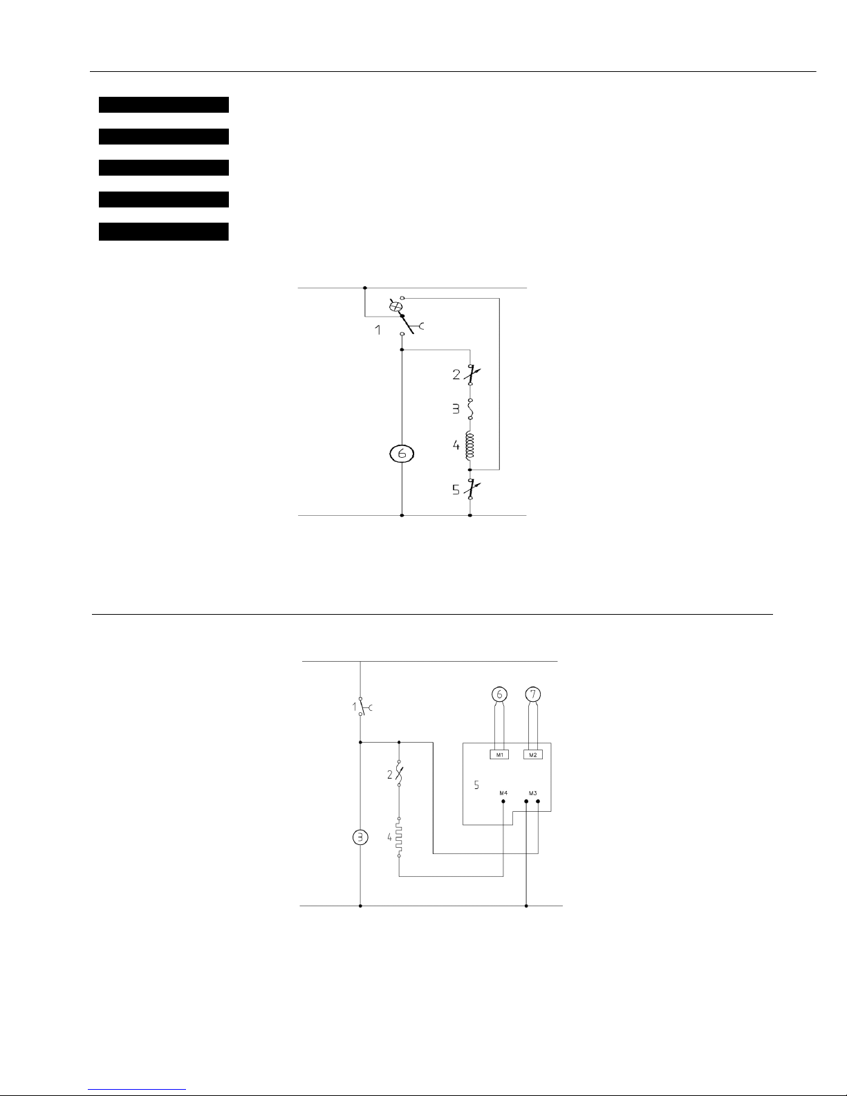
SCIROCCO
42
SCHEMA ELETTRICO
WIRING DIAGRAM
SCHEMA ELECTRIQUE
SCHALTSCHEMA
ESQUEMA ELECTRICO
NORMAL VERSION
1 Interruttore Switch Interrupteur Dreiwegeschalter Interruptor
2 Termostato 125°C 125°C Thermostat Thermostat 125°C Thermostat 125°C Termóstato 125°C
3 Termolimitatore 165°C Limit switch 165°C Thermolimiteur 165°C Sicherung 165°C Fusibile de seguridad
4 Resistenza Resistance Resistance Heizung Resistencia
5 Termostato 5-95°C 5-95°C Thermostat Thermostat 5-95°C Thermostat 5-95°C Termóstato 5-95°C
6 Motoriduttore agitatore Gear motor Motoréducteur Motoruntersetzung Motoreductor
ITALIANO
ENGLISH
FRANCAIS
DEUTSCH
ESPAÑOL
ELECTRONIC VERSION
1 Interruttore Switch Interrupteur Dreiwegeschalter Interruptor
2 Termofusibile Termic fuse
3 Motoriduttore Gear motor Motoréducteur Motoruntersetzung Motoreductor
4 Resistenza Resistance Resistance Heizung Resistencia
5 Controllo elettonico Electronic device Circiut imprimé de contrôle Elektronik Circuito electronico
6 Sensore temperatura prodotto Product temperature sensor Sonde de température de
produit
ProduktTemperaturfühler Sensor de temperatura del
producto
7 Sensore temperatura resistenza Resistance temperature sensor Sonde de température de
résistance
Widerstand
Temperaturfühler
Sensor de temperatura de la
resistencia
02451-00099 V 0.2 15E18
Page 43
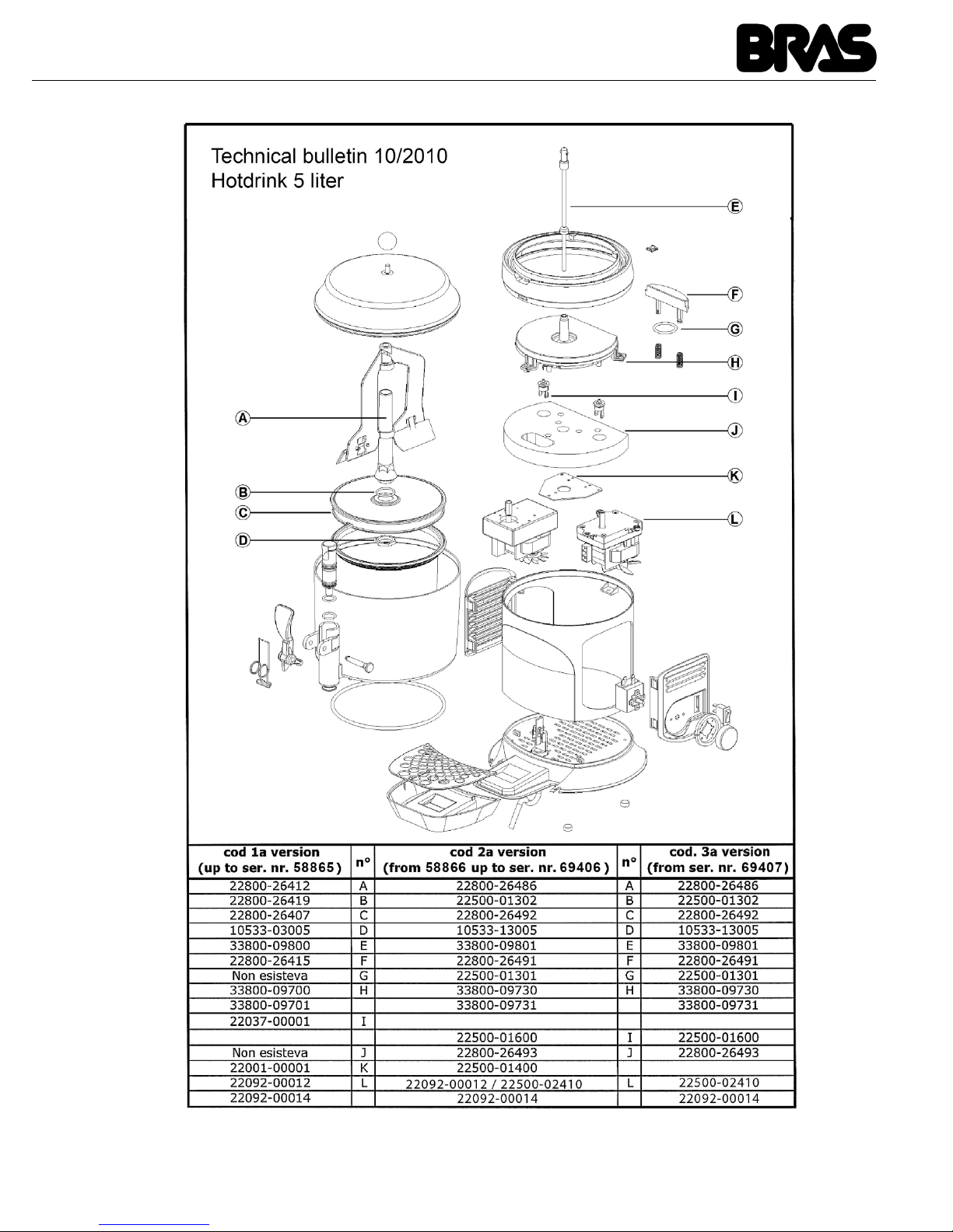
43
Page 44
02451-00099
R5.8 16A22
 Loading...