

Brant Radiant Heaters LS series Operation, Installation & Maintenance Instructions [en, fr]
Page 1
LS SERIES
COMMERCIAL, INDUSTRIAL, RESIDENTIAL
TUBE HEATER
OPERATION, INSTALLATION, MAINTENANCE
AND PARTS MANUAL
REVISIONS:
FORWARD STATEMENT VENT PLACEMENT- pg. 18, Jan 07
½”
TYPE I HOSE CONNECTORS- pg. 22 Jan 07
WARNING:
If the information in these instructions are not
followed exactly, a fire or explosion may result
causing property damage, personal injury or loss
of life.
FOR YOUR SAFETY!
FOR YOUR SAFETY!
IF YOU SMELL GAS:
IF YOU SMELL GAS:
1. Open windows.
1. Open windows.
2. Do not touch electrical switches.
2. Do not touch electrical switches.
3. Extinguish any open flame.
3. Extinguish any open flame.
4. Immediately call your gas supplier.
4. Immediately call your gas supplier.
Do not store or use gasoline or flammable
vapours and liquids in the vicinity of this or
any other appliance.
Jan 07
AVERTISSEMENT:
Assurez-vous de bien suivre les instructions
données dans cette notice pour réduire au
minimum le risque d’incendle ou d’explosion ou
pour éviter tout dommage matérial, toute blessure
ou la mort.
CONSIGNES DE SÉCURITÉ !
CONSIGNES DE SÉCURITÉ !
SI VOUS SENTEZ UNE ODEUR DE GAZ:
SI VOUS SENTEZ UNE ODEUR DE GAZ:
1. Ouvrez les fenêtres.
1. Ouvrez les fenêtres.
2. Ne touchez pas aux interrupteurs électriques.
2. Ne touchez pas aux interrupteurs électriques.
3. Éteignez toute flamme nue.
3. Éteignez toute flamme nue.
4. Contactez immédiatement votre compagnie
4. Contactez immédiatement votre compagnie
de gaz.
de gaz.
Il est interdit d’utiliser des liquides inflammables
ou dégageant des vapeurs infammables, à
proximité de tout appariel fonctionnant au gaz.
Form #LS0307
Page 2
FORWARD
WARNING
If the information in these instructions are not followed exactly, a fire or explosion may
result causing property damage, personal injury or loss of life.
- Do not store or use gasoline or other flammable vapors or liquids in the vicinity of this or
any other appliance.
- WHAT TO DO IF YOU SMELL GAS
-Do not try to light any appliance
-Do not touch any electrical switch; do not use any phone in your building
-Immediately call your gas supplier from a neighbor’s phone. Follow the gas
supplier’s instructions.
-If you cannot reach your gas supplier, call the fire department.
- Installation and service must be performed by a qualified installer, service agency or the
gas supplier.
INSTALLER
CONSUMER
Brant Radiant Heaters Limited heaters are design
certified by the CSA International and comply
™Trade-mark of Canadian Standards Association
: Leave this manual with the appliance.
: Retain this manual for future reference.
Approval Standards and Certifications
with the National Standards of Canada.
CAUTION
ANY ALTERATION OF THIS SYSTEM OR OF THE FACTORY-AUTHORIZED
COMPONENTS AS SPECIFIED IN THIS MANUAL OR BY BRANT RADIANT
HEATERS LIMITED VOIDS ALL CERTIFICATIONS AND WARRANTIES.
P.O. Box 395, 34 Scott Avenue - Paris, Ontario N3L 3T5 - Telephone: (519) 442-7823
Fax: (519) 442-7321 - Customer Service: 1-800-387-4778
Brant Radiant Heaters Limited
www.brantradiant.com
Page 3

1. SAFETY INFORMATION
2. INSTALLATION
2.1 Design Criteria
2.2 Prechecks
2.3 Heater Hanging
2.4 Tube Assembly
2.41 Baffle Assembly
2.5 Reflector Assembly
2.6 Optional Side Shield Installation
2.7 Optional Exchanger “L” or “U” Configuration
2.8 Flue Venting
2.9 Installation for Unvented Operation (Optional)
2.10 Combustion Air Requirements
2.11 Gas Supply
2.12 Allowance for Expansion
2.13 Electrical Requirements
2.14 Lighting Instructions
2.15 Shutdown Instructions
3. THEORY OF OPERATION
TABLE OF CONTENTS
3.1 LS Single-stage Models
4. SERVICE
4.1 Maintenance
4.2 Access Panels
4.3 Thermal Limit Switch
4.4 Service
4.5 General Troubleshooting
5. PARTS LIST
5.1 Basic Part List
5.2 Optional Parts
1
Page 4
1 SAFETY INFORMATION
WARNING
This is not an explosion-proof heater. Where there is the possibility of exposure to flammable vapors, consult
the local fire marshal, the fire insurance carrier or other authorities for approval of the proposed installation.
This infra-red heater is designed for use in industrial and commercial buildings such as warehouses,
manufacturing plants, aircraft hangars, service garages, etc. and residential applications such as garages,
solariums, swimming pools, etc.
Brant Radiant Heaters Limited cannot anticipate every use which may be made of their heaters. Check with
your local gas supplier if you have questions about local regulations.
CAUTION
The following information should be reviewed before installing this heater:
* Check the CSA rating label on the heater to verify the minimum clearances to combustibles and the
proper gas to be used.
* The installation of this heater must conform with local building codes or, in the absence of local codes,
with the current CAN/CSA B149.1 and 2 Codes and with the Canadian Electrical Code C22.1-latest
edition.
* In public garages the heaters must be installed in accordance with the Canadian Electrical Code C22.1-
latest edition when an external electrical source is utilized.
* This is not an explosion-proof heater. Where there is the possibility of exposure to flammable
vapors, consult local fire marshall or other authorities for approval of the proposed installation.
* In aircraft hangars, the heater must be installed at least ten feet (3 m) above the upper surface of wings
or engine enclosures of the highest aircraft which may be stored in the hangar. In areas adjoining the
aircraft storage area, the heaters must not be installed less than eight feet (2.4 m) above the floor. Also, the
heaters must be located to prevent damage to the sections of the aircraft, cranes, scaffolds or other
movable objects.
* Under no circumstances is either the gas supply line or the electrical supply line to the heater to provide
any assistance in the suspension of the heater.
* The weight of the heater must be entirely suspended from a permanent part of the building structure
having adequate load characteristics.
* Neither the gas supply line, electrical supply line nor sprinkler heads shall be located in or near the path
of the flue products from the heater.
* If wind conditions in the space are such that visible swaying of the heater is apparent, the control box
must be rigidly mounted.
* If chlorinated or fluorinated contaminants are present in the area where the heater is installed, then
noncontaminated air for combustion must be ducted to the heater. Sources of contaminants are
refrigerants, solvents, adhesives, paints, degreasers, paint removers, lubricants, pesticides, etc.
* If vaporized solvents are allowed to contact the heater’s HOT exchanger tube, noxious fumes may
result. Chemicals must be properly stored, per manufacturers instructions. Ventilation requirements, as
outlined by local codes, must be maintained.
* Signs should be posted in storage areas to specify maximum stacking height allowed in order to
maintain clearance to combustibles.
2
Page 5
1 SAFETY INFORMATION
WARNING WARNING
Failure to comply with the stated clearance to
combustibles could result in personal injury,
death and/or property damage.
This heater should be installed so that the
minimum clearances to vehicles, as marked on
the heater, will be maintained. If vehicles lifts are
present, ensure that these clearances will be
maintained from the highest raised vehicle.
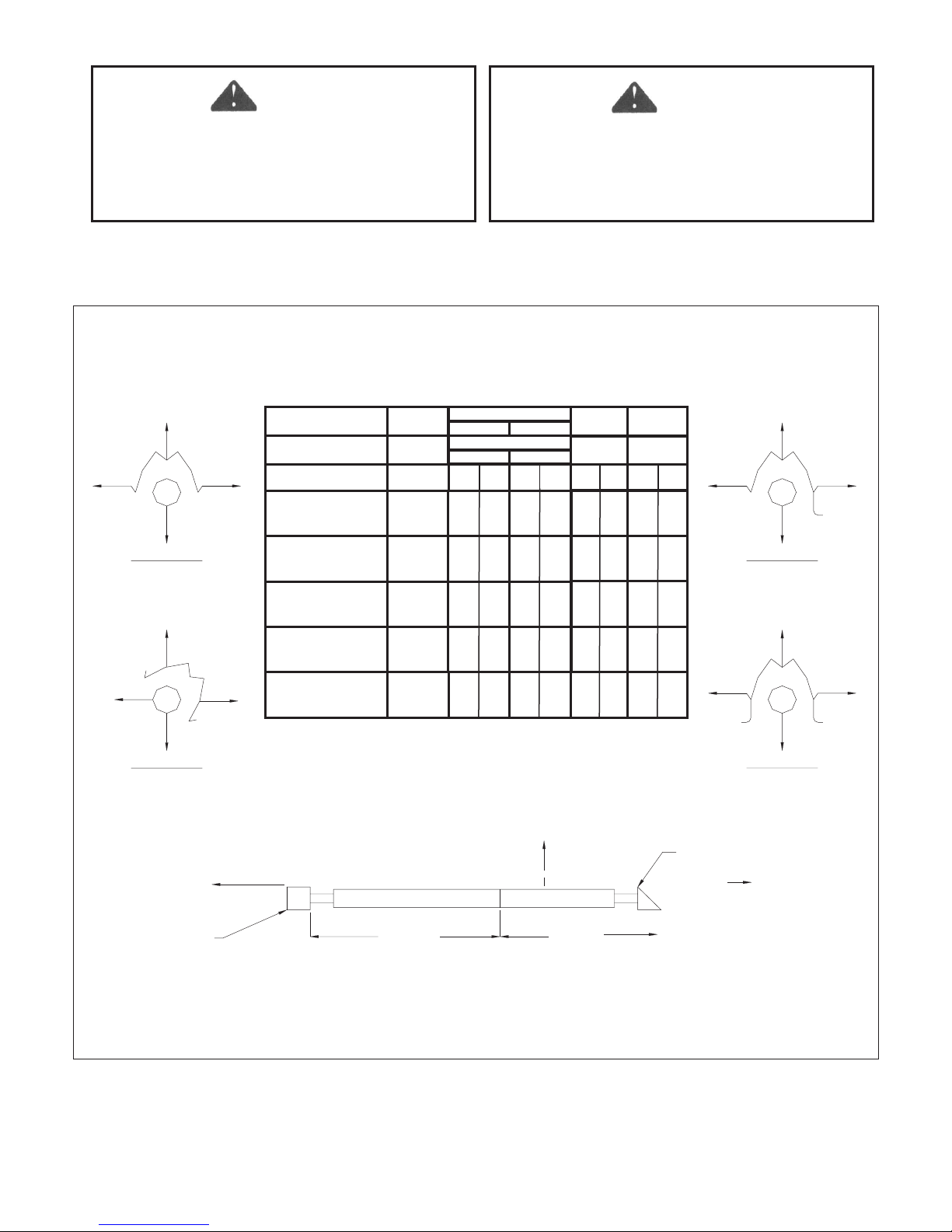
For the safe installation of this heater, the following table contains clearances that must be maintained:
CLEARANCES TO COMBUSTIBLES IN. & CM / DÉGAGEMENTS AUX MATIÈRES COMBUSTIBLES PCE & CM
TOP
SIDE
BELOW
0° MOUNTING ANGLE
TOP
FRONT
SIDE
BEHIND
MODEL NO.
MODÈLES
UNITS
LS(10,15)-25 (N, P)
W/1 SIDE SHIELD
W/2 SIDE SHIELDS
LS(10,15)-30 (N, P)
W/1 SIDE SHIELD
W/2 SIDE SHIELDS
LS(10,15,20)-40 (N, P)
W/1 SIDE SHIELD
W/2 SIDE SHIELDS
LS(15,20,30)-50 (N, P)
W/1 SIDE SHIELD
W/2 SIDE SHIELDS
20 ft or 6.1 m
DOWNSTREAM
OF BURNER
MOUNTING
ANGLE
ANGLE DE
MONTAGE
DEGREES
0°
45°
0°
0°
0°
45°
0°
0°
0°
45°
0°
0°
0°
45°
0°
0°
0°
BEHIND
ARRIÈRE
IN.
PCE
CM
20.3
8
20.3
8
20.3
8
22.9
9
20.3
8
20.3
8
20.3
8
22.9
9
38.1
15
20.3
8
20.3
8
50.8
20
27.9
11
20.3
8
20.3
8
40.6
16
17.8
7
SIDE
IN FRONT
CÔTE
AVANT
IN.
PCE
39
29
39
29
15
58
42
20
11
39
29
16
TOP
DESSUS
IN.
PCE
CM
20.3
99.1
73.7
22.9
20.3
99.1
73.7
22.9
38.1
147.3
106.7
50.8
27.9
99.1
73.7
40.6
17.8
4
10
4
4
4
10
4
4
6
10
6
6
6
10
6
6
6
8
9
8
9
7
CM
10.2
25.4
10.2
10.2
10.2
25.4
10.2
10.2
15.2
25.4
15.2
15.2
15.2
25.4
15.2
15.2
15.2
BELOW
DESSOUS
IN.
PCE
CM
91.4
36
91.4
36
91.4
36
91.4
36
91.4
36
91.4
36
91.4
36
91.4
36
114.3
45
114.3
45
114.3
45
114.3
45
121.9
48
121.9
48
121.9
48
121.9
48
77
30
SIDE
SIDE
TOP
BELOW
0° W/1 SIDE SHIELD
TOP
SIDE
SIDE
BELOW
45° MOUNTING ANGLE
BURNER
NOTE: The LS-10-40 N or P models are
NOT APPROVED FOR RESIDENTIAL USE.
MIN. 12 IN.or 30.5 cm
END CLEARANCE
FIRST 20 ft
or 6.1 m
TO CEILING
20 ft or 6.1 m
DOWNSTREAM
& BEYOND
Shielded Accessory Exchanger Elbows or “U” Bends do not alter clearances
Unshielded Elbow or “U” Bend Top Clearance is 18” or 45.7 cm
3
BR-VCF
12 IN. or 30.5 cm
CLEARANCE
TO WALL OR
COMBUSTIBLES
BELOW
0° W/2 SIDE SHIELDS
Page 6
1 SAFETY INFORMATION
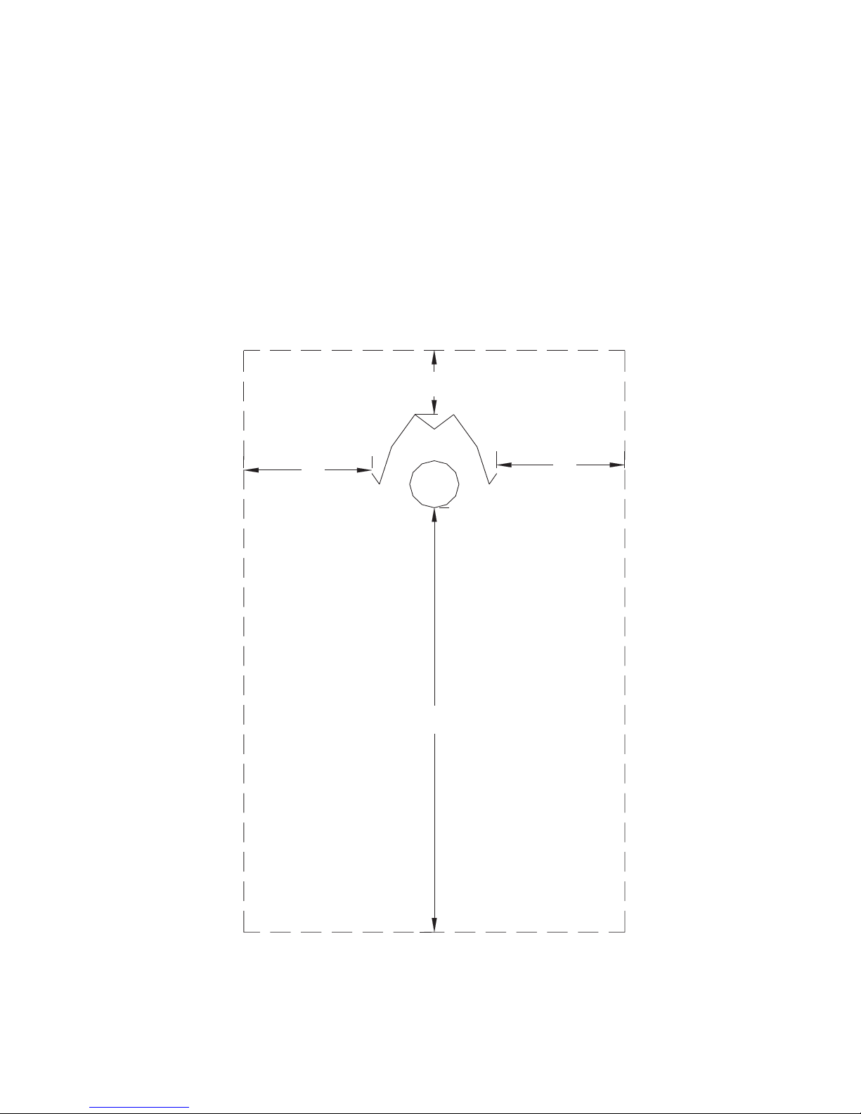
The clearance-to-combustible measurements represent an alcove or clearance box with vertical and horizontal
planes. See figure 1.1.
Example: LS-15-30 clearances as stated at 0° mounting- Top 4” or 10.2cm
Side 8” or 20.3cm
Below 36” or 91.4cm
Note: Combustible material MUST NOT be placed within the confines of the clearance box.
Observe all WARNINGS listed in installation instructions and stated on heater control box.
TOP
90° + Ambient
4”
10.2cm
SIDE
90° + Ambient
8”
20.3cm
36”
91.4cm
8”
30.3cm
SIDE
90° + Ambient
BELOW
90° + Ambient
Figure 1.1
4
Page 7
2INSTALLATION
2.1 Design Criteria
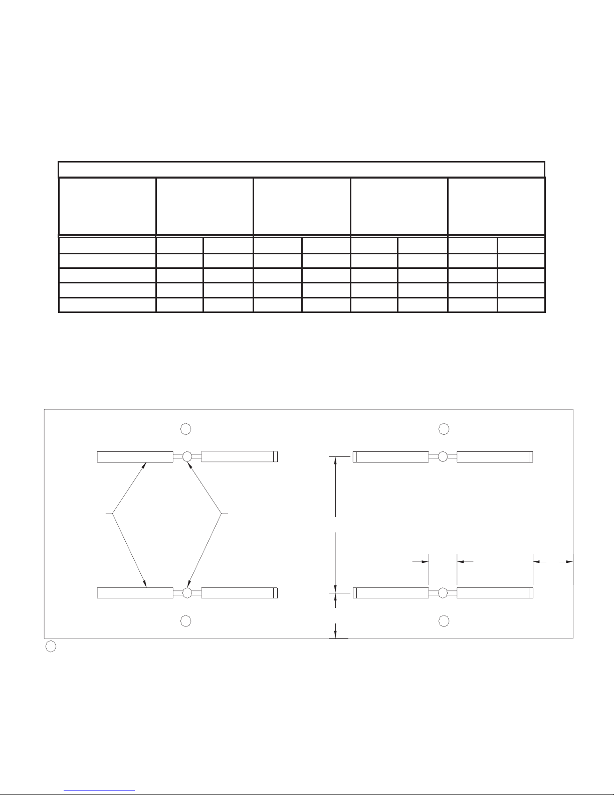
Perimeter mounting of these infra-red heaters
provides for the most efficient installation. In figure
2.1.1, the heaters are mounted at the perimeter of the
space to be heated. Refer to the Heater
the models being installed. Buildings that require the
rows of heaters to be farther apart than the
recommended distance in the chart may need
additional heaters placed in the center of the space.
Installation Chart for the recommended distances on
HEATER INSTALLATION CHART
DISTANCE
BETWEEN
HEATER ROWS
DIM “B”
FT.
8-40
9-45
10-50
12-60
MODEL
NO.
UNITS
LS (10, 15) 25 (N, P)
LS (10, 15) 30 (N, P)
LS (10, 15, 20) 40 (N, P)
LS (15, 20, 30) 50 (N, P)
TYPICAL
MOUNTING
HEIGHT
FT.
7-14
8-15
9-16
10-17
METERS
2.1-4.3
2.4-4.6
2.7-4.9
3.0-5.2
DISTANCE
BETWEEN
HEATERS
DIM “A”
FT.
6-22
8-24
9-26
10-28
METERS
1.8-6.7
2.4-7.3
2.7-7.9
3.0-8.5
Note: This chart is provided as a guideline. Actual conditions may dictate variation from this data.
METERS
2.4-12.2
2.7-13.7
3.0-15.2
3.7-18.3
MAXIMUM DISTANCE
BETWEEN HEATER
AND WALL
DIM “C”
FT.
13
14
15
16
METERS
4.0
4.3
4.6
4.9
INFRARED
HEATER
(TYPICAL)
T
THERMOSTAT
TT
COMMON
VENT
B
(TYPICAL)
A
TT
C
C
Figure 2.1.1
TYPICAL BUILDING LAYOUT
5
Page 8

When positioning heaters, keep in mind the
clearances to combustible materials, lights, sprinkler
heads, overhead doors, storage areas with stacked
materials, gas and electrical lines, parked vehicles,
cranes and any other possible obstructions or
hazards. Refer to the Warnings, Cautions and the
Clearance-To-Combustibles Chart in the Safety
Information Section and on the heater to verify that a
safe installation condition exists.
* Outside air for combustion must be ducted to the
heater if the building atmosphere where the heater
is installed contains one of the following:
- Chemicals such as chlorinated or fluorinated
hydrocarbons.
- High humidity such as car washes.
- Contaminants such as sawdust, welding
smoke, etc.
- Negative static pressure.
The following guidelines must also be met to ensure
a good installation and proper heater performance:
* A maximum of two 45 degree elbows, two 90 degree
Consult Combustion Air Requirements section on
page 20.
* Do not exceed the maximum air intake duct length of
elbows or one 180 degree elbow can be installed on
heaters. The gas input of the heaters, as stated on
the rating label, will determine the minimum length
* Do not draw fresh air to the heater from an attic
of radiant pipe from the control box to the first elbow.
(See Optional 45, 90 and 180 degree Elbows section
on page 14.)
NOTE: Flue vent requirements do not change when
* All unvented heaters must use a vent with flapper,
elbows are installed.
* Do not exceed the maximum vent length of 20 ft./6.1m
for exhausting the heater. Consult Flue Venting,
Once all of the safety precautions and design criteria
are met, the actual installation of the heater may begin.
Section 2.8.
* Do not combine the exhaust vents of two heaters
into a straight-through tee. A Part Number DB-3YA,
or staggered-tee arrangement must be used. Heaters
sharing the same vent must share the same thermostat.
Common vents must have 4 in./10.2cm Diameter ( see Figure 2.1.1).
35 ft./10.7m. Consult Air Intake Duct Chart on page 20.
space. There is no guarantee that adequate air will
be supplied. Prevailing winds can create negative
or positive pressure in the space.
Part Number DB-3VCF.
6
Page 9
2 INSTALLATION
2.2 Prechecks
1. Verify that all parts have been received by checking
them against the packing list. If there are questions
regarding the shipment, notify the Re-Verber-Ray
distributor or Brant Radiant Heaters Limited at
Customer Service- 1-800-387-4778.
2. Check the CSA rating label located on the heater’s
control box above the inlet gas supply connection,
to verify the model number, gas input and the gas
to be used.
3. Locate the Clearance-To-Combustibles label
affixed to the heater’s access panel/cover. Using
the heater’s model numbers, as displayed on the
rating label, make sure the finished installation
will conform to the design requirements listed on
the label and the Clearance-To-Combustibles
Chart and the figures shown on page 3.
4. Heaters may discharge the combustion-byproducts directly into the heated space when the
conditions in section 2.9 Installation for Unvented
operation have been met.
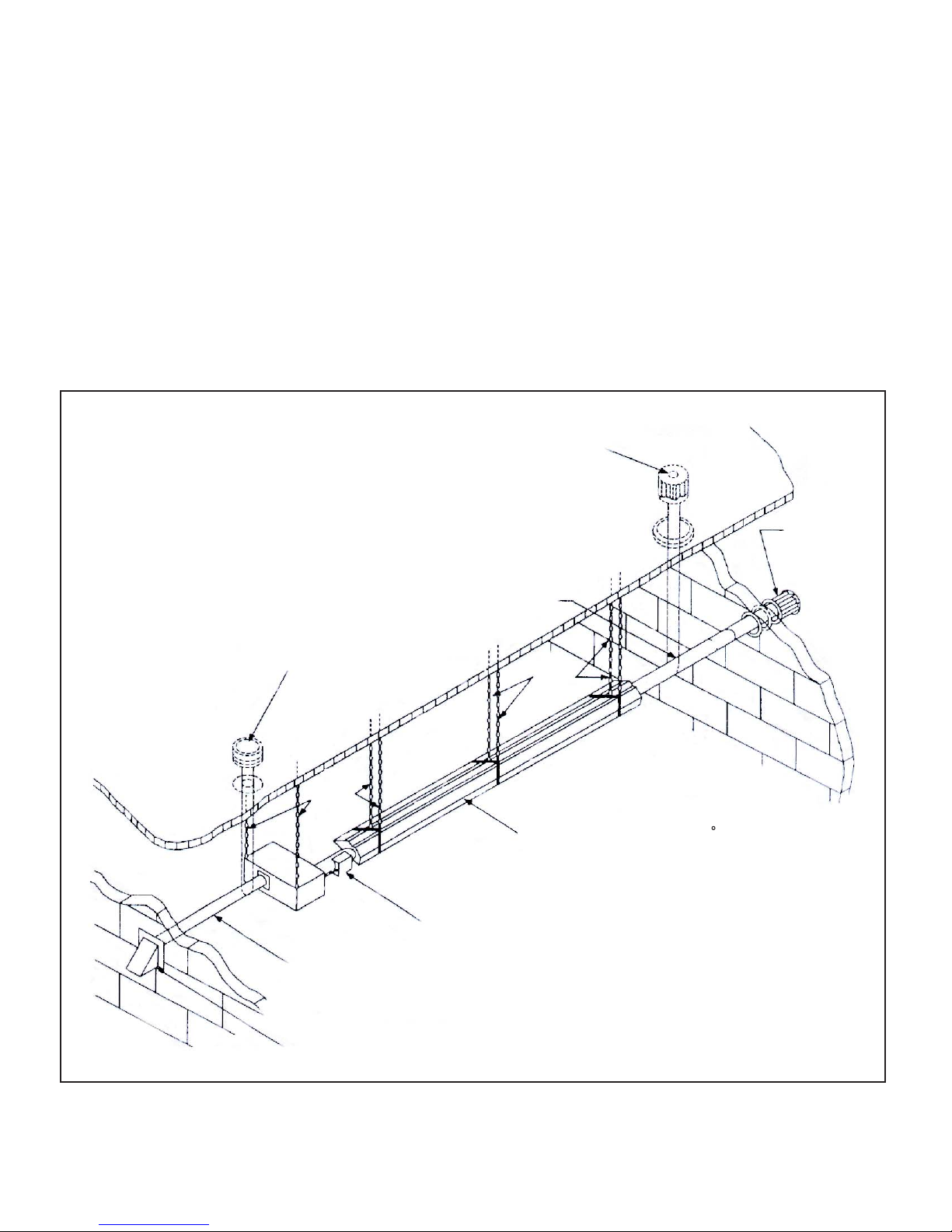
ALTERNATE EXHAUST
(THROUGH ROOF)
EXHAUST
VENT CAP
3 IN./7.6cm DIA. VENT PIPE
ALTERNATE AIR INTAKE
(THROUGH ROOF)
CHAIN
SET
GLO-BAR BOX
AIR INTAKE THROUGH WALL
BR-VC INLET VENT CAP
CHAIN
SET
REFLECTOR (shown at 30 mounting angle)
Figure 2.2.1
TYPICAL INSTALLATION DRAWING
7
Page 10
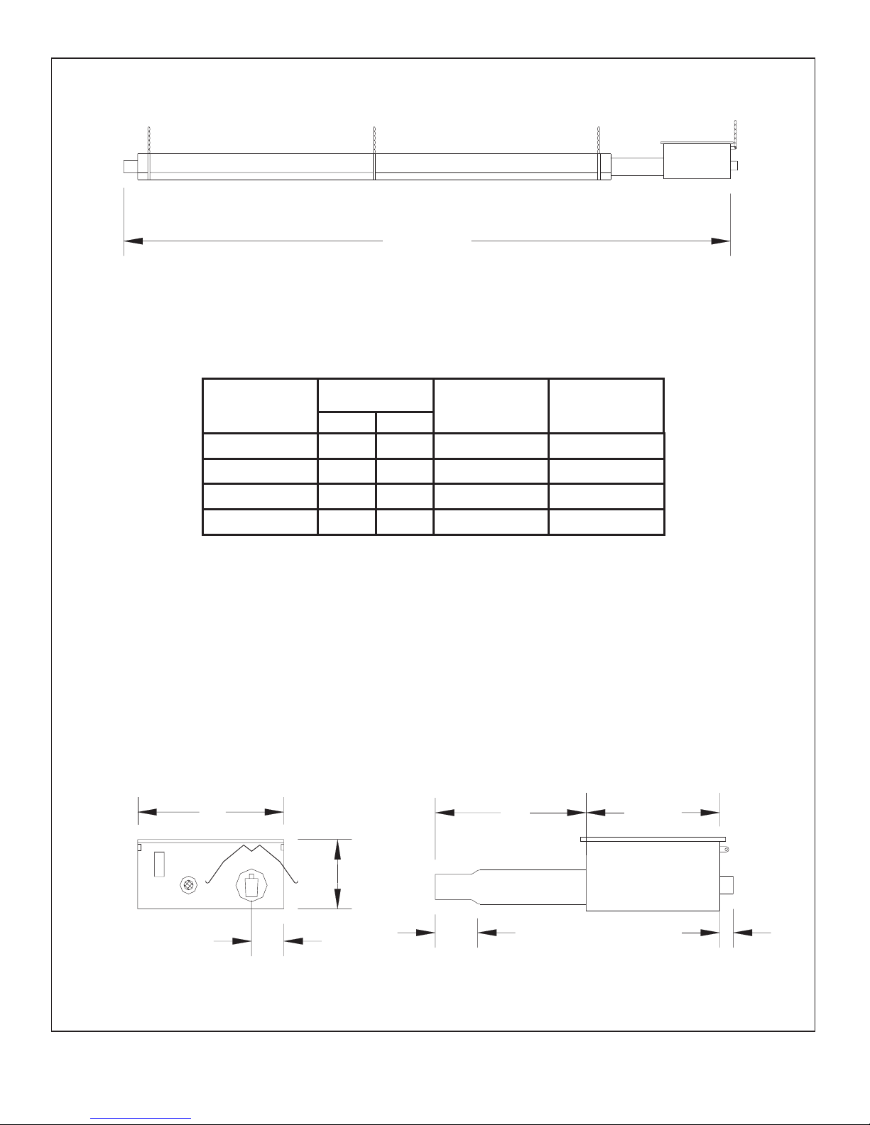
"B"
"B"
"A" DIM
"B"
"C"
MODEL
NUMBER
LS 10
LS 15
LS 20
LS 30
DIMENSION
“A”
IN. M
135
195
258
375
3.4
5.0
6.6
9.5
SUSPENSION
POINTS “B”
2
3
3
4
CONTROL BOX
STABILIZER “C”
2
2
2
2
18"
45.7 cm
5"
12.7 cm
END VIEW
81/8"
20.6 cm
Figure 2.2.2
8
16"
40.6 cm
11 1/8"
28.3 cm
4"
10.2 cm
5.1 cm
ENLARGED SIDE VIEW
2"
Page 11
2 INSTALLATION
2.3 Heater Hanging
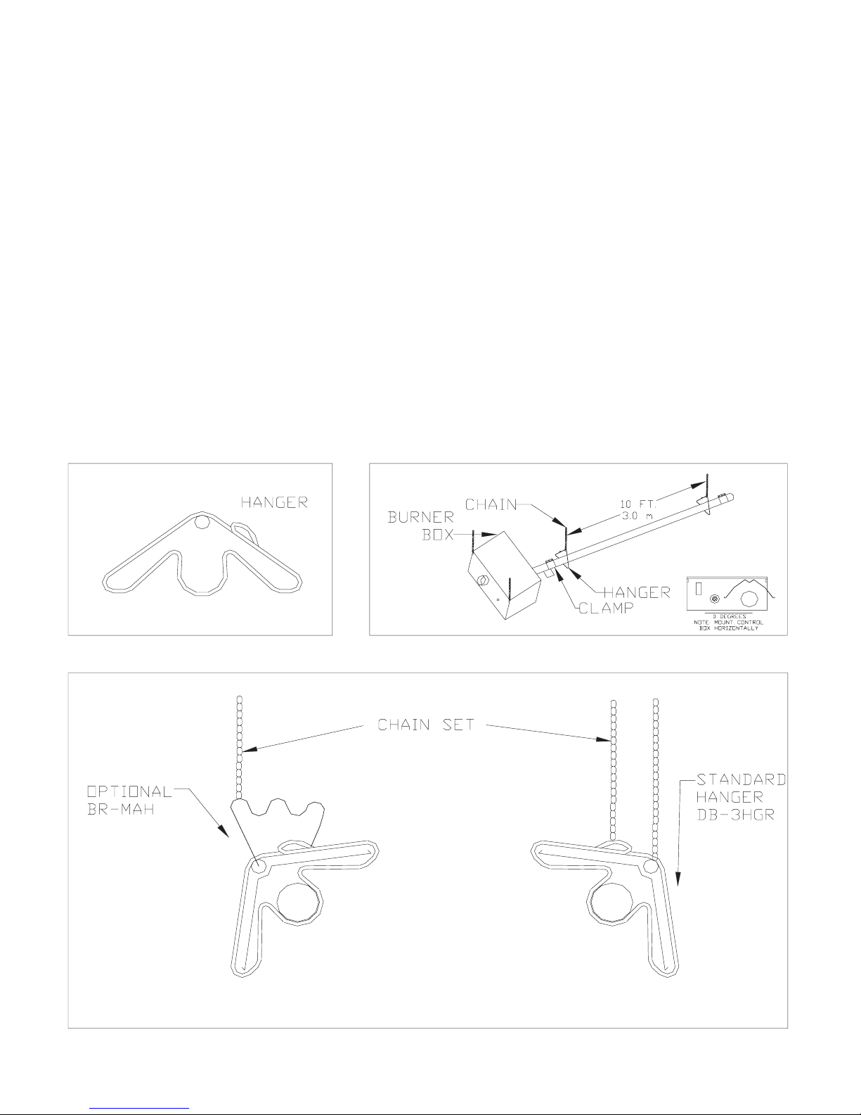
1. The combination tube/reflector suspension
hangers (DB-3HGR), shipped in the parts box
located in the heater control box carton shall be
sufficient to support the heater every 10 feet or 3 m.
Figure 2.3.1
2. Install the heater so that it is independently
supported from the building having adequate load
characteristics. Do not support the heater by the
gas or electrical supply lines.
3. The burner box must be installed so that it is level
and the burner sight glass visible from the floor.
Figure 2.3.2
4. The two hangers supporting the first 10 ft. or 3 m
tube must be installed near the ends of the tube next
to the clamps. It is recommended that the remaining
hangers be installed approximately 10 ft. or 3 m apart.
Figure 2.3.2
5. The suspension chains must be installed so that
they are perpendicular to the heater. When
mounting reflectors at 0 degrees one chain per
hanger is required. When angle mounting the
reflector two chains are required or one chain and
a BR-MAH. Figure 2.3.3
Optional: BR-MAH- An accessory multiple angle
hanger that can be added to preselect the reflector
angle at 15, 30 or 45 degrees.
Optional: BR-CS - An accessory chain set
consisting of 5 ft./1.52m of number 1 double loop
chain and 2 “S” hooks.
6. Close all “S” hooks to ensure maximum load
carrying capacity.
7. If wind conditions in the space are such that
visible swaying of the heater is apparent, the
control box must be rigidly mounted. Threaded
rod can be used to stabilize the control box.
Figure 2.3.1
Figure 2.3.2
Figure 2.3.3
9
Page 12
2 INSTALLATION
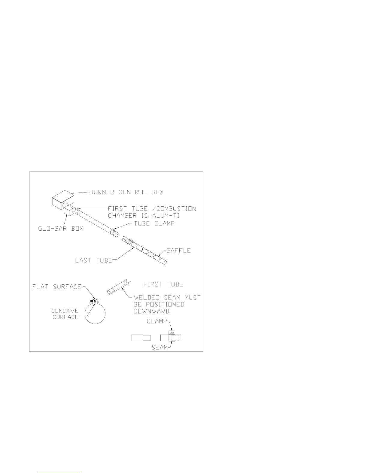
2.4 Tube Assembly
All LS models use highly emissive coated aluminized
titanium steel for combustion tube ( first 10 ft./3.1m).
An aluminized titanium tube is identified by a bright
yellow shipping band. The exchanger tubes are highly
emissive coated aluminized steel.
1. Slide tubes through hangers with welded seam
downwards and locate tube clamp on tube.
2. Mate tubes completely then recheck suspension
hanger locations and secure. Center clamp on
seam and torque clamp bolts to 50 - 60 lbs. - ft.
Figure 2.4.1
3. STOP: Before final assembly of the last radiant
tube verify baffle length, install baffle in the
vertical position and complete final assembly.
See figure 2.4.2 on page 11.
4. Optional: Exchanger configuration 45, 90, 180
degree. Refer to page 14 and 15.
Figure 2.4.1
10
Page 13
2 INSTALLATION
2
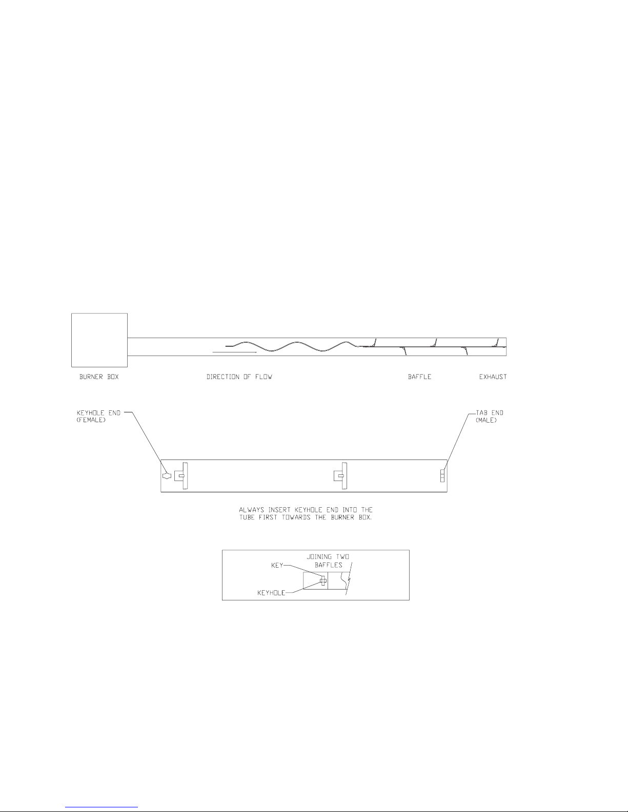
.41 Baffle Assembly
INSTALLATION: BAFFLES MUST BE INSTALLED ACCORDING TO MANUFACTURERS INSTRUCTIONS TO
ENSURE THE HEATERS SAVE AND EFFICIENT OPERATION.
LS, LD, LSA, & LDA models use of heat transfer baffle and of pressure baffle. The pressure baffle
utilizes restrictor tabs that incorporate a factory set angle to optimize heater performance. Baffles must be installed as per
diagram.
When a 45° , 90° elbow, or 180° “U” bend is used to alter the radiant tubing the heat transfer baffle (baffle without ears)
must be removed from the baffle configuration. Install the baffles (baffles with ears) only.
NOTE: The position of the tabs relevant to heater airflow.
- The two pressure baffles must be the last two baffles installed in tube.
- The tabs on pressure baffle must be alternated in assembly for proper performance.
- Refer to drawings for baffle assembly.
one section two sections
two pressure
Figure 2.4.2
11
Page 14
2 INSTALLATION
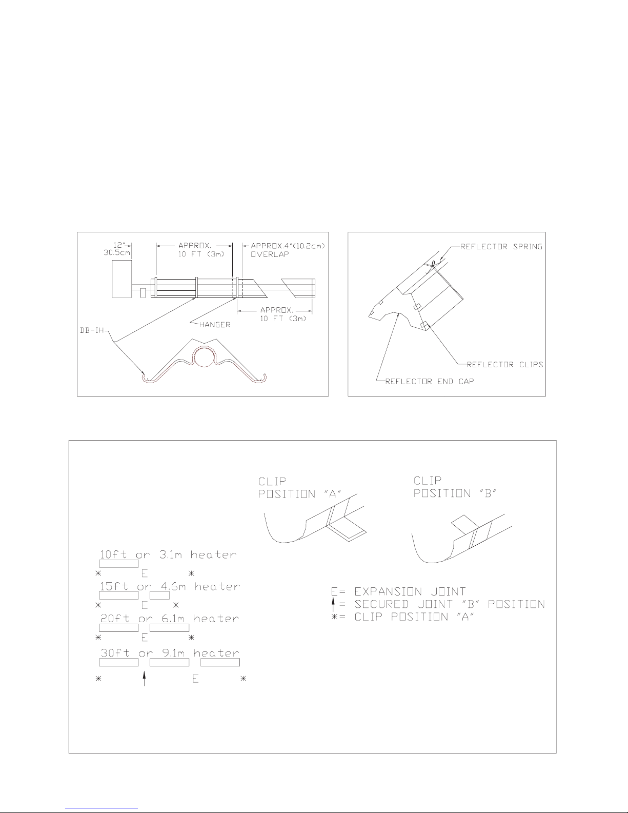
2.5 Reflector Assembly
1. Install reflector intermittent support DB-IH as
shown in figure 2.5.1
2. Slide reflectors through wire suspension hangers
and adjust the reflector positioning spring in the
V-groove on top of the reflector. Figure 2.5.2
3. Overlap reflectors 4 inches/10.2cm for support and
secure together with supplied clips or sheet metal
screws. Make sure to leave an expansion joint as
shown in Figure 2.5.3.
4. Install clips in their “A” position as shown in
Figure 2.5.3 on the first and last suspension
hanger. Clips are located right side front and left
side back of the wire suspension hanger.
5. Optional: Side Shield Installation refer to page 13.
Figure 2.5.1
Figure 2.5.2
Figure 2.5.3
12
Page 15
2 INSTALLATION
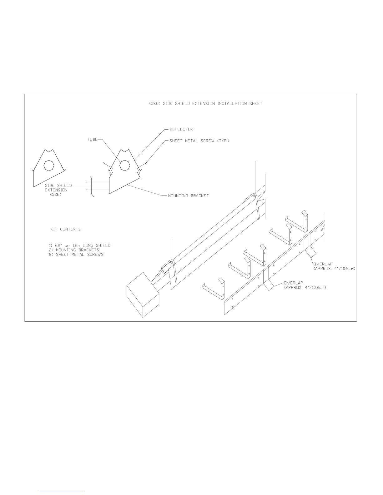
2.6 OPTIONAL
Side Shield Installation
1. Install side shields as per figure 2.6.1. The clearance to
combustibles will be altered when side shields are installed.
Refer to safety information on page 3.
Figure 2.6.1
13
Page 16
2 INSTALLATION
2.7 OPTIONAL
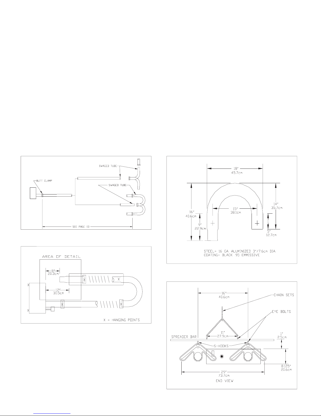
Exchanger “L” or “U” Configuration
A maximum of two 45, 90 degree “L” or one 180
degree “U” bend may be installed to alter the
standard radiant tube configuration (see Figure 2.7.1).
See the Baffle Specification Chart on page 15 for the
minimum distance requirements, listed by model
number from the burner control box to an elbow or
“U”.
DB-45-E consists of a 45 degree 16 Ga. Swaged
elbow, tube clamp and one suspension
hanger.
DB-3EA consists of a 90 degree 16 Ga. Swaged
elbow, tube clamp, two piece reflector
and one suspension hanger.
DB-3UA consists of a 180 degree 16 Ga. Swaged
“U”, tube clamp, three piece reflector,
one suspension hanger and one reflector
support.
Figure 2.7.2 Hanging Points
Figure 2.7.3 “U” Dimensions
Figure 2.7.4 Spreader Bar (optional)
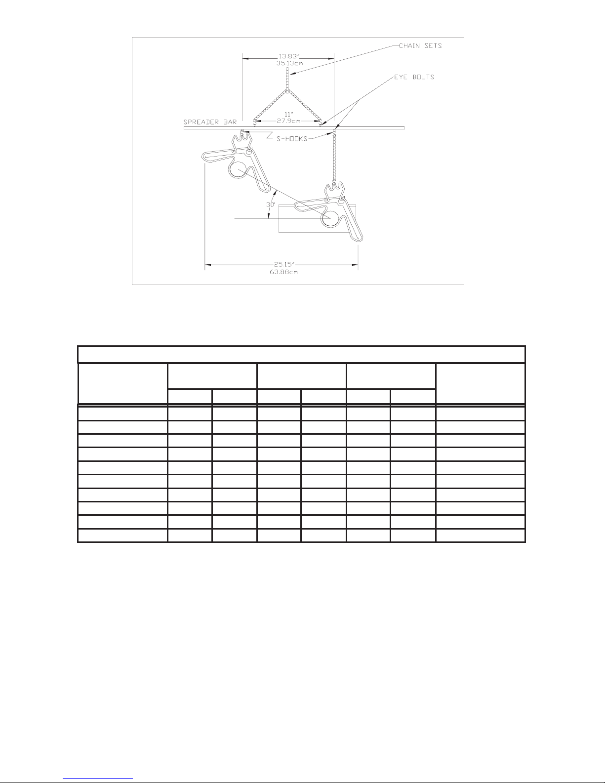
Figure 2.7.5 Spreader Bar (optional)
IMPORTANT
Baffle lengths may be altered with the addition of
elbows or “U” assembly. See BAFFLE
SPECIFICATION CHART on page 15 for baffle
lengths listed by model number.
When utilizing a “U” or “L” bend the exhaust/return
leg must be equal to or higher than the burner control
box. Reflector runs from burner control to elbow or
“U” will require an expansion joint. See page 15.
Figure 2.7.1
Figure 2.7.2
Figure 2.7.3
Figure 2.7.4
14
Page 17
BAFFLE SPECIFICATION CHART
MODEL
NUMBER
LS-10-25 (N, P)
LS-15-25 (N, P)
LS-10-30 (N, P)
LS-15-30 (N, P)
LS-10-40 (N, P)
LS-15-40 (N, P)
LS-20-40 (N, P)
LS-15-50 (N, P)
LS-20-50 (N, P)
LS-30-50 (N, P)
BAFFLE
HT BAFFLE
FIRST
1
1
1
1
1
1
1
1
1
1
SECTIONS
P BAFFLE
SECOND
2
2
2
2
2
2
2
2
2
2
STANDARD
ONE BAFFLE SECTION IS APPROX. 33”/83.8cm.
HT - Heat Transfer Baffle
P - Pressure Baffle
180 DEGREE
BAFFLE
HT BAFFLE
FIRST
Figure 2.7.5
“U”
SECTIONS
P BAFFLE
SECOND
0
0
0
0
0
0
0
0
0
0
45, 90 DEGREE
“L”
BAFFLE SECTIONS
HT BAFFLE
FIRST
2
2
2
2
2
2
2
2
2
2
0
0
0
0
0
0
0
0
0
0
P BAFFLE
SECOND
2
2
2
2
2
2
2
2
2
2
MIN. DISTANCE
FROM BURNER
TO AN ELBOW
OR U FITTING
10’
10’
10’
10’
10’
10’
10’
10’
10’
10’
3.0m
3.0m
3.0m
3.0m
3.0m
3.0m
3.0m
3.0m
3.0m
3.0m
15
Page 18
2 INSTALLATION
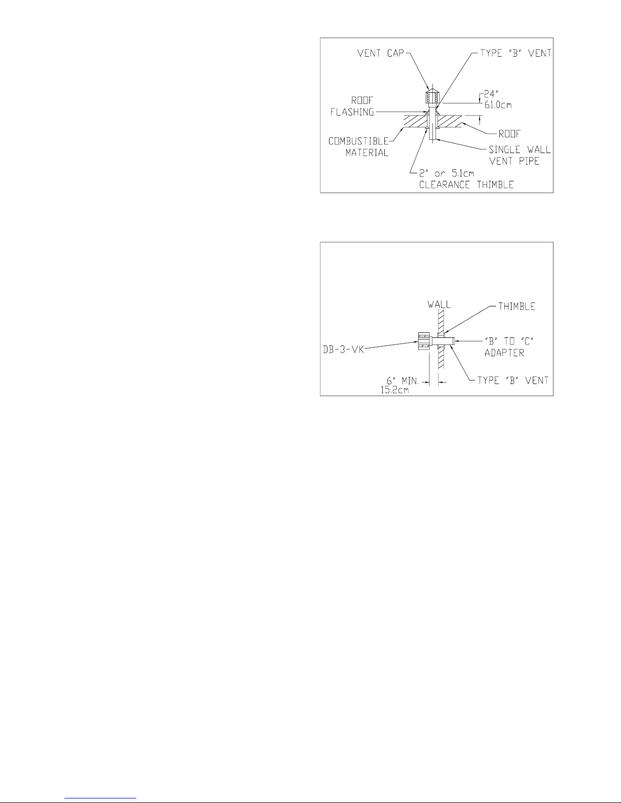
2.8 Flue Venting
The following guidelines must be observed to ensure
proper system performance and safety:
* Check all applicable codes prior to installing flue
stacks. Local codes may vary.
* The heater is designed to operate with a 3-in./7.6cm
diameter 26 ga. minimum exhaust stack.
* Single-wall galvanized flue pipe or Dura/Connect
single wall, flexible connectors must be used. The
portion of the flue pipe which goes through
combustible material in the building wall or roof
must pass through a type “B” vent to maintain
clearance (see figure 2.8.1 through 2.8.2).
* Maximum vent length for all models is 20 ft./6.1m
including two 90 degree elbows.
* The bottom of the vent terminal shall be
located at least 7 ft./2.13m above grade.
* Uninsulated single-wall metal pipe shall not be
used in cold climates for venting gas utilization
equipment.
* The vent terminal of a horizontal venting system
must be installed to prevent blockage by snow and
protect building materials from degradation by
flue gases.
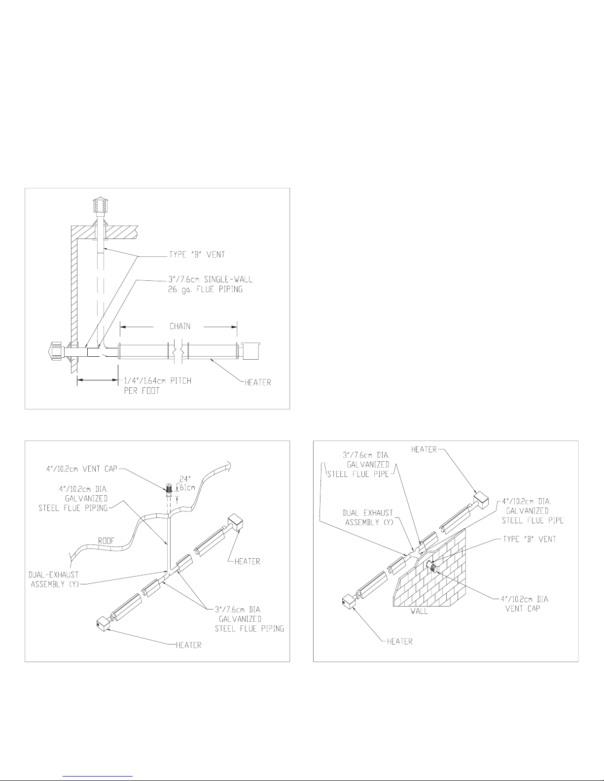
* Vertical venting should be a minimum of 24 inches
/61cm above the roof in an area that prevents snow
blockage. See Figure 2.8.1
* Horizontal venting must maintain a minimum
distance from the vent termination to the sidewall.
See Figure 2.8.2
* Buildings incorporating vented soffits/overhangs
must ensure that the products-of-combustion do
not enter the attic space.
* A common flue of 4 in./10.2cm diameter must be used
for double-venting of units. One thermostat must
control both units. When common venting is
used, flues should be connected so that the byproducts of one heater cannot flow into the
adjoining flue of the other heater. A dual-exhaust
assembly is available from Brant Radiant Heaters,
Part Number DB-3YA (see Figures 2.8.4and 2.8.5). A
Duravent DB-3VK vent kit must be used for sidewall
venting LS models.
Figure 2.8.1
Figure 2.8.2
16
Page 19
* Vertical venting may utilize standard “B” vent
caps.
* All vent pipes must be sealed with high
temperature sealant and 4 No. 8 sheet metal
screws to prevent leakage of flue gas into building.
* Horizontal flues should be pitched down toward
outlet, ¼ in./.64cm per ft. of vent length, to
prevent rain from entering the heater
(see Figure 2.8.3). Do not pitch heater.
Figure 2.8.3
Figure 2.8.4
DUAL-EXHAUST ASSEMBLY
(THROUGH ROOF)
Figure 2.8.5
DUAL-EXHAUST ASSEMBLY
(THROUGH WALL)
17
Page 20
2 INSTALLATION
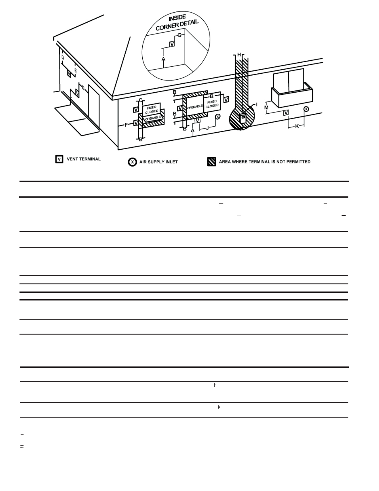
Canadian Installations
A= Clearance above grade, veranda,
porch, deck or balcony
B= Clearance to window or door that may
be opened
C= Clearance to permanently closed
window
D= Vertical clearance to ventilated soffit
located above the terminal within a
horizontal distance of 2 feet (61cm)
from the center line of the terminal
E= Clearance to unventilated soffit
F= Clearance to outside corner
G= Clearance to inside corner
H= Clearance to each side of center line
extended above meter/regulator
assembly
I= Clearance to service regulator vent
outlet
J= Clearance to nonmechanical air supply
inlet to building or the combustion air
inlet for any other appliance
K= Clearance to a mechanical air supply
inlet
L= Clearance above paved sidewalk or
paved driveway located on public
property
M= Clearance under veranda, porch, deck
or balcony
1 In accordance with the current CSA 8149.1 Natural Gas and Propane Installation Code
2 In accordance with the current ANSI Z223.1/NFPA 54, National Fuel Gas Code
A vent shall not terminate directly above a sidewalk or paved driveway that is located between two single family dwellings
and serves both dwellings.
Permitted only if veranda, porch, deck or balcony is fully open on a minimum of two sides beneath the floor
*
a) A minimum clearance value determined by testing in accordance with section 4.7.3, 6.5.5, 8.5.5, or;
b) A reference to the following footnote: “Clearance in accordance with local installation codes and the requirements of the gas
For clearances not specified in ANSI Z223.1/NFPA or CSA B149.1, one of the following shall be indicated:
6 inches(15 cm for appliances < , 10,000
Btuh (3 kW), 12 inches (30cm) for
appliances > 10,000 Btuh (3 kW) and <
100,000 Btuh (30 kW), 36 inches (91cm)
for appliances > 100,000 Btuh (30 kW)
3 feet (91cm) within a height 15 feet
6 inches(15 cm for appliances <, 10,000
Btuh (3 kW), 12 inches (30cm) for
appliances > 10,000 Btuh (3 kW) and <
100,000 Btuh (30 kW), 36 inches (91cm)
for appliances > 100,000 Btuh (30 kW)
supplier.”
12 inches (30 cm)
*
*
*
*
*
(4.5 m) above the meter/regulator
assembly
3 feet (91cm)
6 feet (1.83 m)
7 feet (2.13 m)
12 inches (30 cm)
18
1
6 inches(15 cm for appliances <, 10,000
Btuh (3 kW), 9 inches (23cm) for
appliances > 10,000 Btuh (3 kW) and <
50,000 Btuh (15 kW), 12 inches (30 cm)
for appliances > 50,000 Btuh (15 kW)
US Installations
12 inches (30 cm)
*
*
*
*
*
*
*
6 inches(15 cm for appliances <, 10,000
Btuh (3 kW), 9 inches (23cm) for
appliances > 10,000 Btuh (3 kW) and <
50,000 Btuh (15 kW), 12 inches (30 cm)
for appliances > 50,000 Btuh (15 kW)
3 feet (91 cm) if within 10 feet (3 m)
horizontally
*
*
2
Page 21
2 INSTALLATION
2.9 Installation for Unvented Operation
(OPTIONAL)
NOTE: Not for Residential Applications.
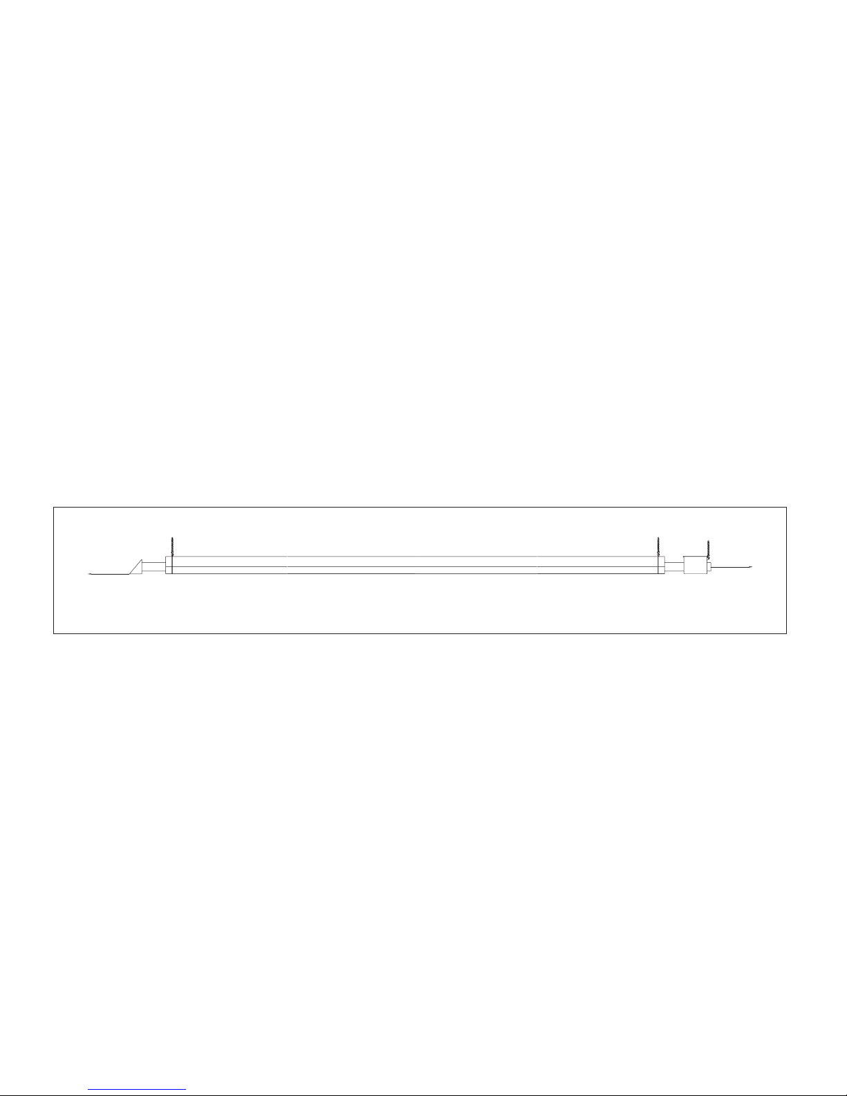
The heaters are approved for unvented operation
when equipped with a factory-supplied end
cap/diffuser. Part No. DB-3VCF (see Figure 2.9.1).
This allows the products of combustion to be
discharged from the units into the space being
heated.
Ventilation of the space is required to dilute those
products of combustion sufficiently. For proper
ventilation, it is recommended that a positive air
displacement of at least 3.8 cfm per 1000 BTUh of
natural gas input be provided.
If propane is used, a positive air displacement of at
least 4.5 cfm per 1000 BTUh of gas input is
recommended. This air displacement may be
accomplished by either gravity or mechanical means.
Provisions must be made for a sufficiently large
fresh-air intake area and exhaust-air outlet area, to
accomplish the displacement. Local codes may require
that the mechanical exhaust system be interlocked with
the electrical supply line to the heaters, enabling both
to function simultaneously.
END
THE MINIMUM END CLEARANCE FOR ALL MODELS IS 12 IN. or 30.5cm
Figure 2.9.1
Figure 2.9.1
END
19
Page 22
2 INSTALLATION
2.10 Combustion Air Requirements
Combustion air intake has a factory-preset air orifice.
If indoor combustion air is to be supplied for a tightly
closed room, one square inch of free air opening
should be provided for each 5000 BTUh of heater
input.
Noncontaminated air for combustion must be ducted
to the heater if chlorinated or fluorinated
contaminants are present in the area where the heater
is installed, or if the building has a negative pressure.
Typical sources of these contaminants are refrigerants,
solvents, adhesives, degreasers, paint removers, paints,
lubricants, pesticides, etc.
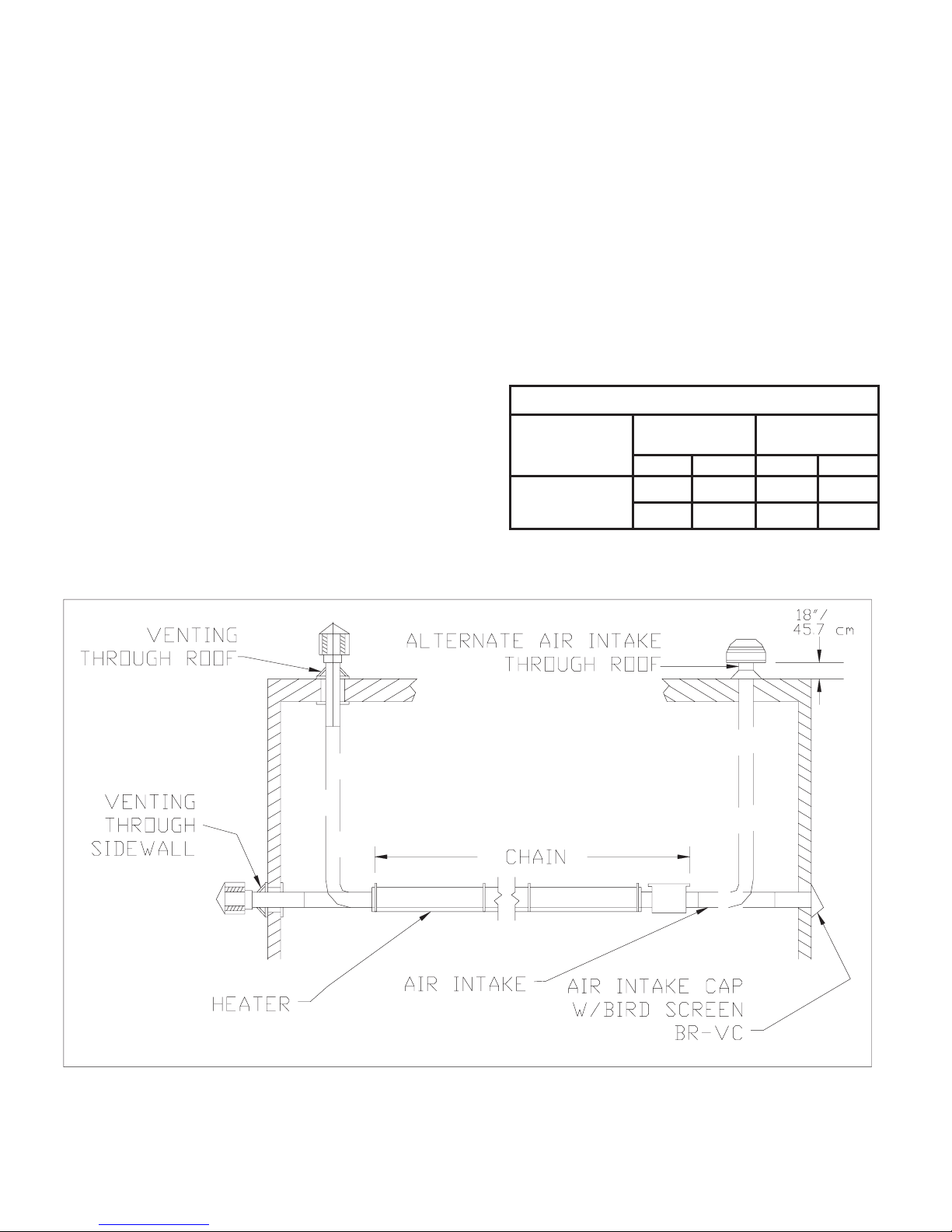
Outside combustion air may be provided by an
accessory 4 in./10.2cm air duct, and directly attached
over the air orifice (see Figure 2.10.1). A BR-VC wall
inlet vent cap must be used with horizontal outside
air intake ducts.
Do not install filters on combustion air.
The intake terminal must be installed to prevent
blockage by snow.
NOTE: Use insulated duct or PVC pipe to prevent
condensation on outer surface. Keep intake opening
at least 3 ft. from any exhaust vent openings. For
limitations of length and size, see Air Duct Chart.
When vertical roof venting the combustion air intake
and exhaust, the exhaust should terminate higher
than the intake.
Two 90 degree elbows are included in duct length.
The air intake terminal must be installed at least one
foot above grade.
AIR INTAKE DUCT CHART
MAXIMUM
INTAKE LENGTH
FT. M
MODEL
ALL
MODELS
AIR INTAKE
DUCT SIZE
IN. CM
4 10.2 35 10.67
5 12.7 50 15.24
Figure 2.10.1
20
Page 23
2 INSTALLATION
2.11 Gas Supply
CORRECT INLET PRESSURES ARE VITAL FOR
EFFICIENT OPERATION OF HEATERS. REFER
TO CSA RATING PLATE AND, IF NECESSARY,
CONSULT GAS COMPANY.
If all or a portion of the gas supply line consists of
used pipe, it must be cleaned and then inspected to
determine its equivalency to new pipe. Test all main
supply lines according to local codes. (Isolate heater
gas valve and gas cock during test.)
Excessive torque on manifold may misalign orifice.
Always use two wrenches when tightening mating
pipe connections.
A typical gas supply line connection is illustrated in
Figure 2.11.1. The method shown will decrease the
possibility of any loose scale or dirt in the supply line
entering the heater’s control system and causing a
malfunction. The gas supply line must be of
sufficient size to provide the required capacity and
inlet pressure to the heater (consult gas company) as
follows:
NOTE: Manifold and inlet pressures should be
checked at the tap on the gas valve. Readings will be
above atmospheric pressure.
* Natural Gas
WARNING
Never use a match or any other flame to test
for gas leaks. Use soap-and-water solution to
check for leaks.
If any portion of the gas supply line is located in an
area that could cause an abnormal amount of
condensate to occur in the pipe, a sediment trap
should be installed.
NOTE: For high-pressure gas above 14 in. W.C.
(Water column), a high-pressure regulator and gas
cock must be use
leaks in the gas supply line, disconnect and cap at
shutoff cock to avoid damage to regulator and gas
valve.
* Gas Line Connection
a. The gas outlet shall be in the same room as the
appliance and the connector must not be
concealed within or run through any wall, floor
or partition.
b. The connector shall be of adequate length.
c. The final assembly shall be tested for leaks.
CAUTION: Matches, candles, open flame or
other sources of ignition shall not be used for
this purpose. Leak test solutions may cause
corrosion - water rinse after test.
d. If compressed air is used to detect
To obtain the required manifold pressure of 3.5 in.
W.C., a minimum inlet pressure of 5.0 in. W.C. is
necessary for purposes of input adjustment. A
maximum inlet pressure of 14.0 in. W.C. is
allowed for all units.
* Propane Gas
To obtain the required manifold pressure of 10.0 in.
W.C., a minimum of 11.0 in. W.C. for purposes
of input adjustment to a maximum of 14.0 in. W.C.
must be provided ahead of the control system on
each heater. Do not exceed a manifold operating
pressure of 10 in. W.C.
Use only a pipe-joint compound that is resistant to
liquified petroleum gases.
* Pressure Equivalents
1 in. W.C. equals 0.58 oz./sq. in.
d. Contact with foreign objects or substances shall
be avoided.
e. The connector shall not be kinked, twisted or
torqued. Refer to page 22.
f. If wind conditions in the space are such that
visible swaying of the heater is apparent, the
control box must be rigidly mounted.
g. Connectors are for use only on piping systems
having fuel gas pressures not in excess of ½
pound per square inch.
21
Page 24
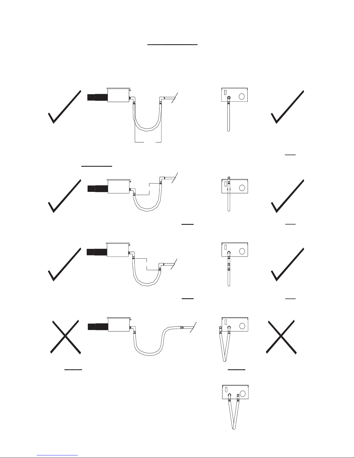
2 INSTALLATION - 1/2" GAS CONNECTION FOR 125,000 btuh OR LESS Figure 2.,11.1
1/2" Gas Connection
Supplied 1/2 inchType I hose is a certified component of the heater and is required on units having inputs
of 125,000 btuh or less. Hoses must be installed in a "U" configuration, as defined in the installation
diagrams, in order to accommodate heater expansion. All measurements are defined when the heater in its
off or cold position.
Gas Supply
7" - 14"
The "U" bend distance required for gas supply connection to heater
18 cm - 36 cm
connection is 7 inches minimum to 14 inches maximum. Hose connections
must be in the vertical position.
Gas Supply
9" (23 cm)
Hose connections must be installed inline
in the same direction as heater expansion.
Gas line supply connection can be installed a maximum of 9 inches above
heater gas connection.
9" (23 cm)
Gas Supply
Gas line supply connection can be installed a maximum of 9 inches below
heater gas connection.
Gas Supply
Hose must not be installed with preload on hose connector fittings.
Hose connections must be installed inline
in the same direction as heater expansion.
Hose connections must be installed inline
in the same direction as heater expansion.
Hose must not be installed with hose connector offset. During operating conditions
a rotational loading of hose may occur.
22
Page 25
2INSTALLATION
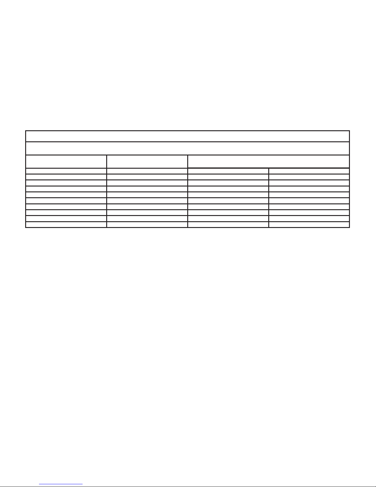
2.12 Allowance for Expansion
Allowances must be made for the system to
expand as detailed in the Heater Expansion Chart
on this page. The supplied
gas connector is recommended. If, however, local
codes require rigid piping to the heater, a swing
joint can be used.
Exchanger length and gas input will determine overall expansion. Heaters in a typical installation will expand towards both the burner and
vent ends. Review for proper flexible gas connector installation.
EXCHANGER LENGTH
FEET / METERS
10
10
10
15
15
15
15
20
20
30
3.1
3.1
3.1
4.6
4.6
4.6
4.6
6.1
6.1
9.2
Type I, flexible
FIXED OR HIGH-FIRE
GAS INPUT BTUh
25,000
30,000
40,000
25,000
30,000
40,000
50,000
40,000
50,000
50,000
HEATER EXPANSION CHART
INCHES MILLIMETERS
1/2
5/8
¾
5/8
¾
7/8
1
1
1¼
1¼
EXPANSION LENGTH
12.7
15.9
19.1
15.9
19.1
22.2
25.4
25.4
31.8
31.8
3
2
Page 26
2 INSTALLATION
Electrical Requirements
2.13
1. Heaters operate on 120 volts, 60 Hz, single
phase. The maximum amperage requirement
(starting current) is 4.8 amps per heater. The
running current is 1.1 amps.
2. Heater must be grounded in accordance with the
Canadian Electrical Code C22.1 (latest edition).
3. Wiring must not be exposed to direct radiant
output.
2.14
Lighting Instructions
1. Purge main gas supply line at start-up.
2. Rotate heater’s manual gas valve knob to the
“ON” position.
3. Close electrical circuit.
4. If heater fails to light, turn off gas and wait five
minutes before repeating the above procedure.
4. Observe proper electrical polarity.
5. It is recommended that the thermostat be
installed on the hot side of a fused supply
line and have sufficient ampere rating for
the heater(s) it controls.
Instructions pour l’allumage
1. Purger la conduite d’alimentation en gaz
principale.
2. Tourner le bouton du robinet de gaz a commande
manuelle jusqu’a ce qu’il se trouve en position de
marche (”ON”).
3. Fermer le circuit electrique.
4. Si l’appareil de chauffage ne s’allume pas,
attendre 5 minutes avant de suivre de nouveau les
instructions ci-dessus.
Shutdown Instructions
2.15
1. Open electrical circuit.
2. Rotate heater’s manual gas valve knob to the
“OFF” position.
This appliance does not have a pilot. It is equipped with an ignition device which automatically lights
the burner. Do try to light the burner by hand. Use only your hand to turn the manual shutoff.
Never use tools. Turn shutoff clockwise to “ ”. Turn shutoff counterclockwise to “ ”. If the
knob will not turn by hand, do not try to repair it, call a qualified technician. Force or attempted
repair may result in a fire or explosion.
NOT
Pour eteindre l’appareil
1. Ouvrir le circuit electrique.
2. Tourner le bouton du robinet de gaz a commande
manuelle de l’appareil de chauffage jusqu’a ce
qu’il se trouve en position d’arret (”OFF”).
IMPORTANT
OFF ON
4
2
Page 27

2 INSTALLATION
Outdoor Installations
2.16
The LS Series heaters have been certified for
outdoors installations with the following factory
requirements.
* BR-VC to be attached to the 4 in. combustion air
intake collar pointing downward to prevent rain
from entering the intake. Factory supplied.
* Water and UV resistant cord and plug factory
installed through a liquid-tight box connector.
* Control box will be internally silicone sealed.
* All manufactured Re-Verber-Ray outdoor approved
heaters will display “FOR OUTDOOR USE” on the
rating label.
When installing heaters in outdoor applications the
following considerations must be met:
* Locate heater away from snow load areas.
* Heaters mounted lower than 8 ft./ 2.4 m must use
an optional protective grill (BR-PS60).
* Heaters must not be mounted lower than 7 ft./ 2.1 m
above finished grade.
* Ensure that the products-of-combustion dissipate
without condensing on buildings surfaces.
5
2
Page 28
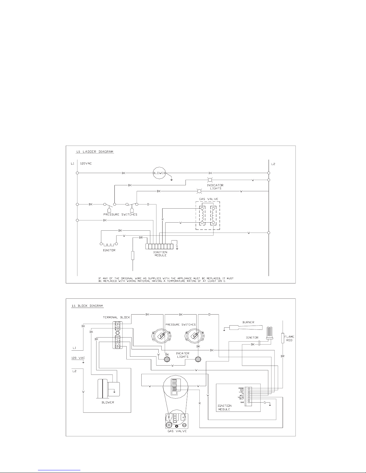
3 THEORY OF OPERATION
3.1 LS Models
STARTING CIRCUIT (FIGURES 3.1.1 & 3.1.2)
When voltage is applied to L1 and L2, a circuit is
completed from L1 via the blower motor to L2. The
blower fan is mounted in the control box and rated
to supply sufficient air for combustion.
Air pressure generated by the blower will cause the
normally open burner pressure switch No.1 to close.
Another circuit is completed from L1 to the hot
surface ignition control and back to L2. There is a
five-second delay, then the glo-bar is powered. After
the glo-bar has been powered for 45 seconds, the
control causes the gas valve to open and initiates the
Ignition trial. Power to the glo-bar is shut off during
the last two or three seconds of ignition trial.
RUNNING CIRCUIT
After ignition the flame rod monitors the main burner
flame. As long as a flame is present, the valve is held
open. If the flame is lost, the control acts to close the
valve within one second, and a new trial sequence
identical to that at start-up is initiated. If proof of flame
is not established within 8.5 seconds, the unit will lock
out. If lockout occurs, the control can be reset by briefly
interrupting the power source.
Figure 3.1.1
Figure 3.1.2
26
Page 29
4 SERVICE
4.1 Maintenance
LS Series gas-fired infra-red heaters require
minimum of routine maintenance to keep them
operating at peak performance.
1. Ensure that the heaters air inlet and blower
impeller is kept clean. If dirt becomes a problem,
installation of outside air intake duct for
combustion is recommended. Oiling the blower
motor will extend bearing life beyond the 30,000
hour minimum.
2. Combustion air inlets, grills or louvres must be
inspected regularly to ensure that they are clear
and free of dust, snow, ice, frost and other foreign
material so that air may freely enter.
3. Ensure that all intake air ducts are sealed.
4.2 Access Panels
Turn gas supply off and disconnect electrical source
before attempting to service.
4. Heaters exhaust vent must be inspected
periodically to ensure it is free and clear of
foreign material.
5. Unvented heaters utilizing DB-3VCF vent cap
with flapper must ensure that the flapper moves
freely without obstructions.
6. Keep the aluminum reflectors from accumulating
deposited material. Vacuum or blow all dust and
debris off the heater.
WARNING
Use protective glasses when cleaning
the heater.
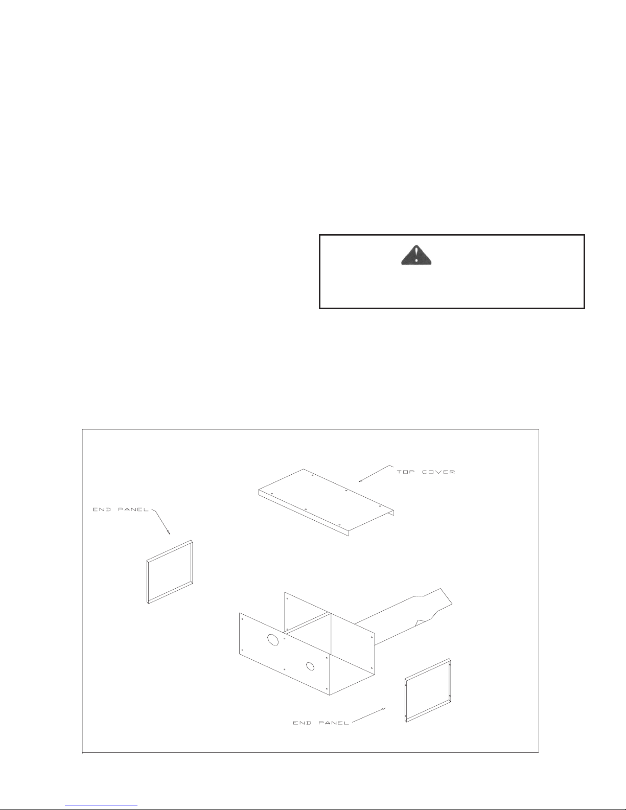
Service access panels may be removed as required.
(see Figure 4.2.1)
Figure 4.2.1
27
Page 30

4.3 Thermal Limit Switch
The therm
al limit switch is a safety device designed
to discontinue heater operation if the control box
temperature exceeds its operational limit.
The failure of a thermal limit switch indicates a
problem within the heater, or its venting systems.
Problem areas must be located and rectified before a
safe operating condition exists. Listed below are
possible causes and corrective action.
Possible Cause
1. Restricted outside air duct.
2. Restricted air inlet orifice.
3. Dirty fan blower wheel.
4. Faulty pressure switches.
5. Restricted vent.
6. Restriction in radiant pipes.
7. Gas leak in valve train.
8. Negative pressure in building.
CAUTION
To test: DISCONNECT ELECTRICAL POWER
SUPPLY and check switch for continuity. If the
Therm
al limit switch circuit is “open”, remove and
replace.
Corrective Action
Clean
Clean
Clean
Replace
Clean
Clean
Repair or replace
Install outside air duct
Customer service toll free #1-800-387-4778
28
Page 31

4.4 Service
* Do not use this appliance if any part has been
under water. Immediately call a qualified service
technician to inspect the appliance and to replace
any part of the control system and any gas control
which has been under water.
* CAUTION: Label all wires prior to disconnection
when servicing controls. Wiring errors can cause
improper and dangerous operation.
* Verify proper operation after servicing.
* WARNING: Failure to position the parts in
accordance with these diagrams or failure to use
only parts specifically approved with this
appliance may result in property damage or
personal injury.
* Ne pas se servir de cet appareil s’il a été plongé
dans l’eau, complètement ou en partie. Faire
inspecter l’appareil par un technicien qualifié et
remplacer toute partie du système de contrôle et
toute commande qui ont été plongées dans l’eau.
* ATTENTION: Au moment de l’entretien des
commandes, étiquetez tous les fils avant le
débranchement. Des erreursde câblage peuvant
entraîner un fonctionnement inadéquat et
dangereux.
* S’assurer que l’appareil fonctionneadéquatement
une fois l’entretien terminé.
* AVERTISSEMENT: Risque de dommages ou de
blessures si les pièces ne sont pas installées
conformément à ces schémas et ou si des pièces
autres que celles spécifiquement aprouvées avec
cet appareil sont utilisées.
2
9
Page 32
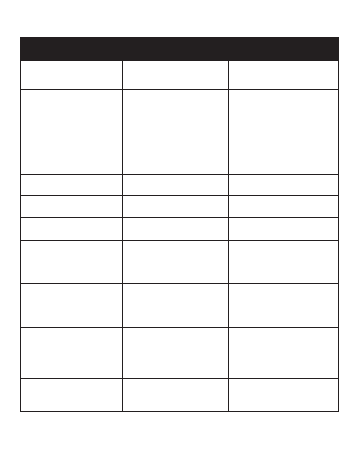
4.2 GENERAL TROUBLE SHOOTING
SYMPTOM POSSIBLE CAUSE CORRECTIVE ACTION
Thermostat closed.
-NOFAN
Fan Operates
- NO INDICATOR LIGHTS
- NO HEATER OPERATION
Fan Operates
Burner Switch Light Operates
- NO EXHAUST SWITCH LIGHT
- NO HEATER OPERATION
Fan Operates
Indicator Lights Operates
- NO GLOBAR
Indicator Lights Operate
Glo-Bar Operates
- NO GAS VALVE
Glo-Bar Operates
Gas Valve Operates
- NO IGNITION
Gas Valve Operates
Ignition Occurs
- HEATER CYCLES OFF
- GOES INTO LOCKOUT
Heater Operating
- TUBE BOWING
1. Blown fuse.
2. Faulty thermostat.
3. Disconnected wire.
4. Faulty fan.
1. Blocked air intake.
2. Burner switch wire disconnected.
3. Burner switch faulty.
4. Burner switch sensing tubes plugged.
5. Control box lid loose or leaking.
1. Exhaust vent blocked.
2. Exhaust switch wire disconnected.
3. Exhaust switch faulty.
4. Excessive wind pressure on vent cap.
5. Wrong baffle installed.
1. Glo-bar broken.
2. Circuit board faulty.
3. Wiring harness disconnected.
1. Circuit board faulty.
2. Gas valve faulty.
3. Wire disconnected.
1. Blocked gas orifice.
2. Low gas pressure.
3. Low glo-bar surface temperature.
1. Flame sensor faulty.
2. Heater not grounded.
3. Electrical supply service panel not grounded.
4. Gas valve faulty.
5. Circuit board faulty.
6. Electrical polarity incorrect.
1. Insufficient combustion air.
2. Overfired.
3. Ensure exchangers have room to expand.
4. Heater not supported properly.
5. Reflectors not positioned properly.
6. Baffle installed wrong.
1. Replace.
2. Replace.
3. Repair.
4. Replace.
1. Remove all foreign matter in intake air stream.
2. Repair.
3. Replace.
4. Remove clean and install.
5. Secure or reseal.
1. Remove all foreign matter in vent.
2.Repair.
3. Replace.
4. Verify cap, extend or relocate.
(See Flue Venting 2.8)
5. Consult tube assembly baffle chart for
proper lengths. (See page 14)
1. Replace.
2. Replace.
3. Reconnect or replace.
1. Replace.
2. Replace.
3. Reconnect.
1. Remove & clean.
2. Provide required gas pressure.
3. Replace-ensure a clean air supply.
1. Replace.
2. Locate and repair.
3. Locate and repair.
4. Replace.
5. Replace.
6. Reconnect
1. Check intake duct for blockage and sizing.
2. Check gas pressure.
3. Re-install vent connection.
4. Re-position hangers or chains.
5. Re-position.
6. Re-position.
.
Heater Operating
- VENT CONDENSING
Odor or fumes in space.
1. Stack length too long.
2. Light gauge flue pipe used.
3. Uninsulated vent pipe running
through cold space.
4. Negative pressure in building.
5. Common vented heaters installed
with individual thermostats.
1. Vaporized solvents decomposing
when contacting radiant tubes.
2. Lift trucks.
3. Loose tube connections.
30
1. Shorten stack.
2. Minimum 26 Ga. Required.
3. Insulate vent.
4. Install combustion air intake.
5. Install one thermostat.
1. Install exhaust fan at ceiling.
2. Install exhaust fan and repair.
3. Tighten to 50-60 lb.-ft.
Page 33

LIMITED
Three Year Warranty
RE-VERBER-RAY TUBE TYPE GAS INFRA-RED HEATER
Brant Radiant Heaters Limited (hereinafter
referred to as the Company) warrants to the
original purchaser or original user that all Brant
Radiant Heaters sold by it and all parts thereof
are free from defects in material and/or
workmanship under a normal use and service.
The Company’s sole obligation under this
warranty shall be limited to furnishing
replacement parts, F.O.B. Paris, Ontario, for 12
months from the date of initial installation of the
heater, but not to exceed 12 months from the
date of shipment by the Company to original
purchaser for the heater, for any parts which the
Company’s examination shall disclose to its
satisfaction to be defective. Defective parts to be
returned to the Company, transportation charges
prepaid.
ONE YEAR ADDITIONAL
WARRANTY ON
COMBUSTION CHAMBER/
RADIANT TUBE
In addition to the above mentioned OneYear Warranty, the Company warrants to the
original purchaser or original user of TUBE
TYPE Gas Infra-Red Heater that it will at any
time during the two years next following the
expiration date of the One-Year Warranty,
furnish combustion chamber / radiant tube
F.O.B. Paris, Ontario, for any combustion
chamber / radiant tube which is proved to the
satisfaction of the Company to be inoperative
due to defects in material or factory
workmanship. The Company’s sole obligation
under the warranty shall be limited to furnishing
combustion chamber radiant tube.
This one-year additional warranty covers
the combustion chamber / radiant tube only.
TWO YEAR ADDITIONAL
WARRANTY ON
RADIANT TUBE
In addition to the above mentioned Two-Year
Warranty, the Company warrants to the original
purchaser or original user of TUBE TYPE Gas
Infra-Red Heater that it will at anytime during the
two years next following the expiration date of the
One-Year Warranty, furnish radiant tube F.O.B.
Paris, Ontario, for any radiant tube which is proved
to the satisfaction of the Company to be inoperative
due to defects in material or factory workmanship.
The Company’s sole obligation under the warranty
shall be limited to furnishing radiant tube.
This two-year additional warranty covers the
radiant tube only.
GENERAL CONDITIONS
The warranties set out in this certificate are
the exclusive remedy of the original owner or
user in lieu of all other warranties written, oral
and / or implied (including any warranty of
merchantability or fitness for the purpose) and
all other obligations and / or liabilities on the
part of the Company, and the Company neither
assumes nor authorizes any person to assume for
it any other obligation or liability in connection
with the sale, installation or use of the heater or
any parts thereof.
The company will not be responsible for
labour charges for the analysis of a defective
condition in the heater and / or for the
installation of replacement parts.
The warranties provided herein will not
apply if the input of the heater exceeds the rated
input, as indicated on the name plate, by more
than 2%, or if the heater in the judgement of the
Company has been subjected to misuse,
excessive dust, negligence, accident, corrosive
atmospheres, excessive thermal shock,
excessive vibration, physical damage to the
heater, alterations by unauthorized service,
operation contrary to the Company’s
instructions or if the serial number has been
altered, defaced or removed. The Company shall
not be liable for any default and / or delay in the
performance by it of these warranties caused by
contingency beyond its control, including war,
government restriction or restraints, strikes, fire,
flood, Acts of God, short or reduced supply of
raw materials, or parts.
The warranties herein shall be null and void
if the heater is not installed by a competent
heating contractor and / or if the heater is not
installed according to Company instructions and
/ or if the heater is not maintained and repaired
according to Company instructions.
Written permission is required for the
return of any part and / or equipment and any
such return must be made on the basis of
transportation charges prepaid. Shipments may
be refused unless prior written permission is
obtained and goods returned prepaid.
This warranty applies only within Canada.
Page 34

Manifold (HL-MFD)
Flame Rod Wire
Description
TP-78DU Circuit Control
TP-224
TP-223
Part No.
TP-78DUH Harness
the model and serial number of the heater.
NOTE: When ordering heater parts, please state
Description
Exhaust Vent w/Flapper 3”
.
DB-3VCF
Item No
5.2 Optional Parts
RH-1/2)
Side Wall Venting Kit
Wall Inlet Vent w/Screen
(Required on Unvented Models)
DB-3-VK
BR-VC
90° bend X 3” dia. tube kit
180° bend X 3” dia. tube kit
Radiant Tube Protective Screen 60”
Side Shield Extension
DB-3UA
BR-PS60
BR-NIR
Gas Cock
TP-33B
DB3EA
Heat Diffuser (Baffle)(state model)
#8 x ½ in. Machine Screw
Burner Pressure Switch (state model)
Description
DB-65
TP-62
TP-61K
Part No.
Control Box
#8 x 1/4” Sheet Metal Screw
Control Box Cover
Description
Liquid Tight Connector (TP-LTC)
Cord & Plug (DB-CP)
TP-67
TP-66
1/4-20 x ½” Machine Screw
Flange Gasket
Rubber Grommet
Control Box Cover Gasket
Strain Relief Bushing
TP-76
TP-70
TP-68A
Conduit ½” x 4”
Conduit Coupling
1/4-20 Hex Nut
#6-32 Hex Nut
#6-32 x 1 in. Machine Screw
TP-81
TP-80
Glo-Bar Box Cover
Glo-Bar Box
Reflector Clip (BR-ECRC)
Reflector End Cap (BR-ECR)
Flexible Gas Connector (SS-24)
Type I
TP-106
TP-105
TP-83
Sight Glass Gasket
#8 x 1/2” Self-Drilling Screw
Thermal Limit Switch
DB-114
Sight Glass Washer
Sight Glass
16 in. Burner Tube (AL-TI (LS-16P)
Burner (HD-201P)
Air Inlet Gasket
TP-202
TP-201
TP-122
Tube/Reflector Hanger (DB-3HGR)
1/4-20 x 3/8” Thread-Cutting Screw
Gas Orifice (TP-46)(state model)
TP-204
Refector (120”)
Reflector Center Support (DB-3IH)
End Panel-left
Glo-bar Holder
TP-206
TP-205
10 ft. Radiant Tube, Straight 3”
Tube Clamp 3”
(state N.G. or L.P.)(TP-75)
Gas Valve
“Z” Bracket
End Panel-right
TP-210
TP-208
TP-207
1/4-20 Keps Nut
Control Box Bracket
10 ft. Radiant Tube, Straight 3” (AL-TI)
Indicator lights (TP-IL)
3 in. X ½ in. Pipe Nipple
TP-216
TP-212
Burner Box Divider
Globar Ignitor
Inlet Air Orifice w/Screen
Exhaust Pressure Tube (High Temp.)
Pressure Barb Fitting
TP-218
TP-217
Fan Blower (25,000 & 30, 000)
Fan Blower (40,000 & 50,000 BTU)
Flame Rod (BR-FR)
Glo-bar Gasket
TP-222
TP-219
¼ in. Pressure Tube
¼ in. Atmosphere Tube (Vinyl)
Exhaust Pressure Switch (state model)
#8 Hex Nut/Lock Washer
5.1 BASIC PARTS LIST
Part No.
TP-11
TP-10
TP-9
TP-7A
TP-7
TP-5
TP-4
TP 3
TP-1
TP-12
TP-13
TP-14
TP-15
TP-16
TP-17
DB-19C
DB-19B
TP-20
DB-26
TP-21G
DB
TP-31B
DB-26T
TP-41
TP-44
TP-50
TP-54
DB-109
TP-55/N
TP-57A
TP-56C
TP-59
TP-60K
Page 35
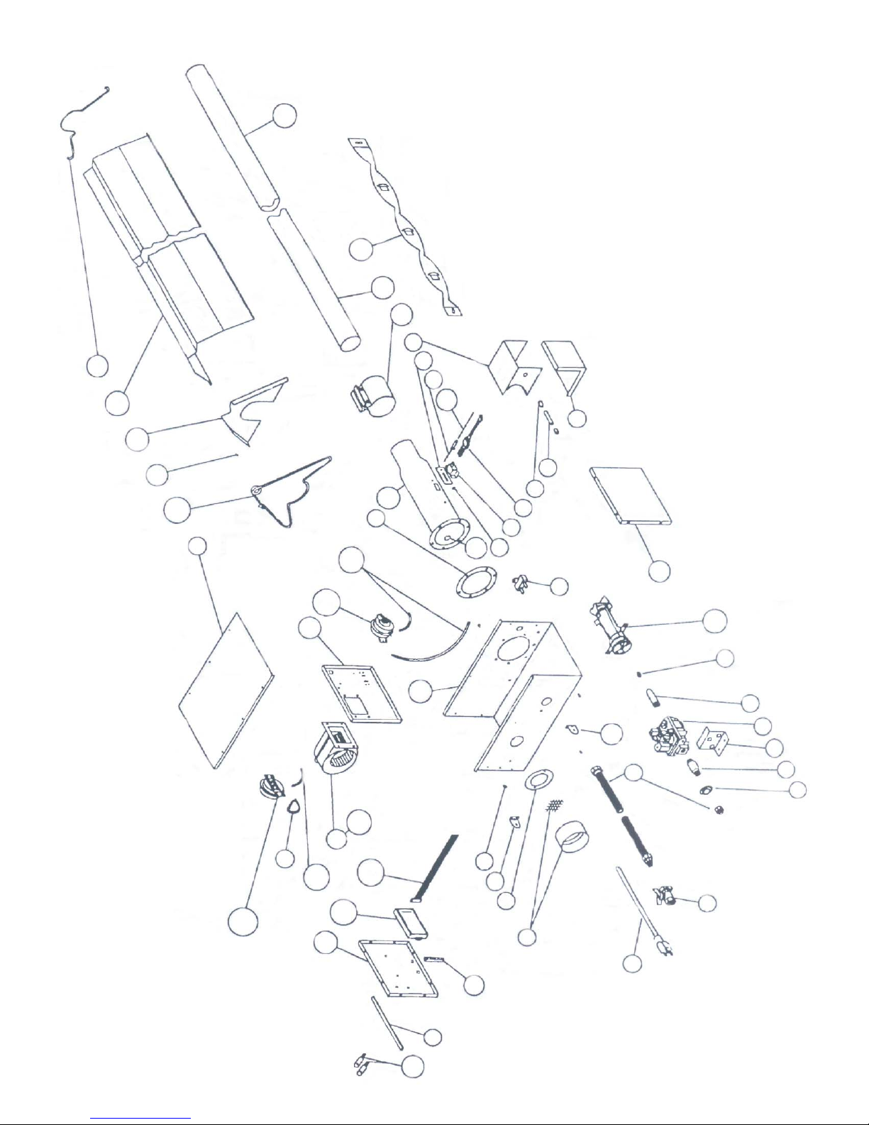
19C
26
65
26T
21G
11
221
222
20
105
223
12
106
19B
10
9
202
5
1
218
60K
54
4
109
55
57A
56C
61K
206
78DUH
78DU
16
329
68A
217
31B
122
205
50
207
114
201
204
224
31B
83
33B
44
66
210
208
212
76
70
216
Page 36

 Loading...