

Page 1
Branick Industries, Inc. • 4245 Main Avenue • Fargo, North Dakota 58103
REV060316 P/N: 81-0199D
Installation, Operation
& Repair Parts
Information
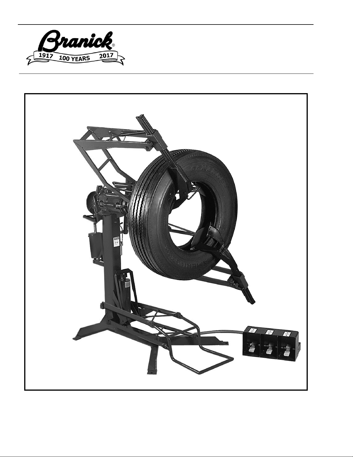
MODEL EF/HD
Full Circle
Tire Spreader
Page 2

1
TABLE OF CONTENTS _______________________________________________________
SAFETY INSTRUCTIONS 1
DEFINITIONS 1
INSTALLATION INSTRUCTIONS 2
OPERATING INSTRUCTIONS 2,3
MAINTENANCE 3
REPAIR PARTS 4-14
REPAIR PARTS LIST 9-14
WARRANTY 15
SAFETY INSTRUCTIONS _____________________________________________________
▪ NEVER allow unauthorized personnel to operate this product.
▪ NEVER use this product for anything other than its intended use.
▪ THOROUGHLY train new employees in the proper use and care of this product.
▪ PROHIBIT unauthorized personnel from being in shop area while this product is in use.
DEFINITIONS _______________________________________________________________
▪ CAUTION: Indicates a potentially hazardous situation, which if not avoided, may result in damage to
property or minor personal injury.
▪ HAZARD: A source of potential injury to a person.
▪ MAINTENANCE: Those actions that preserve the correct and proper conditions under which the machine
shall be used. This may include adjustment, replacement of wear items, lubrication and cleaning, but not
modifications or repair of damage.
▪ MAY: This word is understood to be permissive.
▪ MUST: This word is understood to be mandatory.
▪ OPERATION: The correct and proper use of the machine as described in this manual.
▪ SAFETY ALERT SYMBOL: A symbol that indicates a potential personal safety hazard. It is composed of
an equilateral triangle surrounding an exclamation point.
▪ SHALL: This word is understood to be mandatory.
▪ SHOULD: This word is understood to be advisory.
▪ WARNING: Indicates a potentially hazardous situation, which if not avoided, may result in death or
serious personal injury.
Page 3
2
INSTALLATION_____________________________________________________________
1) Position the Model eF/HD on a solid level floor leaving a minimum of 12 inches of clearance from rear and 24
inches of clearance from sides. The eF can be bolted down if desired using the four holes in bottom of frame.
2) Attach the loose spread arm spring to spread arm. Refer to the other spread arm for proper spring location.
3) Attach the lift cradle to the lower lift arms.
5) Install a 1/4 NPT quick coupler nipple (not provided) into the air filter located on frame column. Use 1/4 inch air
hose with 100 p.s.i. minimum.
OPERATION________________________________________________________________
1) Roll tire onto lift cradle, and while balancing the tire with hands, step on left foot valve to raise tire just above
inner bead hooks. Release lift valve to allow cradle to lower to floor and tire hanging on inner bead hooks.
2) While keeping tire on inner bead hooks, step on center foot valve to spread and fully engage all four hooks on
inner bead of tire.
3) Grasp both outer bead hook arms by the handles and pull to center of tire. Push forward and allow bead
hooks to engage outer bead of tire. Make certain all hooks are securely engaged with tire beads before
spreading tire.
4) To spread the tire, step on right foot valve to obtain desired spread. Tire can now be rotated and inspected.
CAUTION
Before using this product, read and fully understand the operating
instructions and all decals on the product. This is necessary to
prevent injury to the operator and damage to the product.
This product is intended to be used to spread tire casings for
inspection and/or repair only.
Keep fingers and hands clear of all hooks and mechanisms during
operation.
Do not use this product if it is visibly worn, distorted or damaged.
Always wear appropriate eye protection.
WARNING
Keep feet clear of the tire lift when raising and lowering tire.
All personnel must be clear of the spread arms during operation.
Page 4
3
5) To remove tire, release spread arm control valve (right valve) and remove outer bead hook.
6) Release pressure on inner bead hooks by stepping on diameter control valve (center valve).
7) With tire hanging on inner hooks, raise lift cradle (left valve) up to contact tire. While holding onto tire, raise
tire slightly above inner bead hooks and lean tire outward and release pressure on lift valve to lower tire to
floor.
MAINTENANCE_____________________________________________________________
MONTHLY – Put a few ounces of 10 or 20 weight oil in all cylinders.
Lubricate all moving parts (bolts, hinges, rollers, etc.) with a lubricating oil.
Grease cylinder bearings through the grease zerk fittings.
Apply some grease to the races of the bearings also.
WARNING
Do not release the inner bead hooks (center valve) until the outer
bead hooks have been released (right valve) and removed from tire.
Page 5
4
REPAIR PARTS _____________________________________________________________
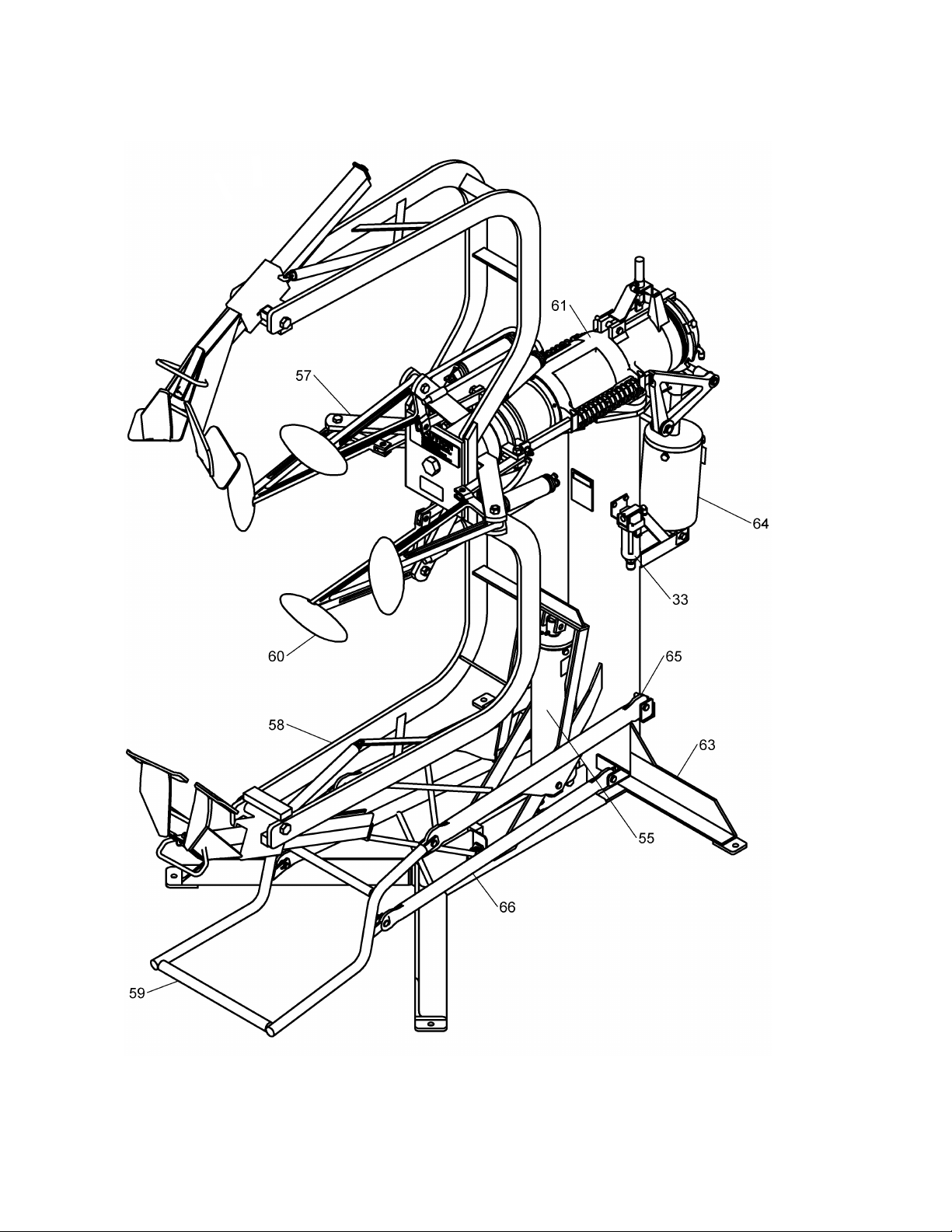
Model HD.EF General Assembly
See parts list on page 9 & 10
Page 6
5
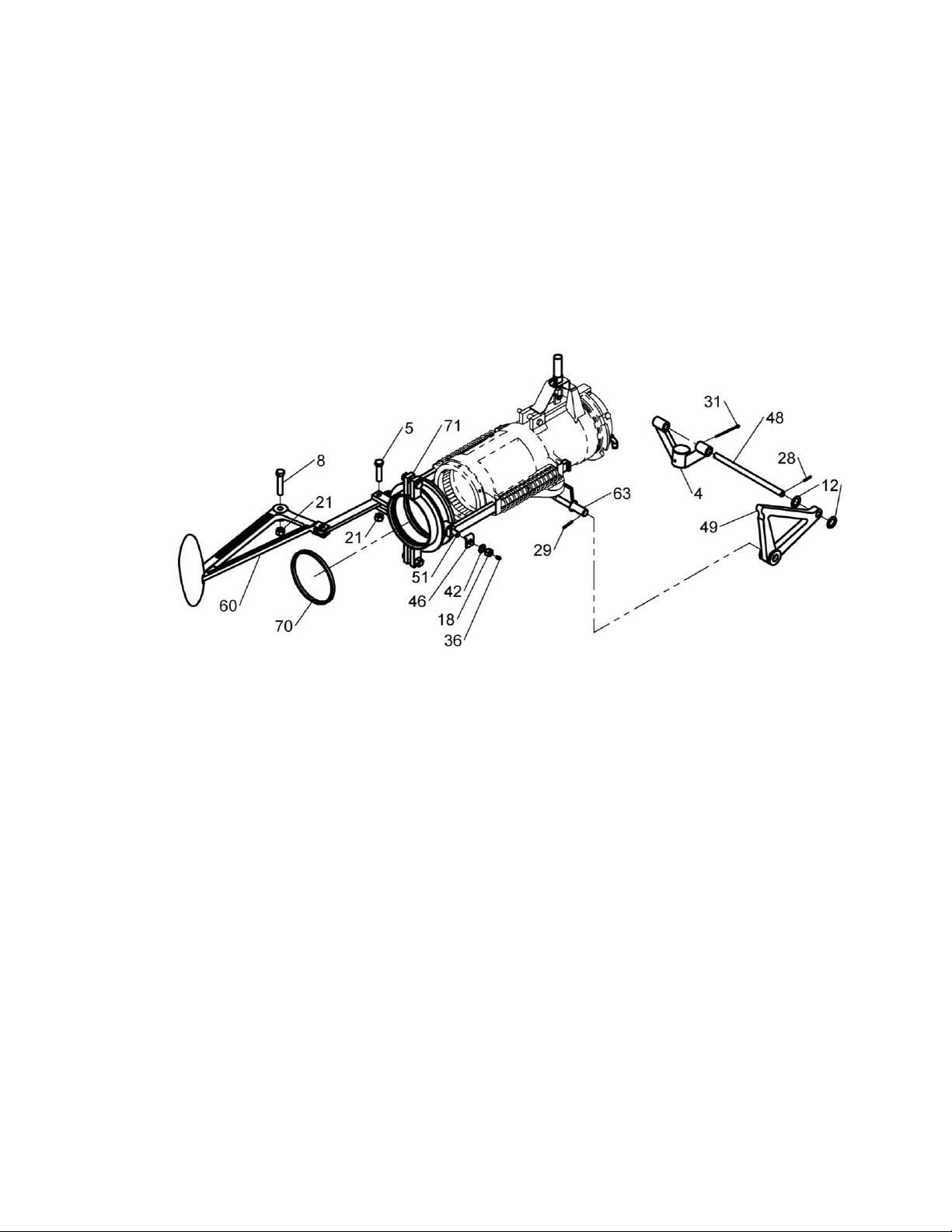
Diameter Arms & Linkage
See parts list on page 9 & 10
Page 7
6
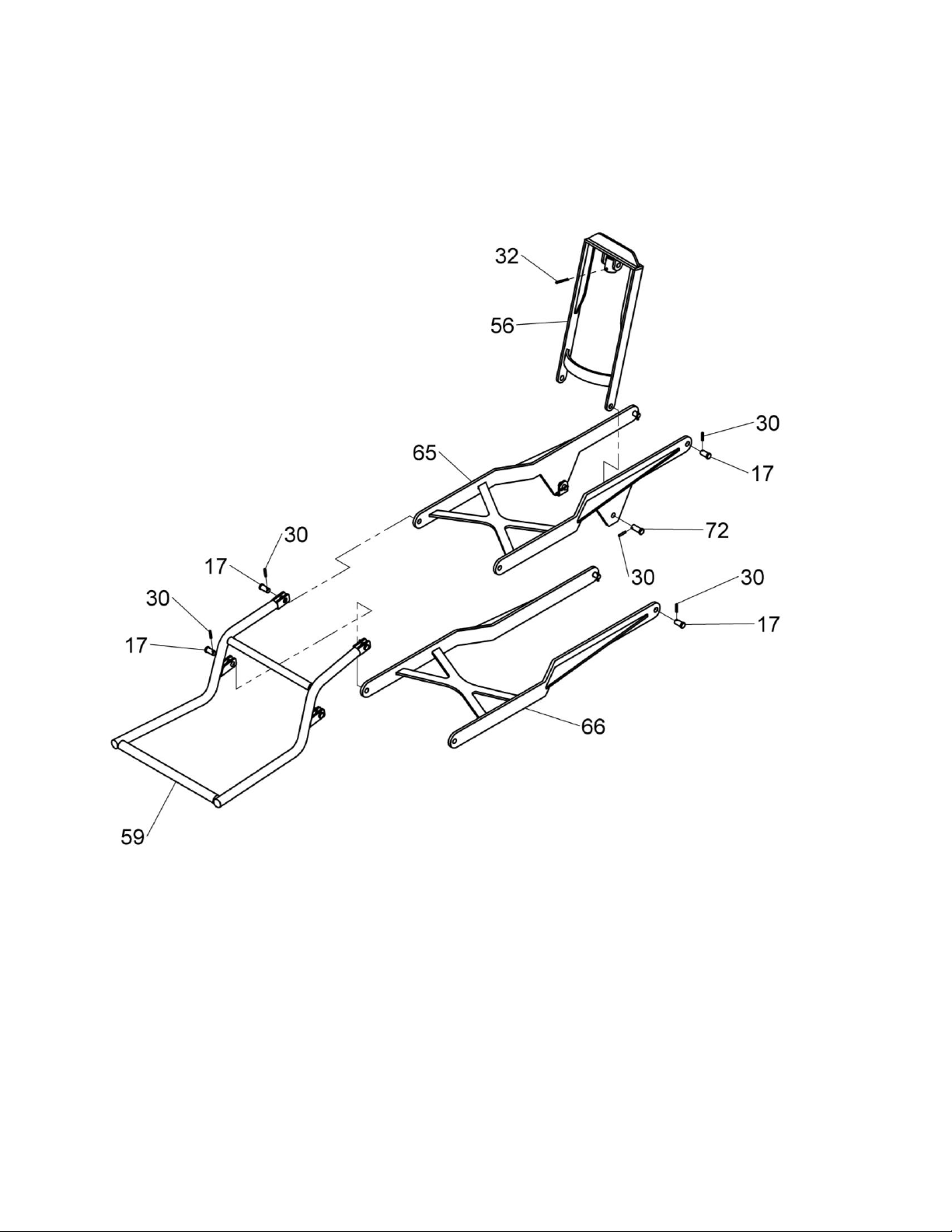
Lift Cradle Assembly
See parts list on page 9 & 10
Page 8
7
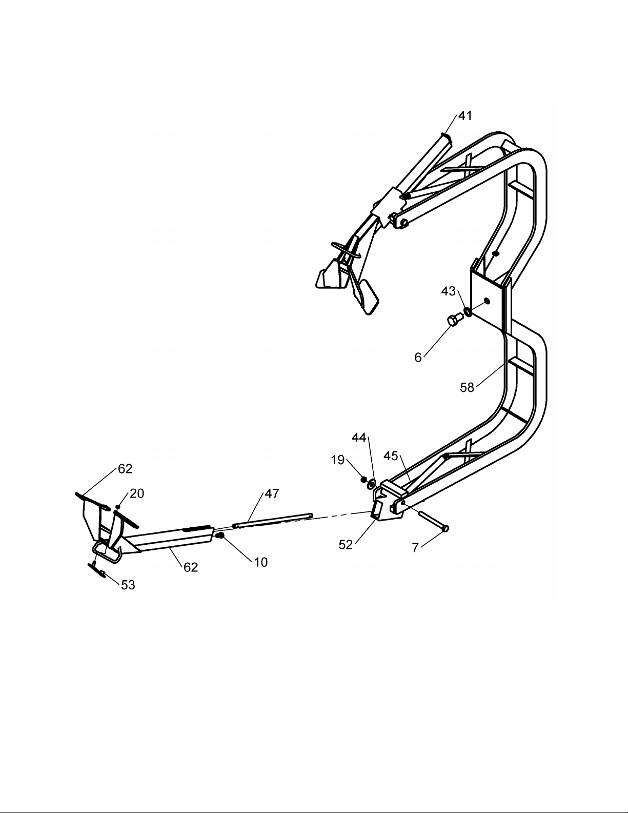
Spread Arms Assembly
See parts list on page 9 & 10
Page 9
8
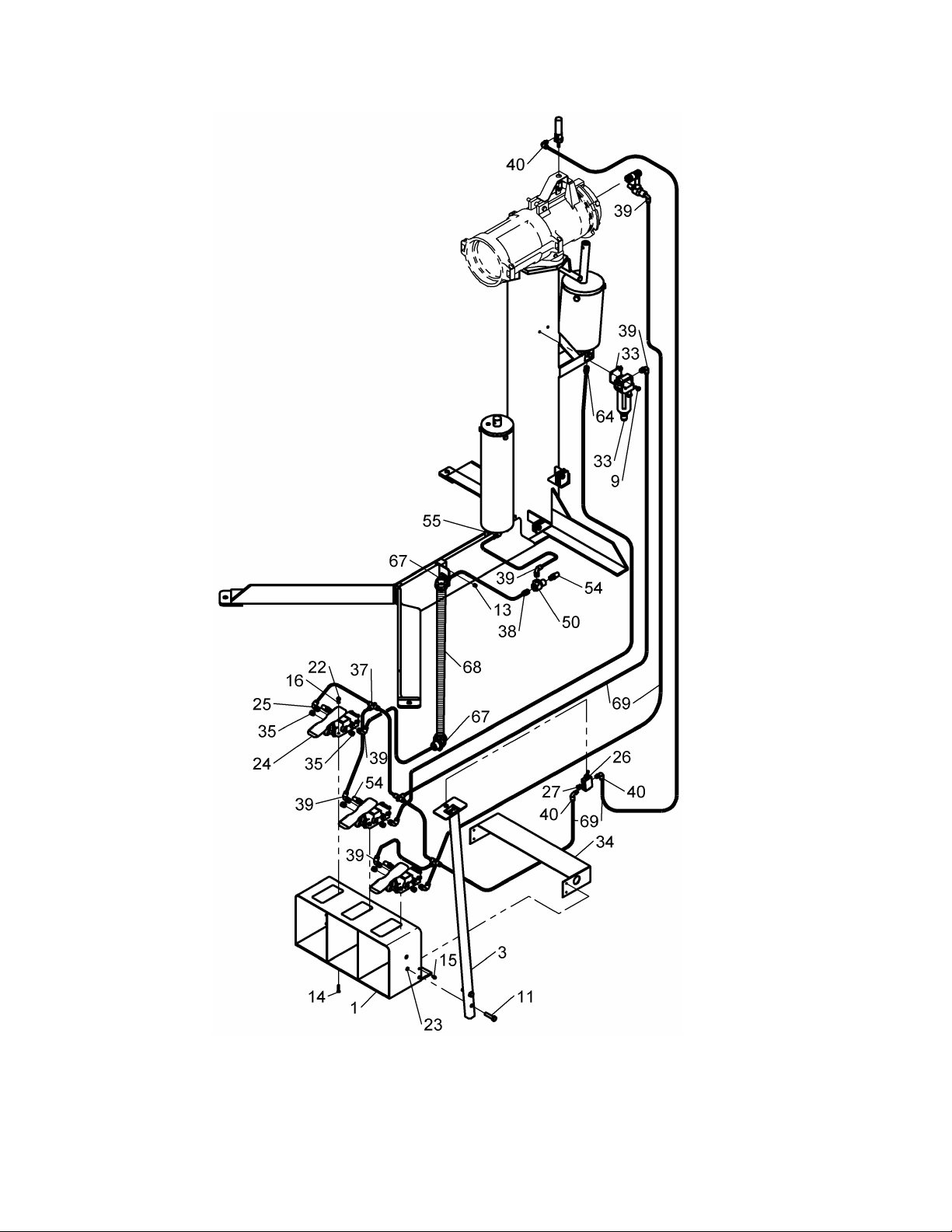
Pneumatics
See parts list on page 9 & 10
Page 10
9
REPAIR PARTS LIST ________________________________________________________
ITEM
QTY
PART NO.
DESCRIPTION
1 1 03-0048
WELD, FOOT GUARD
2 1 03-0052
WELD, FITTING MOUNT
3 1 03-0219
WELD, VALVE MOUNT
4 1 03-0363
CONNECTOR, HDEF DIA. CYL.
5 6 028-006
SCREW, 1/2 X 2 NC H.H.C
6 1 028-017
SCREW, 1 X 1 3/4 N.C H.H.C
7 2 028-024
SCREW, 5/8 X 6 N.C H.H.C
8 4 028-089
SCREW, 1/2NC X 2 1/2 HHC
9 2 028-132
SCREW, 1/4-20 x 1/2 HHC
10 2 028-159
SCREW, 1/2-13 X 1 HHC
11 2 028-289
SCREW, 3/8-16 X 1 1/2 HHC
12 4 039-002
BUSHING, 3/4 MACHINE
13 1 50-0006
SCREW, 5/16-18 SS
14
12
50-0041
SCREW, #8-32 X 1 CSK HD MACH
15 4 50-0090
SCREW, #8-32 X 3/8 SHH TAPPING
16
12
52-0006
WASHER, #8 INT TOOTH LOCK
17 8 54-0003
PIN, 1/2 x 1 CLEVIS
18 2 055-010
NUT, 1/2-20 HEX JAM
19 2 055-011
NUT, 5/8 HEX
20 2 055-023
NUT, 5/16-18 PREV TORQ LOCK
21
10
055-058
NUT, 1/2-13NC BI-WAY LOCK
22
12
055-082
NUT, #8-32 NYLON LOCK
23 2 055-103
NUT, 3/8-16 SERR HEX FLG
24 3 60-0009
VALVE, TREADLE, 4-WAY
25 1 60-0010
FITTING, 1/4 TUBE ELBOW (ORIFICED)
26 1 60-0046
VALVE, TOGGLE
27 1 60-0174
FITTING, 1/8 NPT BREATHER VENT
28 4 061-005
PIN, 1/8 X 1 SPRING
29 2 061-006
PIN, 1/8 X 1 1/4 SPRING
30
10
061-009
PIN, 5/32 X 1 SPRING
31 1 061-166
PIN, COTTER
32 1 061-013
PIN, 5/32 X 1 3/4 COTTER
33 1 64-0001
FILTER W/BRACKET
34 1 72-0021
GUARD, AIRLINE
35 7 096-004
FITTING, 1/4 NPT HSH PLUG
36 2 096-010
ZERK, 3/16 DRIVE
37 3 096-339
FITTING, UNION TEE (1/4 TUBE)
38 1 096-340
FITTING, 1/4 NPT X 1/4 TUBE, STR.
39 8 096-342
FITTING, 1/4 TUBE ELBOW
40 3 096-346
FITTING, 1/8 NPT X 1/4 TUBE, 90°
Page 11
10
ITEM
QTY
PART NO.
DESCRIPTION
41 2 101-197
PLATE
42 2 108-006
WASHER, 1/2 INTENAL LOCK
43 1 108-012
WASHER, 1 INT. LOCK
44 2 108-022
WASHER, 5/8 WROUGHT
45 2 110-011
SPRING, TENSION
46 2 111-030
BRACKET, INSIDE ARM
47 2 110-200
SPRING, SLEEVE
48 1 149-112
EQUALIZER ROD
49 2 157-003
WELDMENT, BELL CRANK
50 2 190-085
VALVE, QUICK EXHAUST
51 2 281-004
1 1/4 ROLLER
52 2 446-006
BEAD HOOK SOCKET
53 2 876-002
SPRING CONNECTOR
54 5 885-035
MUFFLER, 1/4 NPT
55 1 900-016
LIFT CYLINDER W/ CUP
56 1 900-022
YOKE ASSEMBLY
57 1 900-028
SPREAD ARM CYLINDER ASSY.
58 1 900-033
HEAD, SPREAD ARM W/ EXTENSION
59 1 900-035
LIFT CRADLE ASSY
60 4 900-036
DIAMETER ARM ASSEMBLY
61 1 900-037
HD/EF TIRE SPREADER
62 2 900-040
BEAD HOOK ASSY.
63 1 900-041
BASE & COLUMN
64 1 900-043
DIAMETER ARM CYLINDER ASSEMBLY
65 1 03-0611
UPPER ARM ASSEMBLY
66 1 03-0610
LOWER ARM ASSEMBLY
67 2 980-085
CONNECTOR, 3/4-45° CONDUIT
68 B40-003
CONDUIT, 3/4 FELX
69 D20-007
TUBE, 1/4 OD (YELLOW)
70 2 11-0073
WEAR STRIP
71 1 01-0225
SLIDING COLLAR
72 2 54-0054
PIN, 1/2 X 1 1/4 CLEVIS
Page 12
11
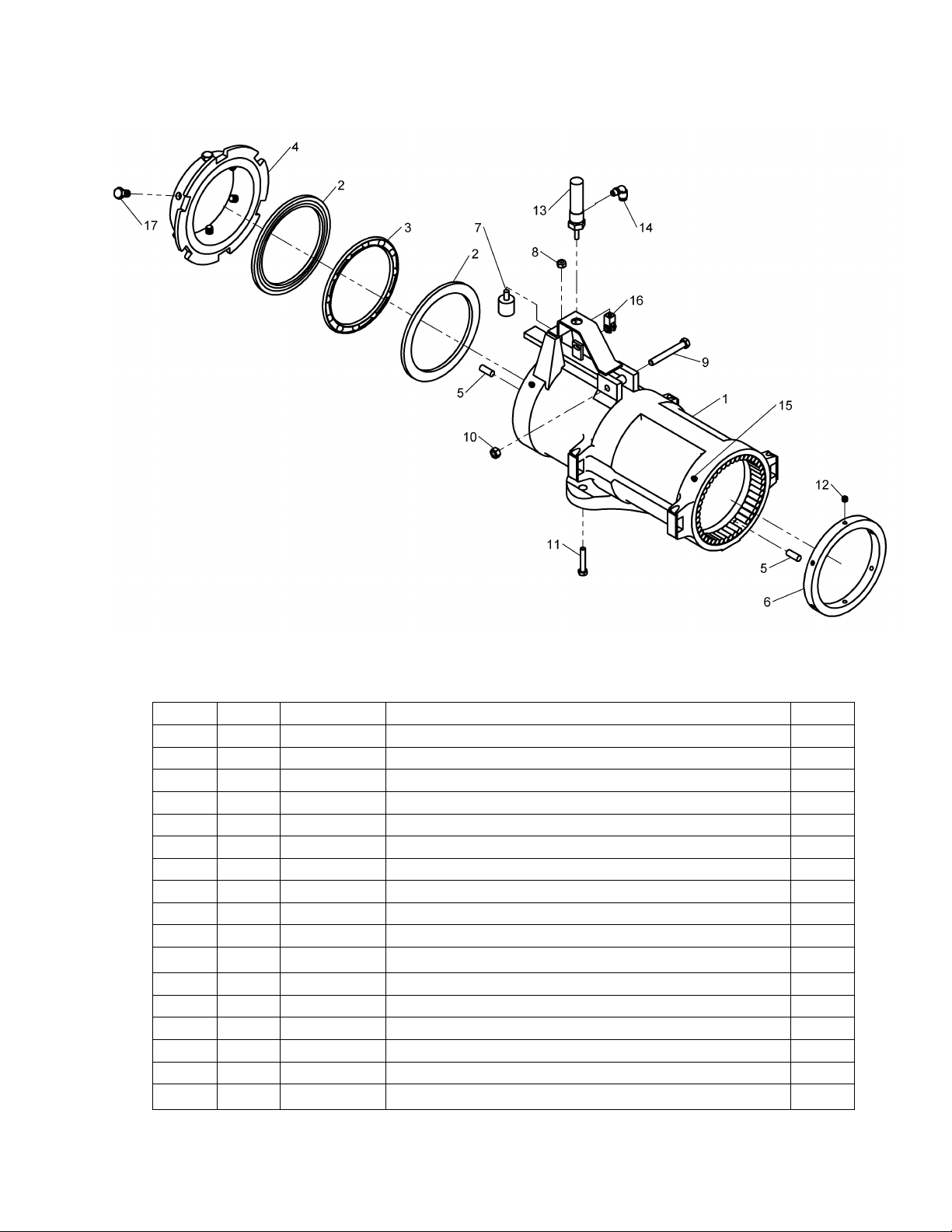
Housing Assembly (900-037)
ITEM
QTY
PART NO.
DESCRIPTION
1 1
950-050
HOUSING SUB ASSY.
2 2
107-005
BALL RACE
3 1
107-043
THRUST BEARING RETAINER
4 1
489-003
REAR COLLAR
5 98
281-001
ROLLER BEARING
6 1
489-002
FRONT COLLAR
7 1
10-0018
VIBRATION MOUNT
8 1
055-145
5/16-18 NYLON LOCK NUT
9 1
028-022
3/8-16 X 3 HHC SCREW
10 1 055-123
3/8-16 NC HEX NUT
11 2 028-016
5/16-18 X 1 3/4 HHCS SCREW
12
12
028-004
5/16 X 1/4 SOC SET SCREW
13 1 63-0014
AIR CYLINDER
14 1 096-346
1/8 NPT X 1/4 TUBE ELBOW FITTING
15 2 096-008
GREASE ZERK
16 1 53-0013
CYLINDER CLEVIS
17 6 028-005
7/16-14 X 3/4 HHC SCREW
Page 13
12
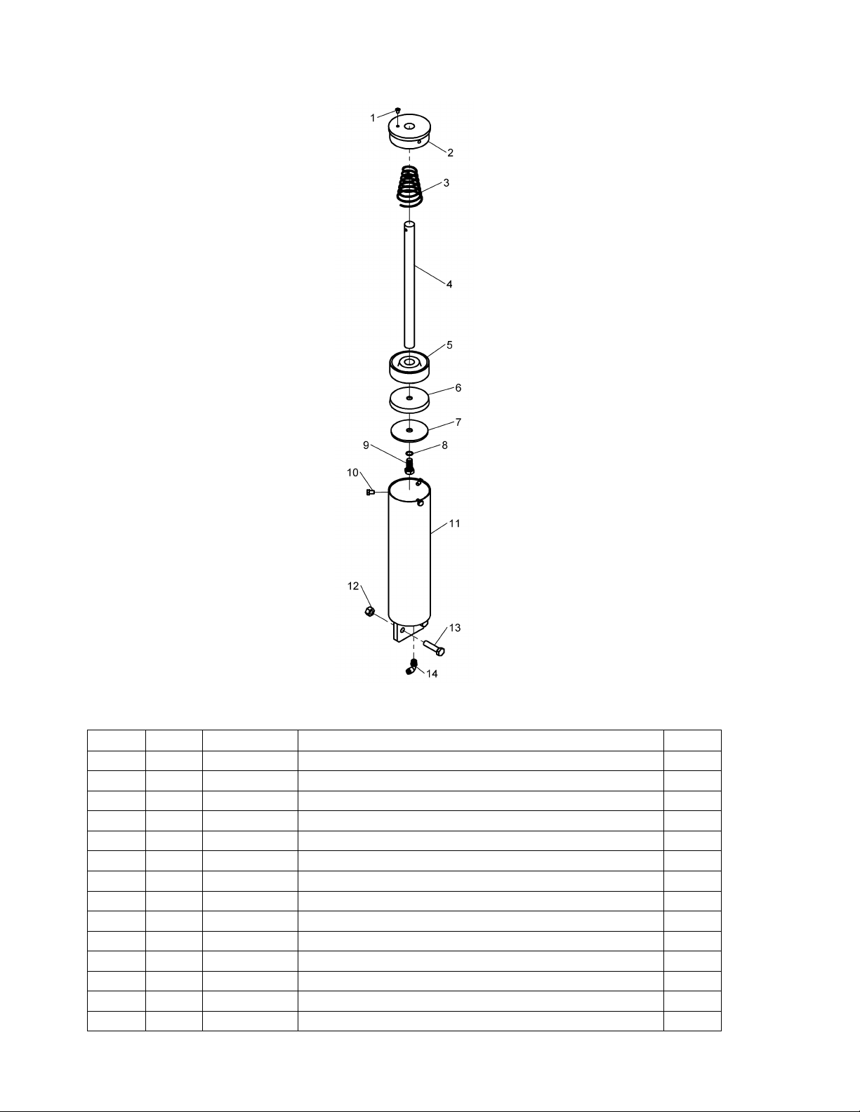
Lift Cylinder Assembly (900-016)
ITEM
QTY
PART NO.
DESCRIPTION
1 1
006-004
1/4 CAP PLUG
2 1 098-005
LIFT CYLINDER COVER PLATE
3 1 110-007
LIFT CYLINDER SPRING
4 1 149-011
LIFT PISTON ROD
5 1 051-026
LIFT PISTON
6 1 041-295
4 PISTON CUP
7 1 101-296
CUP RETAINER
8 1 167-240
14mm GASKET
9 1 028-239
9/16-12 X 1 1/4 HHC SCREW
10 3 028-280
5/16-18 X 1/2 HHC SCREW
11 1 005-030
LIFT CYLINDER TUBE
12 2 055-058
1/2-13 NC BI-WAY LOCK NUT
13 2 028-006
1/2 X 2 NC HHC SCREW
14 1 096-342
1/4 TUBE ELBOW FITTING
Page 14
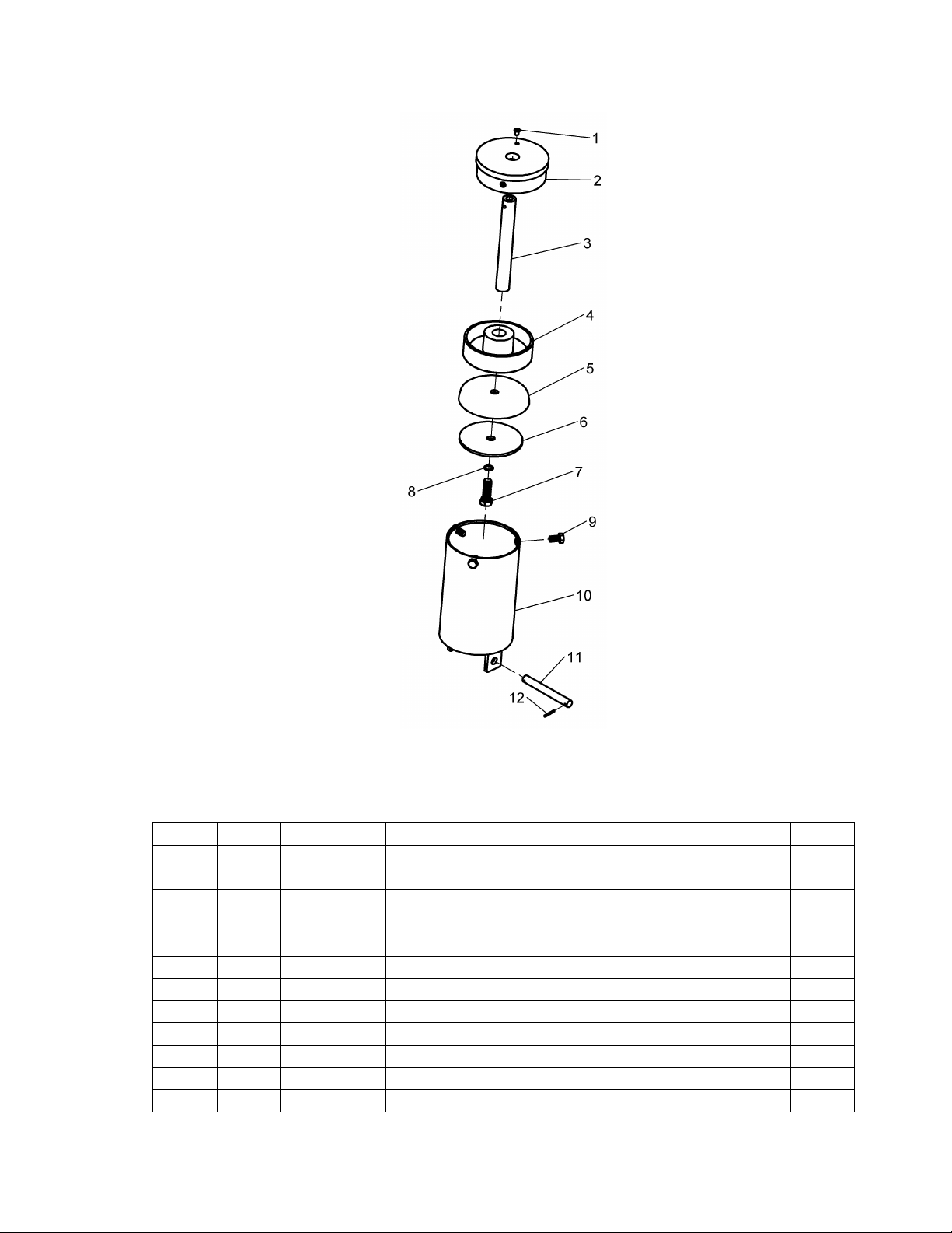
13
Diameter Arm Cylinder Assembly (900-043)
ITEM
QTY
PART NO.
DESCRIPTION
1 1
006-004
1/4 CAP PLUG
2 1 264-001
DIA. ARM CYLINDER
3 1 104-002
PISTON SHAFT
4 1 051-016
5 1/4 PISTON
5 1 041-009
5 1/4 PISTON CUP
6 1 101-033
PISTON PLATE
7 1 028-013
9/16-12 X 1 3/4 HHC SCREW
8 1 167-240
14 mm GASKET
9 3 028-005
7/16-14 X 3/4 HHC SCREW
10 1 030-006
CYLINDER TUBE
11 1 149-020
DIA. CYLINDER ROD
12 2 061-005
1/8 X 1 SPRING PIN
Page 15
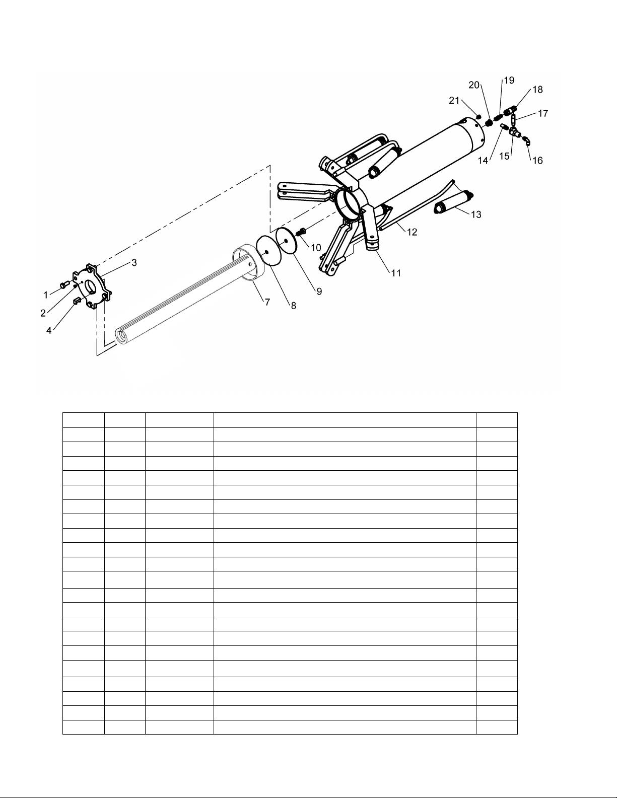
14
Spread Cylinder Assembly (900-028)
ITEM
QTY
PART NO.
DESCRIPTION
1 4
028-034
1/2-13 X 1 1/4 HHC SCREW
2 1
006-004
1/4 CAP PLUG
3 1
098-004
COVER PLATE
4 1
251-002
KEY 5 -
6 -
7 1 950-107
SPREAD ARM PISTON AND ROD
8 1
041-009
5 1/4 PISTON CUP
9 1
101-033
PISTON PLATE
10 1 028-239
9/16-12 X 1 1/4 HHC SCREW
11 1 103-009
SPIDER ARM
12 4 149-021
RETURN SPRING ROD
13 4 110-004
TENSION SPRINGS
14 1 885-035
1/4 NPT MUFFLER
15 1 190-085
QUICK EXHAUST VALVE
16 1 096-342
1/4 TUBE ELBOW FITTING
17 1 096-007
2" PIPE NIPPLE
18 1 034-027
QUICK COUPLER
19 1 096-170
1/4 TRU-FLATE NIPPLE
20 1 039-008
1/2 TO 1/4 PIPE BUSHING
21 1 096-004
1/4 NPT HSH PLUG
Page 16

15
COMMERCIAL WARRANTY
This product is warranted by BRANICK INDUSTRIES, INC. to the original user-owner against defective materials
or workmanship for a period of one year from the date of shipment. During the warranty period, at the discretion of
Branick management, if the product is found to be defective, it will be repaired or replaced without charge. For
service, contact Branick (800-437-4394) to obtain an RMA. Any product shipped to Branick must have an RMA
and proof of original shipment date. The repaired or replacement product will be returned with transportation
charges prepaid by Branick.
This warranty does not cover defects in the product caused by ordinary wear and tear, abuse, misuse,
overloading, accident (including shipping damage), improper maintenance, alteration, or any other cause not the
result of defective materials or workmanship.
REPAIR OR REPLACEMENT IS THE EXCLUSIVE REMEDY FOR DEFECTIVE PRODUCT UNDER THIS
WARRANTY. THIS WARRANTY IS EXPRESSLY IN LIEU OF ALL OTHER WARRANTIES, INCLUDING ANY
IMPLIED WARRANTY OF MERCHANT ABILITY OR ANY IMPLIED WARRANTY OF FITNESS FOR A
PARTICULAR PURPOSE OF THIS PRODUCT. BRANICK INDUSTRIES, INC. SHALL NOT BE LIABLE FOR
ANY CONSEQUENTIAL OR INCIDENTAL DAMAGES.
BRANICK INDUSTRIES, INC. reserves the right to make changes in the design or construction of our products
without obligation to incorporate such changes in products already sold and without notice.
Service parts and regular repair service are available from authorized distributors of Branick products, or from:
BRANICK INDUSTRIES, INC.
4245 Main Ave.
Fargo, North Dakota 58103
Toll Free: 800-437-4394
www.branick.com
© Copyright 2016 by Branick Industries, Inc. Printed in U.S.A.
 Loading...