

Page 1
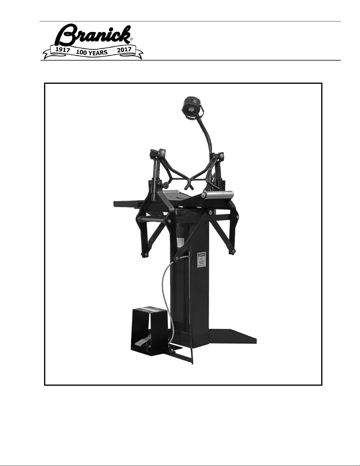
MODEL 5120
Tire Repair Station
00-0049
Installation, Operation
& Repair Parts
Information
Branick Industries, Inc. • 4245 Main Avenue • Fargo, North Dakota 58103
REV0081117 P/N: 81-0058G
Page 2
INSTALLATION
1) Position the Model 5120 on a solid level floor. Bolting it to the floor is recommended.
2) Attach valve assembly to base of machine with fasteners provided.
2) Attach a 1/4 NPT quick coupler nipple (not provided) into the fitting located on the treadle
valve assembly. Use 1/4 inch air hose with 100 p.s.i. minimum.
OPERATION
1) Position tire on rollers. Steady tire with hand and insert spread hooks between tire beads.
2) Adjust spread hooks to proper height for the tire size being repaired. The spread hook
arms are held in position with a hitch pin. To adjust the spread hook arms, pull the hitch
pin and move spread hook arm up or down to one of the four adjustment holes.
Most larger truck tires will use the uppermost adjustment holes. Both spread hook arms
must be adjusted to the same height.
3) Spread tire to desired width using the foot operated valve. If tire is lifted off tire rollers
when it is spread, the spread hook arms are positioned too high and should be lowered.
4) To rotate tire to new position, release air pressure and rotate tire on rollers.
5) The attached work light can be adjusted to most favorable position.
6) After tire repairs are complete, actuate foot valve to release spread hook pressure and
remove spread hooks from the tire bead.
CAUTION
Before using this product, read and fully understand the operating
instructions and all decals on the product. This is necessary to
prevent injury to the operator and damage to the product.
Use this product only for spreading and repairing tire casings. Do
not use this product for any other purpose.
Keep fingers and hands clear of spread hooks during tire spread.
Do not use this product if it is visibly worn, distorted or damaged.
Always wear appropriate eye protection.
Page 3
MAINTENANCE
MONTHLY – Remove the plug (see cylinder assembly drawing) from the cover plate of the
cylinder and put a few ounces (1/4 cup) of light weight oil into the opening.
Replace plug after adding oil.
YEARLY – Remove the cover plate, piston spring and piston rod assembly from the
cylinder. Wash the interior of the cylinder with kerosene or fuel oil and wipe
dry. Put in a few ounces (1/4 cup) of light weight oil and reassemble cylinder.
CAUTION
To prevent injury, before disassembling the cylinder, disconnect the
airline to the spreader and depressurize the cylinder using the foot pedal
to completely lower the tire cradle.
Page 4
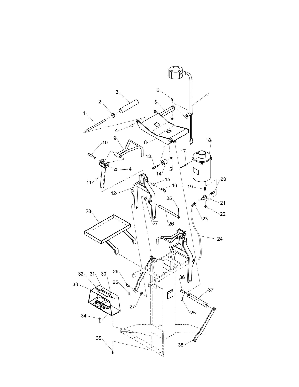
MAIN ASSEMBLY
Page 5

MAIN ASSEMBLY
ITEM
PART NO
QTY
DESCRIPTION
1 149-316
2
Roller Rod
2
107-094
4
Bearing
3
268-542
2
Roller
4
020-024
6
Press On Cap
5
055-145
3
5/16-18 Nylon Hex Lock Nut
6
028-012
1
5/16-18 X 3/4 Hex Head Cap Screw
7
40-0090
1
LED Lamp
8
03-0260
1
Tire Tray
9
03-0252
2
Spread Hook
10
54-0034
2
1/2 X 3 Clevis Pin
11
03-0261
2
Spread Hook Clevis
12
03-0258
2
Spread Arm
13
50-0072
2
3/8 X 1-3/4 Shoulder Screw
14
11-0046
2
Roller
15
110-065
2
Spring
16
04-0136
2
Stop Pin Kit
17
061-111
1
1/4 X 3-1/2 Spring Pin
18
01-0189
1
Cylinder Assembly
19
096-221
1
1/4 NPT Close Nipple
20
885-035
1
Muffler
21
190-085
1
Quick Exhaust Valve
22
055-103
2
3/8-16 Serrated Flange Lock Nut
23
096-342
1
1/4 NPT X 1/4 Tube 90° Fitting
24
D20-007
20”
1/4 OD Airline
25
061-035
10
5/32 X 1-1/4 Spring Pin
26
73-0605
2
Pivot Rod
27
039-097
4
5/8 Machine Bushing
28
03-0299
1
Tool Tray
29
54-0003
4
1/2 X 1 Clevis Pin
30
026-067
1
Spread Decal
31
026-300
1
Caution Decal
32
026-066
1
Release Decal
33
01-0244
1
Valve Assembly
34
055-160
2
1/4-20 Nylon Hex Lock Nut
35
028-010
2
1/4-20 X 3/4 Hex Head Cap Screw
36
54-0038
2
5/8 X 1-1/2 Clevis Pin
37
73-0599
2
Inner Offset Link
38
73-0600
2
Outer Offset Link
Page 6
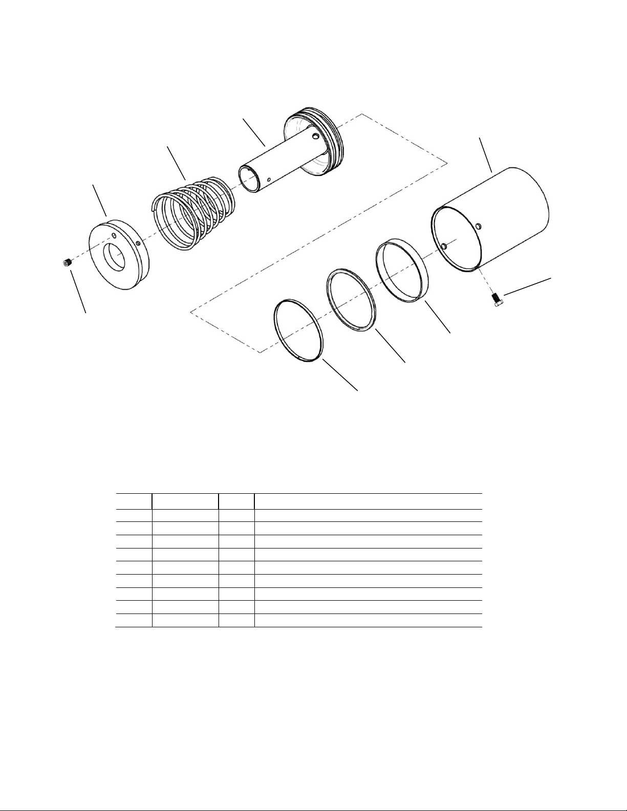
CYLINDER ASSEMBLY
SERIAL NO. 1826 AND LATER
ITEM
PART NO
QTY
DESCRIPTION
1 096-004
1
1/4" NPT Brass Hex Socket Head Plug
2 098-050
1
Cover Plate
3
110-001
1
Piston Spring
4
03-0262
1
Piston & Rod Assembly
5
D10-001
17.5”
Nylon Wear Strip
6
61-0038
1
5-5/8” Quad-Ring Seal
7
74-0306
1
Piston Spacer
8
028-005
4
7/16-14 X 3/4 Hex Head Cap Screw
9
03-0259
1
Cylinder Tube
1 2 3 4 9 8 7 6 5
Page 7
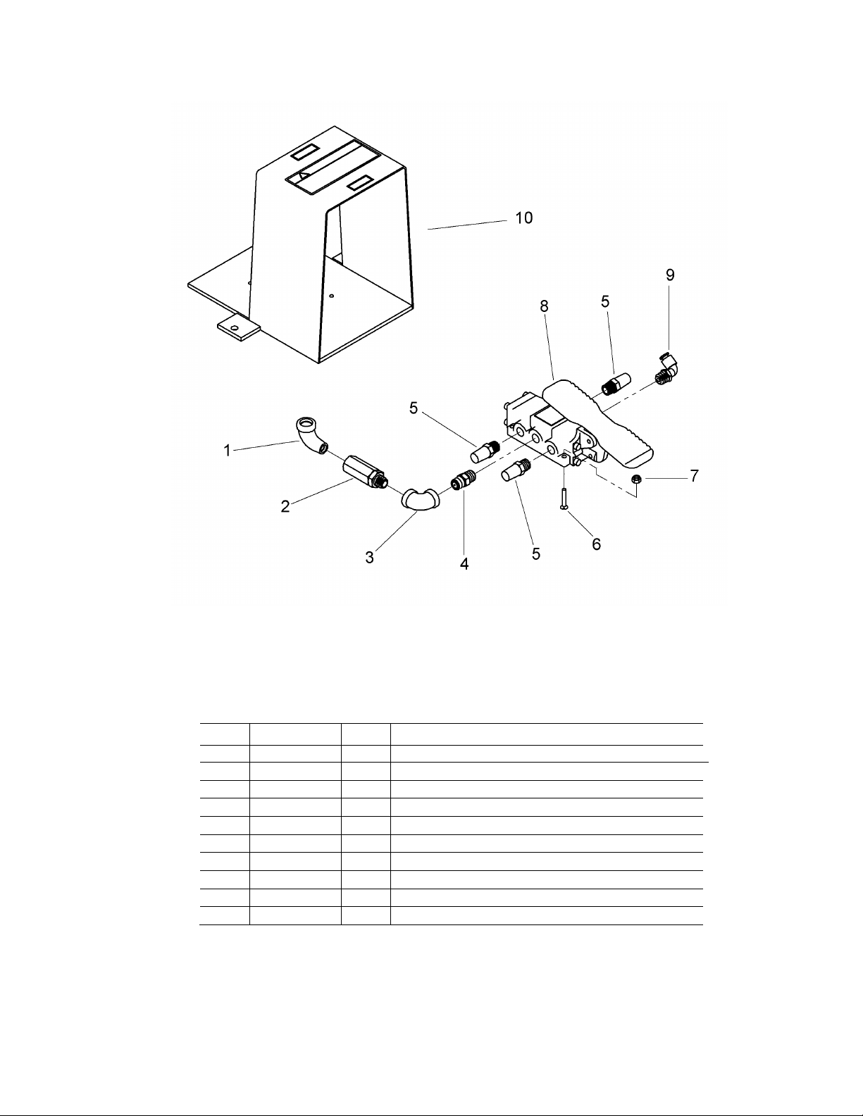
VALVE ASSEMBLY
ITEM
PART NO
QTY
DESCRIPTION
1 096-038
3
1/4 NPTF 90° Street Elbow Fitting
2 932-001
1
In-Line Filter
3
096-069
1
¼-90° FEMALE NPT ELBOW
4
096-162
1
1/4 NPT Restricted Hex Nipple Fitting
5
885-035
3
Valve Muffler
6
50-0041
4
8-32 X 1 FLAT HD MACH SCREW
7
055-082
4
8-32 Nylon Hex Lock Nut
8
60-0009
1
Foot Valve
9
096-342
1
1/4 NPT X 1/4 Tube MALE ELBOW
10
03-0431
1
Foot Valve Guard
Page 8

COMMERCIAL WARRANTY
This product is warranted by BRANICK INDUSTRIES, INC. to the original user-owner against defective materials
or workmanship for a period of one year from the date of shipment. During the warranty period, at the discretion
of Branick management, if the product is found to be defective, it will be repaired or replaced without charge. For
service, contact Branick (800-437-4394) to obtain an RMA. Any product shipped to Branick must have an RMA
and proof of original shipment date. The repaired or replacement product will be returned with transportation
charges prepaid by Branick.
This warranty does not cover defects in the product caused by ordinary wear and tear, abuse, misuse,
overloading, accident (including shipping damage), improper maintenance, alteration, or any other cause not the
result of defective materials or workmanship.
REPAIR OR REPLACEMENT IS THE EXCLUSIVE REMEDY FOR DEFECTIVE PRODUCT UNDER THIS
WARRANTY. THIS WARRANTY IS EXPRESSLY IN LIEU OF ALL OTHER WARRANTIES, INCLUDING ANY
IMPLIED WARRANTY OF MERCHANT ABILITY OR ANY IMPLIED WARRANTY OF FITNESS FOR A
PARTICULAR PURPOSE OF THIS PRODUCT. BRANICK INDUSTRIES, INC. SHALL NOT BE LIABLE FOR
ANY CONSEQUENTIAL OR INCIDENTAL DAMAGES.
BRANICK INDUSTRIES, INC. reserves the right to make changes in the design or construction of our products
without obligation to incorporate such changes in products already sold and without notice.
Service parts and regular repair service are available from authorized distributors of Branick products, or from:
BRANICK INDUSTRIES, INC.
4245 Main Ave.
Fargo, North Dakota 58103
Toll Free: 800-437-4394
www.branick.com
© Copyright 2018 by Branick Industries, Inc. Printed in U.S.A.
 Loading...