

Page 1
Branick Industries, Inc. • 4245 Main Avenue • Fargo, North Dakota 58103
REV120418 P/N: 81-0108G
Installation, Operation
& Repair Parts
Information
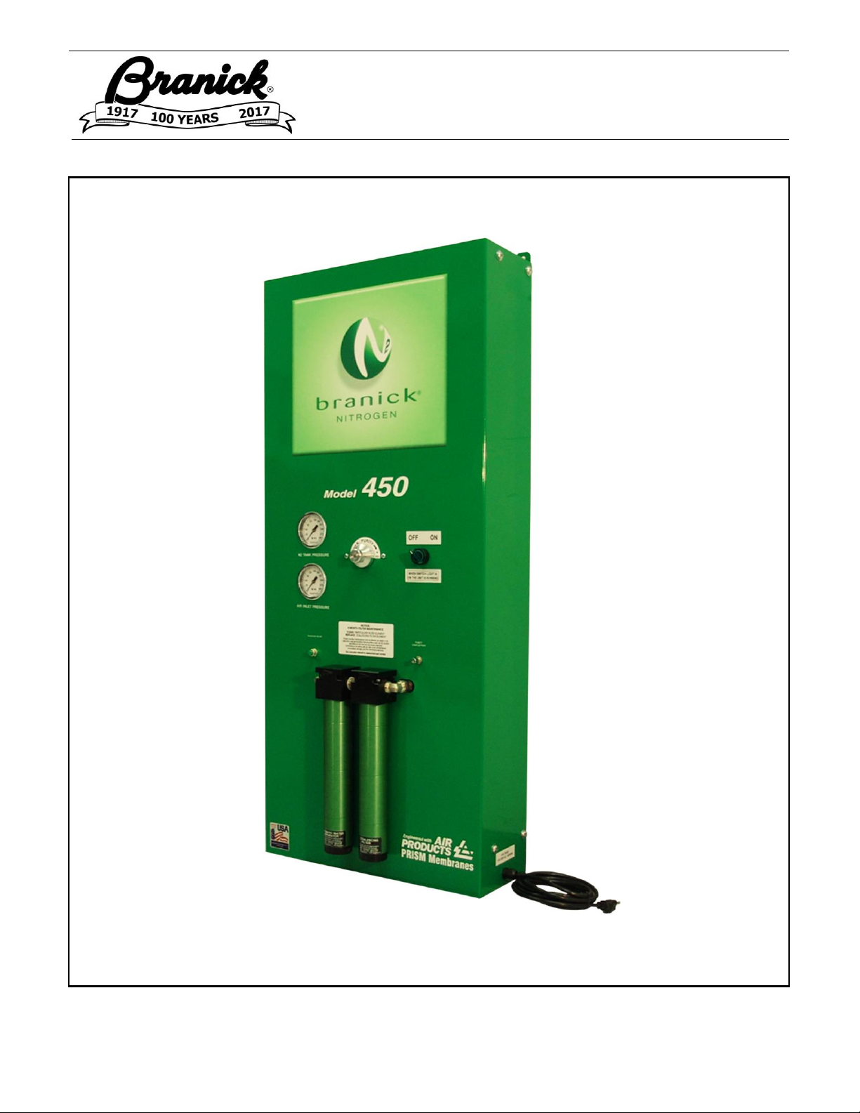
MODEL 450/650
NITROGEN INFLATION
SYSTEMS
Page 2

1
THIS PAGE INTENTIONALLY LEFT BLANK
Page 3

2
TABLE OF CONTENTS _______________________________________________________
SAFETY INSTRUCTIONS 2
DEFINITIONS 2
SPECIFICATIONS 3
INSTALLATION INSTRUCTIONS 4
OPERATING INSTRUCTIONS 4
COMPONENT IDENTIFICATION 5
MAINTENANCE 6
MODEL 450 REPAIR PARTS 7
MODEL 650 REPAIR PARTS 9
WARRANTY 11
SAFETY INSTRUCTIONS _____________________________________________________
▪ NEVER allow unauthorized personnel to operate this product.
▪ NEVER use this product for anything other than its intended use.
▪ THOROUGHLY train new employees in the proper use and care of this product.
▪ PROHIBIT unauthorized personnel from being in shop area while this product is in use.
DEFINITIONS _______________________________________________________________
▪ CAUTION: Indicates a potentially hazardous situation, which if not avoided, may result in damage to
property or minor personal injury.
▪ HAZARD: A source of potential injury to a person.
▪ MAINTENANCE: Those actions that preserve the correct and proper conditions under which the machine
shall be used. This may include adjustment, replacement of wear items, lubrication and cleaning, but not
modifications or repair of damage.
▪ MAY: This word is understood to be permissive.
▪ MUST: This word is understood to be mandatory.
▪ OPERATION: The correct and proper use of the machine as described in this manual.
▪ SAFETY ALERT SYMBOL: A symbol that indicates a potential personal safety hazard. It is composed of
an equilateral triangle surrounding an exclamation point.
▪ SHALL: This word is understood to be mandatory.
▪ SHOULD: This word is understood to be advisory.
▪ WARNING: Indicates a potentially hazardous situation, which if not avoided, may result in death or
serious personal injury.
Page 4
3
SPECIFICATIONS ___________________________________________________________
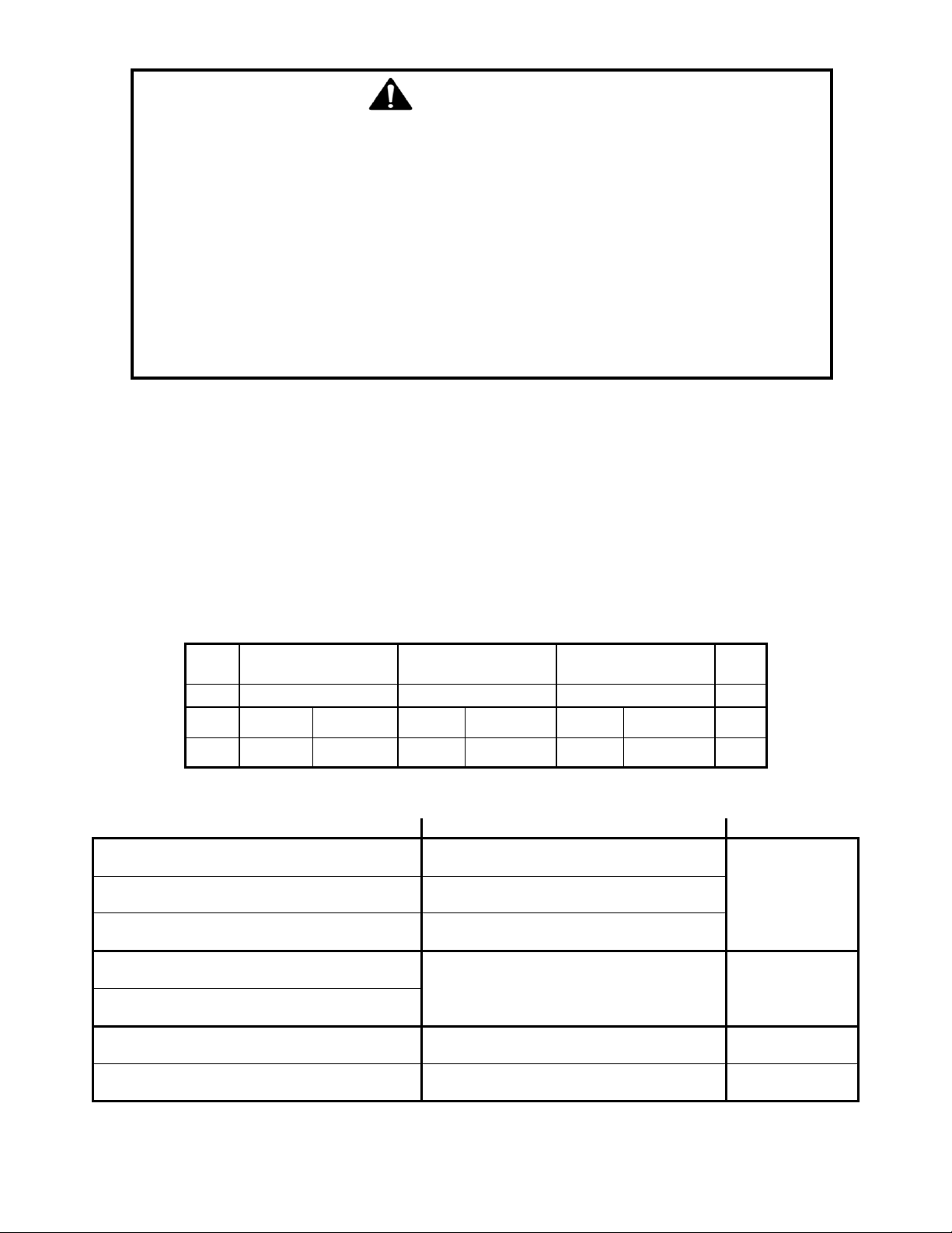
Operating Temperature 40° to 140° F (4° to 60° C)
Min/Max Compressed Air Supply 150 to 175 psi (10.3 to 12.0 bar)
Dimensional data 7.5 x 20 x 46.5 in (19 x 51 x 118 cm)
Weight Model 450 100 lbs (45.36 kgs)
Model 650 120 lbs (54.43 kgs)
Specifications shown below are at an air temperature of 75° F (24° C) and a supply air pressure of 160psi (11.0
bar). These specifications are intended to be a baseline to result in the production of 95% pure nitrogen. The
output flow of nitrogen has been pre-set to 4.3 scfm (6.9 Nm³/hr) per membrane. Changes to air temperature,
supply air pressure or supply air flow will change the result of nitrogen purity.
Model
Supply Air Pressure
Supply Air Flow
Maximum
Output N2 Flow
N2 # psi
bar
scfm
Nm³/hr
scfm
Nm³/hr
Purity
450
160
11.0
8.4
13.5
4.3
6.9
95%*
650
160
11.0
16.8
27
8.6
13.8
95%*
* These are minimum settings. The purity can be increased by rotating the purity adjustment dial clockwise
Change
Note
Result
When supply air temperature increases
Supply air flow requirement will increase
Nitrogen Purity
increases
When supply air pressure increases
When supply air flow decreases
N2 output flow will decrease
When supply air temperature decreases
Nitrogen Purity
decreases
When supply air pressure decreases
Rotating purity adjustment dial clockwise
N2 output flow will decrease
Increase Purity
Rotating purity adjustment dial ccw
N2 output flow will increase
Decrease Purity
CAUTION
Before using this product, read and fully understand operating
instructions and all decals on product. This is necessary to prevent
injury to operator and damage to product.
Do not attempt to use this product for anything other than its
intended purpose.
Use of this product should be in a suitably ventilated shop.
Operate valves slowly to prevent damage to coalescing filter.
Use of this product is only permitted in places free from explosion
or fire hazard.
Do not use this product if it is visibly worn, distorted or damaged.
Page 5

4
INTENDED USE _____________________________________________________________
This Nitrogen Inflation System is a pneumatic device designed to generate deoxygenated air for the purpose of
inflating vehicle tires.
INSTALLATION INSTRUCTIONS _______________________________________________
1. Unpack and remove unit from shipping carton and pallet.
2. Inspect unit for any visible damage.
3. Make sure installation location is free from explosion or fire hazard and is suitably ventilated.
4. Make sure plumbing from air compressor to nitrogen generator is made of an appropriately rated copper,
steel or aluminum and is at least 30 ft. in length.
5. Install on a solid level wall.
6. Anchor unit to wall with 3/8 anchor bolts (not supplied) utilizing four mounting tab holes on back of unit.
7. Connect air supply line from compressor to air inlet on side of unit.
8. Connect nitrogen supply line to nitrogen outlet on side of unit.
9. Plug cord into standard 110 V outlet.
NOTE: The nitrogen generator has a filter system that captures oil, water and other contaminants.
However, if your air supply system generates an excessive amount of water, etc., it may be
desirable to install an air dryer.
NOTICE:
The presence of any oil in the Nitrogen Membrane will void the
manufacturer’s warranty.
OPERATING INSTRUCTIONS _________________________________________________
Turning Nitrogen Generator ON
1. Turn power switch on front of unit, from “OFF” position to “ON” position.
2. If unit is connected to a storage tank, an automatic shut-off valve will stop flow of air to the nitrogen
generator when tank pressure reaches 160 psi. The automatic shut-off valve will open again to allow air
flow through nitrogen generator when tank pressure drops to 145 psi. This is done to prevent
unnecessary use of air compressor.
3. To sample purity of nitrogen being produced, use a nitrogen analyzer at sampling port just as you would
check a nitrogen filled tire.
NOTE: After nitrogen line is pressurized or nitrogen storage tank is filled, vehicle tires can be inflated.
Turning Nitrogen Generator OFF
1. Turn power switch on front of unit, from “ON” position to “OFF” position.
Purity Adjustment Instructions
1. Your nitrogen generator is equipped with a purity adjustment dial. Nitrogen purity is set to a minimum of
95%. To increase nitrogen purity, rotate the purity adjument dial clockwise. Maximum travel of the dial will
be approximately 270°.
NOTE: Increasing nitrogen purity will decrease nitrogen flow.
Page 6
5
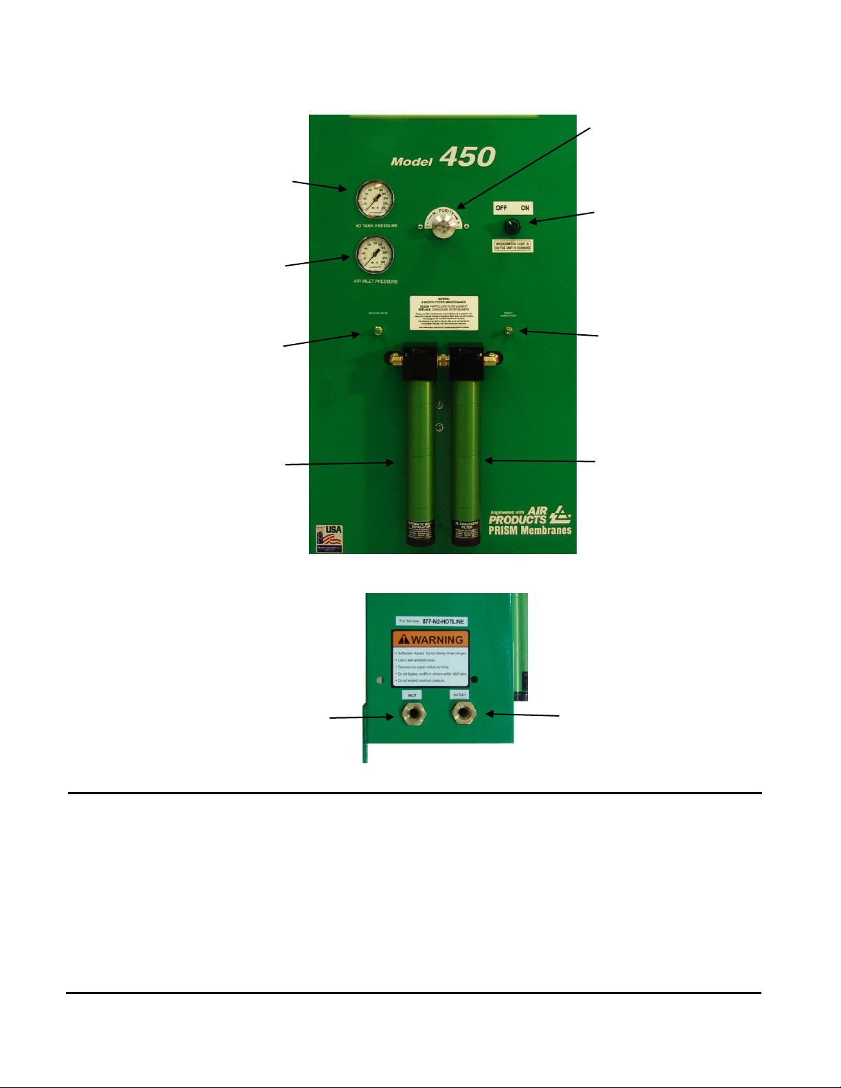
COMPONENT IDENTIFICATION________________________________________________
5 6 7 8 1
2 3 4
10
9
1
Nitrogen Outlet Pressure
6 Power Switch
2
Air Inlet Pressure
7 Purity Sample Port
3
Pressure Relief Valve
8 Coalescing Filter
4
Particulate Filter
9 Air Inlet Port
5
Purity Adjustment Knob
10 Nitrogen Outlet Port
Page 7

6
MAINTENANCE _____________________________________________________________
NOTE: To avoid personal injury or damage to Nitrogen Inflation System, permit only qualified personnel to
perform maintenance. When cleaning or replacing filter elements and automatic float drains, shut
off supply air by turning power button on front of unit to “OFF”. Press pressure relief button on
front panel to exhaust all trapped air. You can now service the filters.
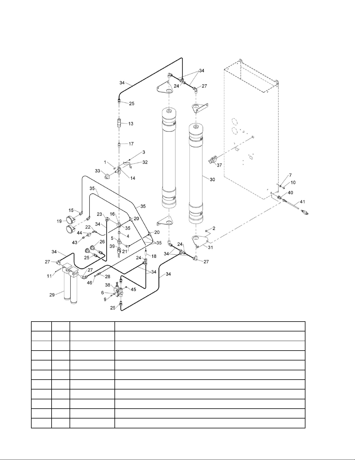
See repair parts breakdown for replacement parts.
ALWAYS: Keep Nitrogen Inflation System clean.
DAILY: Check the automatic float drain on all filters for proper operation.
If automatic float drain should become stuck open or inoperable, shut off air
supply (see NOTE above). Before servicing let pressure bleed off from filter.
Remove bottom cap from filter. Drain can be cleaned in hot soapy water. DO
NOT attempt to disassemble drain. If drain is still inoperable after cleaning, it will
have to be replaced. When installing a new drain, make sure o-ring is installed
on bottom stem before screwing it into the bottom cap. Finger tighten only.
WEEKLY: Clean automatic float drain on both filters.
See above.
BI-YEARLY: Clean particulate filter element and replace coalescing element.
___________________________________________________________________________
OWNER’S RECORDS
Date Installed: _______________________
Serial number _______________________ Located on back
___________________________________________________________________________
Page 8
7
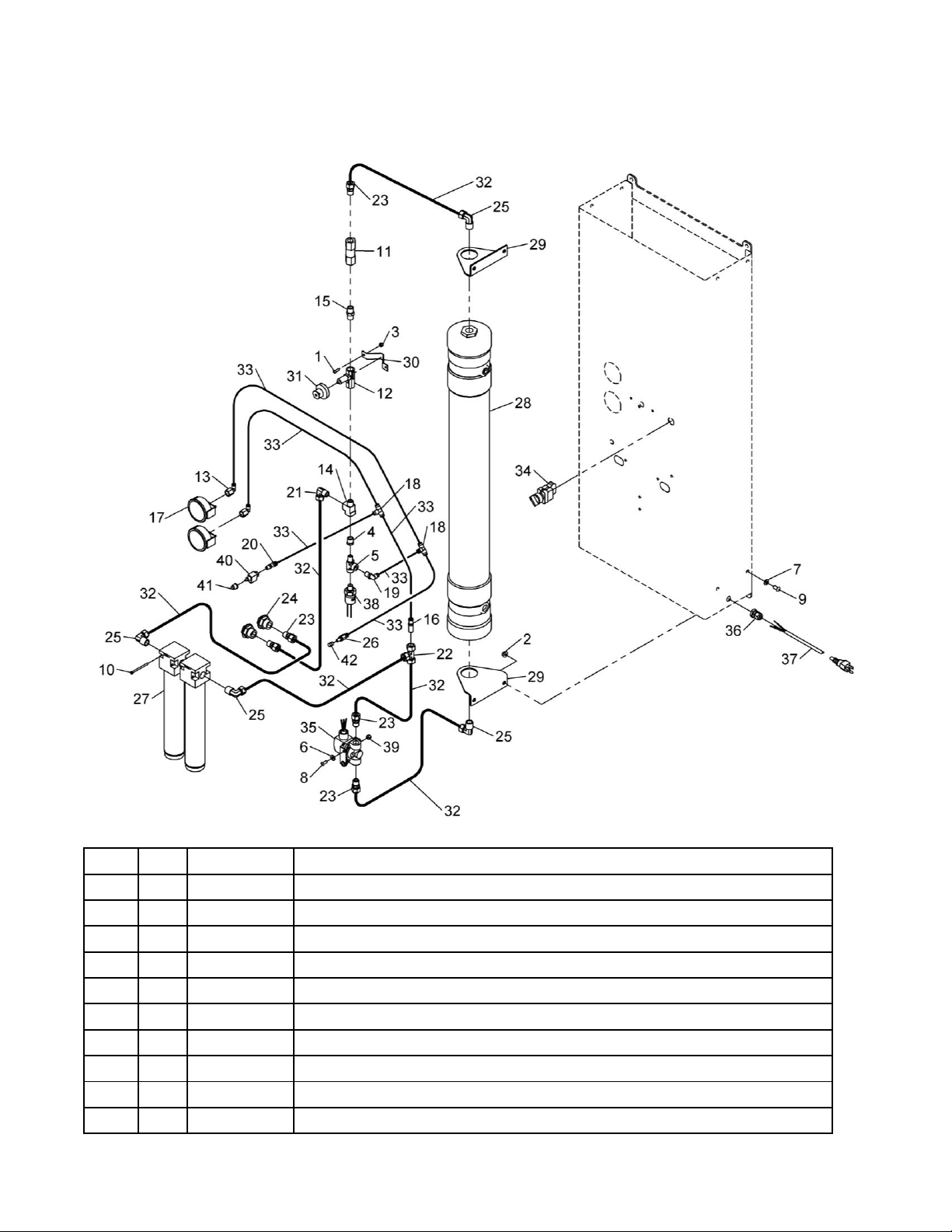
MODEL 450 REPAIR PARTS __________________________________________________
ITEM
QTY
PART NO.
DESCRIPTION
1 2 028-155
#10-24 X 5/8 RD HD SCREW
2 4 055-105
5/16-18 SF HEX LOCK NUT
3 2 055-127
#10-24 NYLOCK NUT
4 1 096-039
3/8-1/4 REDUCER BUSHING
5 1 096-155
1/4 NPT STREET TEE
6 2 108-110
1/4 SAE FLAT WASHER
7 4 108-123
5/16 SAE WASHER
8 2 50-0125
1/4-20 X 5/8 SOC BTN HC SCREW
9 4 50-0126
5/16-18 X 5/8 SOC BTN HC SCREW
10 2 50-0137
#8-32 X 2-1/2" PPHM SCREW
Page 9
8
ITEM
QTY
PART NO.
DESCRIPTION
11 1 60-0114
CHECK VALVE
12 1 60-0115
FLOW CONTROL VALVE
13 2 60-0124
1/4 X 1/4 NPT FEMALE ELBOW
14 1 60-0132
3/8 NPT STREET TEE
15 1 60-0134
3/8 NPT HEX NIPPLE
16 1 60-0139
REDUCER
17 2 60-0167
2-1/2" PSI PANEL MOUNT GAUGE
18 2 60-0171
1/4 UNION TEE
19 1 60-0172
1/4 X 1/4 NPT MALE SWIVEL ELBOW
20 1 60-0173
1/4 X 1/8 NPT MALE SWIVEL ELBOW
21 1 60-0175
1/2 X 3/8 NPT MALE ELBOW
22 1 60-0176
1/2 UNION TEE
23 5 60-0177
1/2 X 3/8 NPT MALE CONNECTOR
24 2 60-0178
3/8 NPT X 1-14 STR BULKHEAD COUPLING
25 4 60-0181
1/2 X 1/2 NPT MALE ELBOW
26 1 60-0196
1/4 SCHRADER BULKHEAD VALVE
27 1 64-0016
FILTER ASS'Y
28 1 64-0022
N2 MEMBRANE
29 2 72-0140
MEMBRANE BRACKET
30 1 72-0209
NEEDLE VALVE BRACKET
31 1 73-1100
PURITY ADJUSTMENT DIAL
32 D20-031
1/2 OD (BLACK) TUBE
33 D20-002
1/4 OD (GREEN) TUBE
34 1 64-0017
COALESCING FILTER ELEMENT *
35 1 41-0041
ILLUMINATED SELECTOR SWITCH
36 1 60-0326
SOLENOID VALVE (w/BRACKET)
37 1 40-0083
POWER CORD CABLE GRIP
38 1 42-0026
12 FT POWER CORD
39 1 41-0040
PRESSURE SWITCH (w/HARNESS)
40 2 055-160
1/4-20 NYLON HEX LOCK NUT
41 1 60-0140
SPOOL 2-WAY VALVE
42 1 69-0029
CAPTIVATED PUSH BUTTON
43 1 59-0021
CHROME BRASS VALVE STEM CAP
44 1 64-0021
MESH FILTER ELEMENT *
45 1 69-0020
AUTO FLOAT DRAIN *
46 1 50-0148
#8-32 X 3/8" HSHC SCREW *
47 1 40-0086
TERMINAL STRIP CONNECTOR *
* Items not shown
Page 10
9
MODEL 650 REPAIR PARTS___________________________________________________
ITEM
QTY
PART NO.
DESCRIPTION
1 2 028-155
#10-24 X 5/8 RD HD SCREW
2 8 055-105
5/16-18 SF HEX LOCK NUT
3 2 055-127
#10-24 NYLOCK NUT
4 1 096-039
3/8-1/4 PIPE BUSHING
5 1 096-155
1/4 NPT STREET TEE
6 2 108-110
1/4 SAE FLAT WASHER
7 8 108-123
5/16 SAE WASHER
8 1 108-168
#8 HELICAL LOCK *
9 2 50-0125
1/4-20 X 5/8 SOC BTN HC SCREW
10 8 50-0126
5/16-18 X 5/8 SOC BTN HC SCREW
Page 11
10
ITEM
QTY
PART NO.
DESCRIPTION
11 2 50-0137
#8-32 X 2-1/2" PPHM SCREW
12 1 50-0148
#8-32 X 3/8 HSHC SCREW *
13 1 60-0114
CHECK VALVE
14 1 60-0115
FLOW CONTROL VALVE
15 2 60-0124
1/4 X 1/4 NPT FEMALE ELBOW
16 1 60-0132
3/8 NPT STREET TEE
17 1 60-0134
3/8 NPT HEX NIPPLE
18 1 60-0139
REDUCER
19 2 60-0167
2-1/2" PSI PANEL MOUNT GAUGE
20 2 60-0171
1/4 UNION TEE
21 1 60-0172
1/4 X 1/4 NPT MALE SWIVEL ELBOW
22 1 60-0173
1/4 X 1/8 NPT MALE SWIVEL ELBOW
23 1 60-0175
1/2 X 3/8 NPT MALE ELBOW
24 3 60-0176
1/2 UNION TEE
25 5 60-0177
1/2 X 3/8 NPT MALE CONNECTOR
26 2 60-0178
3/8 NPT X 1-14 STR BULKHEAD COUPLING
27 6 60-0181
1/2 X 1/2 NPT MALE ELBOW
28 1 60-0196
1/4 SCHRADER BULKHEAD VALVE
29 1 64-0016
FILTER ASS'Y
30 2 64-0022
N2 MEMBRANE
31 4 72-0140
MEMBRANE BRACKET
32 1 72-0209
NEEDLE VALVE BRACKET
33 1 73-1100
PURITY ADJUSTMENT DIAL
34 D20-031
1/2 OD (BLACK) TUBE
35 D20-002
1/4 OD (GREEN) TUBE
36 1 64-0017
COALESCING FILTER ELEMENT *
37 1 41-0041
ILLUMINATED SELECTOR SWITCH
38 1 60-0326
SOLENOID VALVE (w/BRACKET)
39 1 41-0040
PRESSURE SWITCH (w/HARNESS)
40 1 40-0083
POWER CORD CABLE GRIP
41 1 42-0026
12 FT POWER CORD
42 1 40-0086
TERMINAL STRIP CONNECTOR *
43 1 69-0029
CAPTIVATED PUSH BUTTON
44 1 60-0140
SPOOL 2-WAY VALVE
45 2 055-160
1/4-20 NYLON HEX LOCK NUT
46 1 59-0021
CHROME BRASS VALVE STEM CAP
47 1 64-0021
MESH FILTER ELEMENT *
48 1 69-0020
AUTO FLOAT DRAIN *
* Items not shown
Page 12

11
Branick Industries, Inc.
Nitrogen Products
COMMERCIAL WARRANTY
(Non-Transferrable)
This product is warranted by BRANICK INDUSTRIES, INC. to the original user-owner against defective
materials or workmanship. During the warranty period, if Branick determines the product or components
to be defective, it will be repaired or replaced (at Branick’s option).
___________________________________________________________________________________________
Warranty Period
Labor: 12 months from the date of delivery.
Parts: 12 months from the date of delivery.
Nitrogen Membranes: 60 month warranty from the date of delivery. Proper pre-filter maintenance must
be followed as stated in this manual including changing filters every six (6)
months, and using ONLY filters purchased through Branick. Not doing so will void
the five year warranty. Contamination in the membrane including water, oil,
solvents, particles, and other contaminants will void the warranty. Connecting to
an airline with an oiler, or an unmaintained compressor will void the five
year warranty. In order for a membrane to be considered for warranty
replacement, it must be returned for inspection.
Service or Repair: Warranty service or repairs must be performed by a Branick designated service
company. Membranes replaced under warranty will remain under warranty for
the remaining portion of the original warranty period.
This warranty does not cover damage to the product caused by abuse, misuse, overloading, accident (including
shipping damage), improper maintenance, alteration, or any other cause not the result of defective materials or
workmanship.
Replacement is the exclusive remedy for defective product under this warranty. This warranty is expressly in lieu
of all other warranties, including any implied warranty of merchantability or any implied warranty of fitness for a
particular purpose of this product. Branick industries, inc. Shall not be liable for any consequential or incidental
damages.
BRANICK INDUSTRIES, INC. reserves the right to make changes in the design or construction of our products
without obligation to incorporate such changes in products already sold and without notice.
Service parts, warranty, and regular repair service for Nitrogen products are available Monday through Friday,
7:30am to 4:30pm CST.
BRANICK INDUSTRIES, INC.
4245 Main Ave.
Fargo, North Dakota 58103
1-877-N2-HOTLINE
Email: [email protected]
© Copyright 2018 by Branick Industries, Inc. Printed in U.S.A.
 Loading...