

Page 1

User Guide
GPS Time and Frequency System
Model GPS8 Plus
P/N 071000003
Revision 2.0
October 2004
Brandywine Communications
2230 South Fairview Street
Santa Ana, CA 92704
(714) 755 1050
(714) 755 0175
http://www.brandywinecomm.com
MANUAL P/N 900000007 REV 2.0
Page 2

Revision History
REVISION DATE COMMENTS
1.9 09-16-04 Preliminary release of GPS8 Plus user guide.
2.0 10-11-04 Revision of entire user guide.
2
MANUAL P/N 900000007 REV 2.0
Page 3
Safety Warnings
WARNING: This unit contains lethal AC voltages.
Disconnect the unit from the AC supply before removing
the cover.
WARNING:
The lightning flash with an arrowhead inside of an equilateral triangle is
intended to alert the user to the presence of un-insulated “dangerous
voltage” withi n the product’s enclosure. The “dangerous volt age” may be
of sufficient magnitude to constitute as a risk of electrical shock to people.
CAUTION:
The exclamation point inside of an equilateral triangle is intended to alert
the user to the presence of important operation and maintenance
instructions in the user guide.
3
MANUAL P/N 900000007 REV 2.0
Page 4

Table of Contents
1 Introduction ............................................................................................................................. 6
1.1 Scope of Section............................................................................................................ 6
1.2 Purpose of Equipment.................................................................................................... 6
1.3 Specification...................................................................................................................7
1.4 Controls, Indicators, and Connectors........................................................................... 11
2 Installation............................................................................................................................. 13
2.1 Scope of Section.......................................................................................................... 13
2.2 Unpacking and Inspection............................................................................................ 13
2.3 Installation and Testing ................................................................................................ 13
3 Operating Instructions........................................................................................................... 14
3.1 Scope of Section.......................................................................................................... 14
3.2 Operation...................................................................................................................... 14
3.3 Serial Communications ................................................................................................ 17
3.4 TxD1/RxD1 (Rear Panel J13) Baud Rate and Character Format................................ 18
3.5 TxD1/RxD1 (Rear Panel J13) User Commands and GPS8 Plus Responses ............. 19
3.6 Message Formats......................................................................................................... 22
3.6.1 Time and Date with Status, Position Averager Status, and Output Status ......... 22
3.6.2 Sounder Control .................................................................................................. 23
3.6.3 1
3.6.4 Dilution of Precision Values and Satellites Used................................................. 26
3.6.5 Time Code and Serial Data Output Formats ....................................................... 27
3.6.6 Frequency and Phase Controller Data ................................................................ 30
3.6.7 Health Status of Satellites ................................................................................... 36
3.6.8 Leap Second Information (Firmware 13+)........................................................... 37
3.6.9 2
3.6.10 Location and Signal Noise Ratio of Satellites...................................................... 39
3.6.11 Firmware Version Number................................................................................... 40
3.6.12 Offset of Local Time Data and Command........................................................... 41
3.6.13 Position of GPS Antenna..................................................................................... 42
3.6.14 Additional Information (Including Magnetic Declination) ..................................... 43
3.6.15 Request Precision Time ...................................................................................... 43
3.6.16 Software Reset Command .................................................................................. 44
3.7 TxD2/RxD2 Messages (Rear Panel J12)..................................................................... 45
3.7.1 Type 1 Format ..................................................................................................... 45
3.7.2 Type 2 Format ..................................................................................................... 45
3.7.3 Type 3 Format (GPS4 Format)............................................................................ 47
3.8 IRIG B and AFNOR NF 2 87-500 Time Code Output.................................................. 48
3.8.1 IRIG B and AFNOR NF 2 87-500 Time Code Bit Allocation ............................... 49
3.9 NASA36 Time Code Output......................................................................................... 51
3.10 2137 Time Code Output............................................................................................... 53
3.11 VELA Time Code Output (Slow Code)......................................................................... 54
3.12 Alarm Contacts (J14) ................................................................................................... 55
4 GPS8 Plus Keypad and Display Operation .......................................................................... 56
4.1 Scope of Section.......................................................................................................... 56
4.2 General Principles of Operation of Keypad and Display.............................................. 56
4.3 Messages after Power On............................................................................................ 57
4.3.1 Operating Mode Selection................................................................................... 58
4.3.2 GPS Locked Mode .............................................................................................. 58
4.3.3 Free Run Mode.................................................................................................... 59
4.3.4 1 PPS Lock Mode................................................................................................ 59
4.3.5 Manual Time and Date Entry............................................................................... 59
4.4 Position Screen ............................................................................................................ 60
4.5 Satellites Tracked Screen ............................................................................................ 60
4.6 1 PPS Status Screen ................................................................................................... 61
4.7 Mean Phase Screen..................................................................................................... 62
4.8 Estimated Mean Frequency ......................................................................................... 63
st
Pulse Output Data and Command (J10) ........................................................ 23
nd
Pulse Output Data and Command (PCB CON6 Pin 3).................................. 38
4
MANUAL P/N 900000007 REV 2.0
Page 5

4.9 Frequency Control........................................................................................................ 63
4.9.1 Test Configuration of Frequency Controller ........................................................ 64
4.10 Position Mode Configuration........................................................................................ 64
4.10.1 Position Mode Selection ...................................................................................... 65
4.11 Local Time Configuration ............................................................................................. 65
4.11.1 Local Time Offset Adjustment ............................................................................. 65
4.12 Time Code Configuration ............................................................................................. 66
4.12.1 Time Code Selection ........................................................................................... 66
4.12.2 J13 TXD1 Configuration ...................................................................................... 67
4.12.3 J12 TXD2 Configuration ...................................................................................... 67
4.13 J10 Pulse Output Configuration ................................................................................... 68
4.13.1 J10 Timed Pulse Configuration ........................................................................... 68
4.13.2 J10 Pulse Period Configuration........................................................................... 69
4.13.3 J10 Pulse Time Code Configuration.................................................................... 70
4.14 Status Screen and Alarm Configuration 1.................................................................... 71
4.14.1 Selection of Alarm Masks 1 ................................................................................. 71
4.15 Status Screen and Alarm Configuration 2.................................................................... 72
4.15.1 Selection of Alarm Masks 2 ................................................................................. 72
4.16 Status Screen 3............................................................................................................ 73
4.17 Status Screen 4............................................................................................................ 73
5 Principles of Operation.......................................................................................................... 74
5.1 Scope of Section.......................................................................................................... 74
5.2 Theory of Operation ..................................................................................................... 74
6 Maintenance and Calibration ................................................................................................ 77
6.1 Scope of Section.......................................................................................................... 77
6.2 Routine Maintenance ................................................................................................... 77
6.3 Fault Finding................................................................................................................. 78
6.4 Oscillator Module.......................................................................................................... 78
7 Diagrams............................................................................................................................... 79
8 Appendix I Output Alarm Masks ........................................................................................... 86
9 Appendix II Phase Noise....................................................................................................... 90
5
MANUAL P/N 900000007 REV 2.0
Page 6

1 Introduction
1.1 Scope of Section
Section 1 provides a general description of the GPS8 Plus. The introduction is
divided into three parts; purpose of the equipment, physical and electrical
specification, and an identification of the external controls, indicators, and
connectors.
1.2 Purpose of Equipment
The GPS8 Plus is a multi-output precision time and frequency standard that uses
the Global Positioning System (GPS) to steer and hold an internal oscillator and
clock system precisely on time. It is designed for use in telecommunications,
power utility, and military communication applications. Time and frequency
information is maintained to high accuracy by the internal oscillator even if no
satellites can be tracked. Each space vehicle in the GPS system transmits time,
frequency, and navigation information in two formats.
• P code: a precision code restricted to authorized users.
• C/A code: an unrestricted code available for general use.
In both cases the time information is maintained by the USA Department of
Defense and is traceable to the USA Naval Observatory. The standard GPS8
Plus uses the C/A code.
The GPS8 Plus provides a wide range of output options to form a complete time
and frequency management system. In addition, satellite data and navigational
information is outputted in the form of longitude, latitude, and altitude for
applications where precise positions must be known. For fixed position
operation, precise averaging of the position is carried out by the GPS8 Plus over
24 hours.
6
MANUAL P/N 900000007 REV 2.0
Page 7
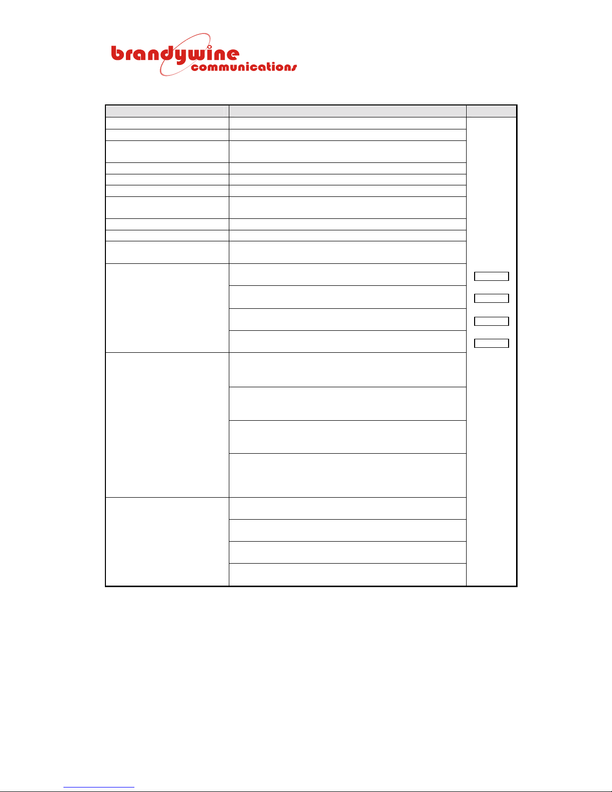
1.3 Specification
SPECIFICATION DESCRIPTION OPTION
Satellite Signal GPS L1 1.57542 GHz
Satellite Code C/A 1.023 MHz
Receiver Type Parallel eight channels (8 satellites tracked
continuously and simultaneously)
Receiver Sensitivity -133 dBm
Input Impedance 50 ohm
Standard Antenna Active omni-directional 30 dB gain
Cold Start Requirement Automatic (no time or position input needed)
Typically 8 minutes to time synchronization
Satellite Acquisition Time Typically < 20 seconds (warm start)
Data Update Rate 1 per second
Timing Accuracy Tracking
Satellites (XTAL_1)
Timing Stability Tracking
No Satellites
-Frequency Accuracy
-Tracking At Least One
Satellite
Frequency Stability
Tracking No Satellites
Within ±150 ns of GPS time
Standard deviation of 34 ns
Rubidium (Rb_2) oscillator
Better than 200 ns per hour
High stability OCXO (XTAL_1) oscillator
Better than 1 µs per hour
Standard OCXO (XTAL_2) oscillator
Better than 10 µs per hour
Temperature Compensated Crystal Oscillator (TCXO)
Better than 120 µs per hour
Rubidium (Rb_2) disciplined oscillator
1 s 10 s 100 s 1000 s 10000 s 100000 s
3E-11 1E-11 3E-12 3E-12 2E-12 8E-13
Precision OCXO (XTAL_1) disciplined oscillator
1 s 10 s 100 s 1000 s 10000 s 100000 s
2E-12 3E-12 1E-11 1E-11 3E-12 1E-12
Standard OCXO (XTAL_2) disciplined oscillator
1 s 10 s 100 s 1000 s 10000 s 100000 s
1E-9 2E-10 3E-10 3E-10 3E-11 1E-12
Temperature Compensated (TCXO) disciplined
oscillator
1 s 10 s 100 s 1000 s 10000 s 100000 s
1.5E-9 5E-10 4E-10 3E-10 3E-11 1E-12
Rubidium oscillator (Rb_2)
-11
5 x 10
High Stability OCXO (XTAL_1)
1 x 10
Standard OCXO (XTAL_2)
5 x 10
Temperature compensated (TCXO) oscillator
5 x 10
per month
-10
per day after 30 days of operation
-9
per day after 30 days of operation
-9
per day after 30 days of operation
7
MANUAL P/N 900000007 REV 2.0
Page 8
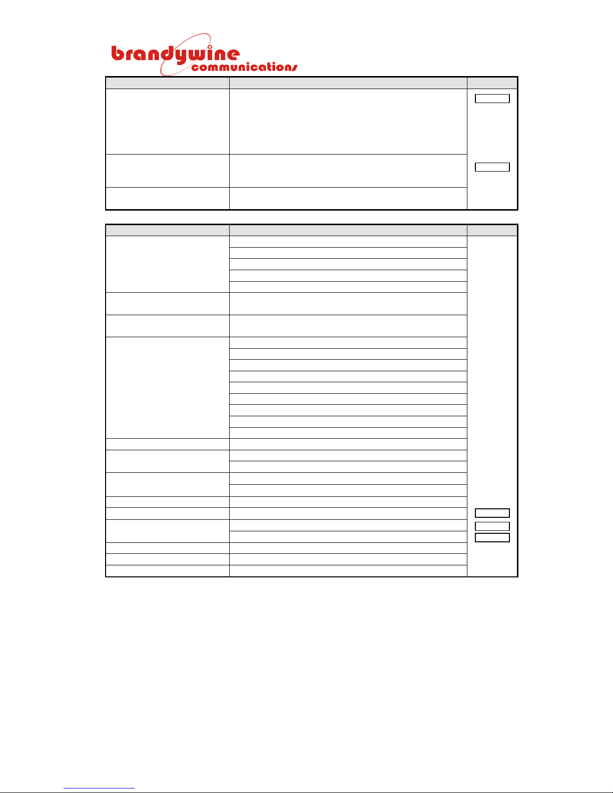
SPECIFICATION DESCRIPTION OPTION
Static Operation Standard
Deviation Position Average
(measured in northern
hemisphere over sixteen
24 hours averaged
positions)
Mobile Operation
Maximum Operational
Velocity
Disciplined Oscillator
Control Resolution (Rb_2)
2.3 meters N/S 1.9 meters E/W 5.0 meters Vertical
460 meters per second
-14
3 x 10
SPECIFICATION DESCRIPTION OPTION
Monitoring/Status
Indicators
Output Monitors 9 output monitor LEDs at each output socket for
Sounder Selectable audible marker of GPS receiver 1 PPS,
Built In Test
Manual Controls Primary power switch
Data Entry Option
Operating Temperature
Range
Humidity 95% non-condensing
Power Supply
DC Supply Options
Power Consumption 10 W typically
Case 19” 1U rack mounting 12.01 inches deep
Weight 12 lbs typically
Power LED (green)
Fault LED (red)
Time Valid LED (green)
Tracking Satellites LED (green)
Reject Data LED (yellow)
present signal (and status available via TxD1/RxD1)
Internal 1 PPS, or none
Antenna
Receiver
Initialization
Oscillator control
Oscillator frequency
Configuration parameters
Synthesizer phase-locked loop
RAM
FLASH/EPROM
4 way keypad
2 line LCD display
Instrument: -10 to +50°C
Antenna: -40 to +75°C
115/230 VAC ± 10% 45 - 65 Hz
48 VDC
24 VDC
8
MANUAL P/N 900000007 REV 2.0
Page 9
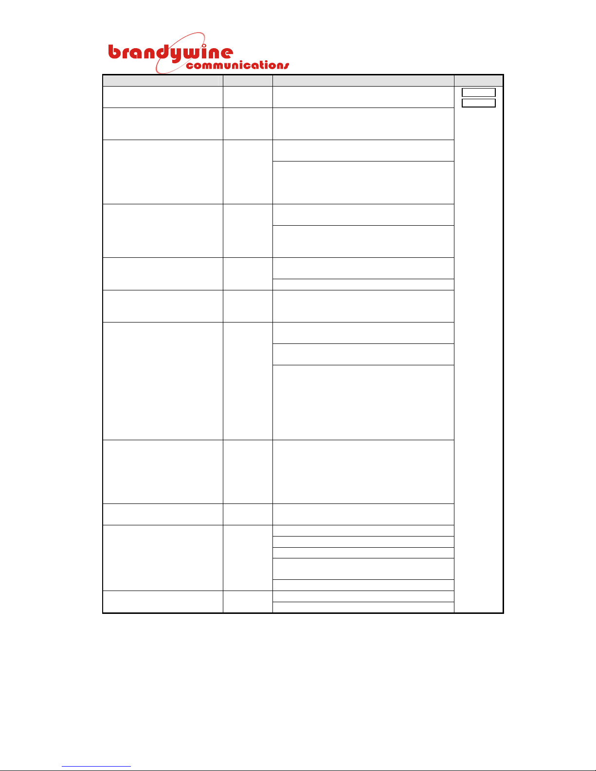
INPUTS AND OUTPUTS REF DESCRIPTION OPTION
Telecom Frequency
Options
Alarm J14
Option J10
1st Programmable Pulse
Output
2nd Programmable Pulse
Output
1 PPS J9
Code J8
See
Below
5-PIN din
180 DEG
9 way D
socket
9 way D
socket
50R BNC
50R BNC
PCB
ONLY
CON6
PIN 3
50R BNC
50R BNC
75R BNC
E1 2.048 MHz
T1 1.544 MHz
Free contacts from status monitor
changeover relay and center contact can
be linked to + 5 V or 0 V internally
TxD1/RxD1 RS232 (OR RS422 user
selectable inside)
User commands select and control output
types, request time data, frequency
controller data, GPS data, and instrument
output status
TxD2/RxD2 RS232 (OR RS422 user
selectable inside)
Automatic 1 per second time and status
output OR output on receipt of user time
request
Carries 5 VDC at center pin for powered
antennas
4 V output at 40 mA load
One digital (DCLS 0 to 5 V from 50R) time
code same as selected modulated time
code or is 1
User selectable 1st pulse rate in place of
the time code
Selected time code or pulse level 0 to 5 V
from 50R source
-1 pulse per 2 ms to 1 pulse per day, with
1 ms to 9999 ms pulse duration active
high or active low
-1 pulse per day, active high 100 ms is
the default value
-Pulse time accuracy (on and off) is UTC
±150 ns
-1 pulse per 2 ms to 1 pulse per day, with
1 ms to 9999 ms pulse duration active
high or active low
-1 pulse per minute, active high 100 ms is
the default value
-Pulse time is 350 µs early
1 PPS, 0 to 5 V square wave from 50R
One user selectable modulated time code
IRIG B AFNOR NASA36 VELA 2137
Level 2.17 Vpp carrier high level from 10R
Maximum 1.7 Vpp into 50R (internally
adjustable)
IRIG B is the default selection
8 KHz square wave (Telecom frame rate) 8 KHz J7
Square wave 0 to 5 V from 75R
st
pulsed output
Port 1 J13
Port 2 J12
GPS Ant J11
9
MANUAL P/N 900000007 REV 2.0
Page 10
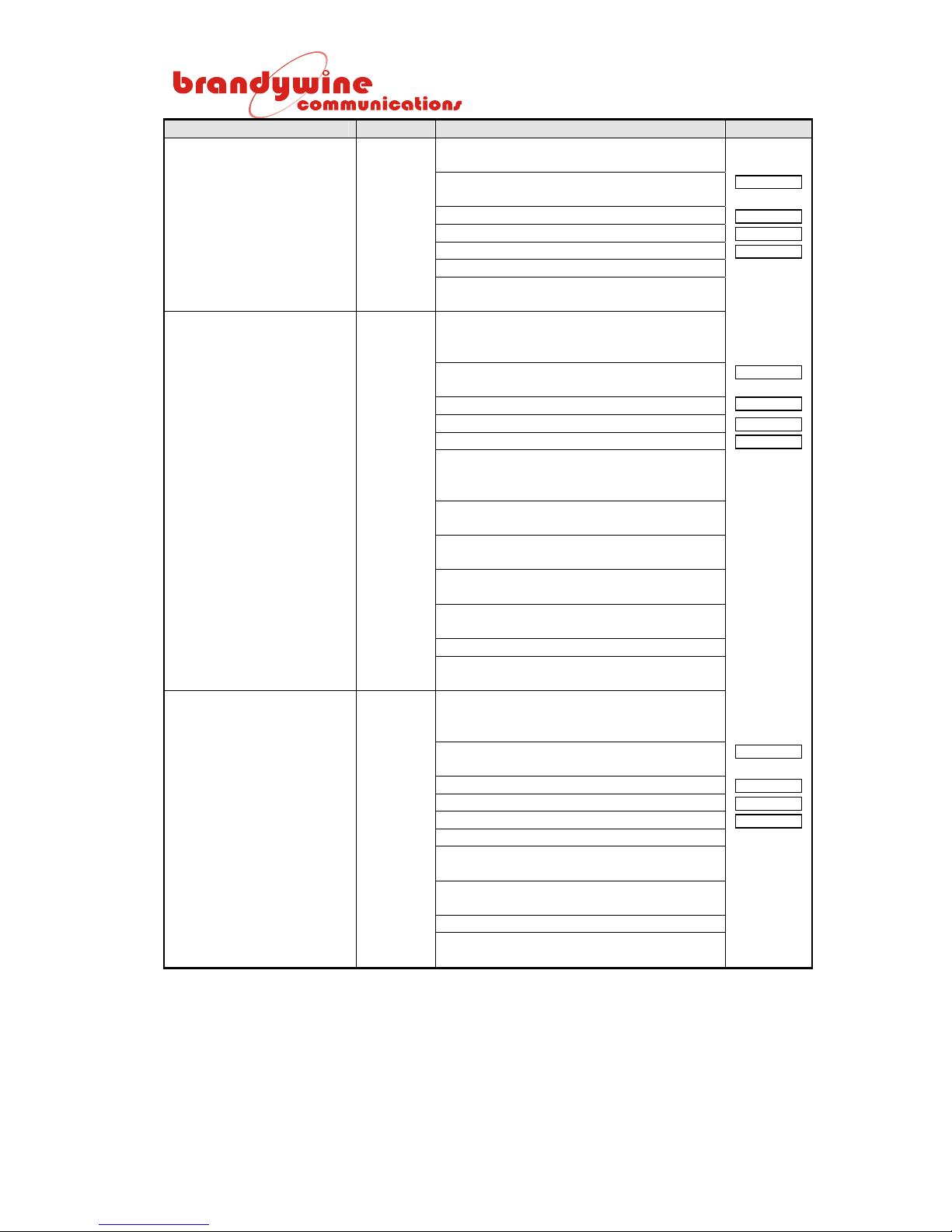
INPUTS AND OUTPUTS REF DESCRIPTION OPTION
Telco (two) J6 & J5
75R BNC
Freq 2 (two) J4 & J3
75R BNC
Freq 1 (two) J2 & J1
50R BNC
Outputs are link selectable (internally)
with the following options:
Telecom (2.048 MHz or 1.544 MHz as
selected above)
1 MHz (internal jumper selection)
5 MHz (internal jumper selection)
10 MHz (internal jumper selection)
Output level 0 to 5 V from 75R
Output level square wave 2.37 Vpp into
75R (G703 ¶ 6)
Outputs are from Bandpass filter module
2, specified at time of purchase, with the
following options:
Telecom (2.048 MHz or 1.544 MHz as
selected above)
1 MHz
5 MHz
10 MHz
Each output level 1 Vrms from 50R, 75R,
or 120R by internal jumper selection (50R
is the default)
Sine wave 3 Vpp from 75R meets G703 
10
Transformer isolation (75R connector
grounded to case)
Frequency accuracy and holdover similar
to tables above
Meets primary reference clock
requirements G811
Harmonic distortion -30 dBc or better
5 MHz or 10 MHz phase noise, see
Appendix II
Outputs are from Bandpass filter module
2, specified at time of purchase, with the
following options:
Telecom (2.048 MHz or 1.544 MHz as
selected above)
1 MHz
5 MHz
10 MHz
Output level 1 Vrms from 50R
Frequency accuracy and holdover as per
tables above
Transformer isolation (50R isolated
connectors)
Harmonic distortion -30 dBc or better
5 MHz or 10 MHz phase noise, see
Appendix II
10
MANUAL P/N 900000007 REV 2.0
Page 11
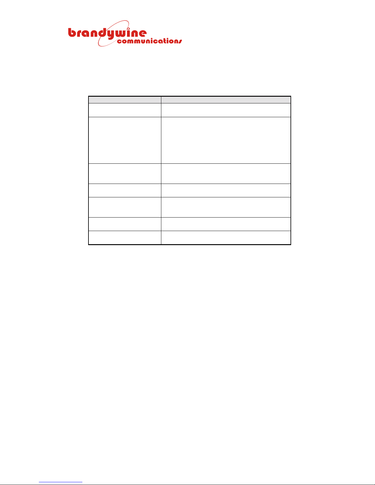
1.4 Controls, Indicators, and Connectors
Figure 1 and Figure 2 show the GPS8 Plus front panel, rear panel, indicators,
connectors, and controls. The following two tables below describe these
indicators, connectors, and controls.
INDICATOR DESCRIPTION
Power Green LED indicates that the primary power is
available.
Fault Red LED indicates one of the following:
1. Phase lock loop control voltage within
10% of its limit.
2. Synthesizer lost lock.
3. One or more output failures.
4. Processor malfunction.
5. No satellite reception for 8 hours.
Time Valid -Green LED indicates the time and position data
are synchronized since turned on.
-Turns off after no satellite reception for 8 hours.
Tracking Satellites Green LED indicates that at least one satellite is
being tracked.
Reject Data Yellow LED indicates that the last time data
frame was rejected (error bypass active and
frequency in holdover).
Display 2 lines, each with 24 characters low noise back-
lit liquid crystal display.
Keypad 4 way keypad for programming and display
control.
Table 1 GPS8 Plus Front Panel
11
MANUAL P/N 900000007 REV 2.0
Page 12
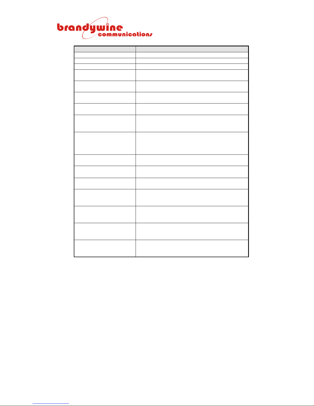
CONNECTOR/CONTROL DESCRIPTION
Primary Power 3 pin IEC socket for 115 VAC power
Fuse Main HT fuse for primary power supply
Alarm 5 pin 180° latching DIN socket
Port 1 9 way D type socket for serial RS232 or RS422
data communications
Port 2 9 way D type socket for serial RS232 or RS422
data communications
GPS Ant BNC socket (grounded) 50R for antenna signal
and power
Option
Option Status
1 PPS
1 PPS Status
Analog Code (IRIG B,
AFNOR, NASA36, VELA,
and 2137)
Analog Code Status
8 KHz
8 KHz Status
Telco
Telco Status 2
Telco
Telco Status 1
Frequency 2
Frequency 2 Status 2
Frequency 2
Frequency 2 Status 1
Frequency 1
Frequency 1 Status 2
Frequency 1
Frequency 1 Status 1
-BNC socket (grounded) 50R DC pulse output
-Green LED showing pulse output is active
-BNC socket (grounded) 50R 1 PPS output
referenced to UTC
-Green LED showing 1 PPS output is active
-BNC socket (grounded) 50R (with optional
galvanic isolation)
-Green LED showing analog code output is active
-BNC socket (grounded) 75R
-Green LED showing 8 KHz output is active
-BNC socket (grounded) 75R
-Green LED showing Telco output 2 is active
-BNC socket (grounded) 75R
-Green LED showing Telco output 1 is active
-BNC socket (grounded) 75R
-Green LED showing frequency 2 output 2 is
active
-BNC socket (grounded) 75R
-Green LED showing frequency 2 output 1 is
active
-BNC socket (isolated) 50R
-Green LED showing frequency 1 output 2 is
active
-BNC socket (isolated) 50R
-Green LED showing frequency 1 output 1 is
active
Table 2 GPS8 Pl us Rear Panel
12
MANUAL P/N 900000007 REV 2.0
Page 13

2 Installation
2.1 Scope of Section
Section 2 describes the procedure prior to and during the GPS8 Plus installation.
2.2 Unpacking and Inspection
Carefully remove the GPS8 Plus from the shipping carton. The following items
should be included in the shipment:
• 1 GPS8 Plus
• 1 power cord
• 1 user guide
2.3 Installation and Testing
The standard GPS8 Plus is housed in a 19” 1U rack mounting case, which can
be installed in a rack using the front panel mounting slots.
The active high gain antenna is a sealed omni-directional device, which must be
mounted with the cable exit at the bottom. For optimum performance the unit
should be located outside on a roof, away from objects which may impair satellite
visibility or generate high frequency interference.
Before connecting power to the receiver check that the power supply is in
accordance with the specification and/or details on the rear panel and check that
the power cord has a secure earth connection. An initial self test should be
carried out before final installation or connection to other units. The power
indicator will be illuminated. After about nine seconds the unit will test all the
software controlled indicators in the following order:
1. Fault
2. Time Valid
3. Tracking Satellites
4. Reject Data
If all LEDs are turned on simultaneously, an internal hardware fault has been
detected by the processor. The diagnostic messages from TxD1 (SK2/J13)
during power on should be examined for a fault report.
After the indicators have been tested they will be set to reflect the current status.
At this point the unit can be switched off and finally installed or configured as
described in section 3.
13
MANUAL P/N 900000007 REV 2.0
Page 14

3 Operating Instructions
3.1 Scope of Section
Section 3 covers the operation, initialization, and configuration of the GPS8 Plus.
It is assumed that the unit has been installed in accordance with section 2.3 and
that power has been applied to the unit.
3.2 Operation
During normal operation the GPS8 Plus automatically receives, analyses, and
processes data from up to eight GPS satellites simultaneously. This data is used
to provide time, frequency, and position information. The information is made
available to the user through a range of output interfaces.
In applications where the unit is to be used for general test and measurement
purposes, it can be switched on and off as necessary. However, if the unit is to
be used as a time and/or frequency standard it should be running continuously to
allow long term software processing to take place, which is essential if the unit is
to achieve its optimum performance. With the internal ovened oscillator XTAL_1
option, this process takes a minimum of 24 hours. The unit carries out automatic
position averaging and then automatically shifts into the known position to obtain
the highest possible time and frequency precision. The position averaging
process also takes place during the first 24 hours after the unit is switched on.
As described in section 2.3 when the GPS8 Plus is switched on it will carry out a
self-test routine before entering the operational program, which sets the correct
initial conditions for the receiver system. Satellite tracking is automatic, provided
that at least one is visible and the GPS8 Plus already has a valid position in its
battery backed receiver. Now time and frequency control can start within
approximately 1 minute. If three or more satellites are visible, the 3-D position
information will also be processed. The GPS8 Plus internal frequency standard
will warm up in 5 minutes (OCXO) or 10 minutes (Rubidium). At the end of the
warm up period the frequency controller is reinitialized.
Reception of at least one satellite is confirmed by the green Tracking Satellites
indicator being illuminated. Subsequent synchronization of the time to UTC (up
to 15 minutes from satellite reception) is confirmed by the green Time Valid
indicator being illuminated. The voltage control of the internal oscillator
maintains synchronization of all outputs with GPS. If the control voltage of the
internal oscillator is within 10% of the end-of-range, the red Fault indicator will
illuminate. This indicator also illuminates if any of the 10 outputs that should be
present are not detected by the internal output signal detector.
14
MANUAL P/N 900000007 REV 2.0
Page 15

The final phase and frequency locking process may take several hours
depending on the oscillator type fitted and satellite reception. Because the GPS8
Plus uses a patented "Intelligent Phase Locked Loop" system that incorporates a
specially developed dynamic time constant, the control parameters are
continuously modified to achieve lock in the shortest possible time to optimize its
performance for the best time and frequency accuracy.
Note that after a position has been successfully navigated, the number of tracked
satellites drops down to 4 or less, the satellite receiver automatically selects 2-D
positioning mode, and continues to recover time. If the number of tracked
satellites then drops down to 3, 2, or 1, the positioning mode is suspended but
time is recovered. If no satellites are tracked, the GPS8 Plus runs in ‘holdover’
continuing to maintain all the outputs. After 8 hours of lost reception the red
Fault indicator is turned on.
If the unit has a current satellite ephemeris at switch on, the start up time (after
system initialization has been completed) is approximately:
• Initial acquisition : 1 – 15 seconds
• Satellite re-acquisition : 25 seconds
• Tracking: 20 seconds
• Navigating: 1 minute from start up
• Position averaging complete: 24 hours from start up
Synchronization of the receiver time will normally be completed within 1½
minutes after the unit is switched on. If the receiver does not have an almanac
already backed up in memory after it has been switched on, it will take typically 8
or 9 minutes to acquire the necessary parameters to enable precise time
acquisition, as indicated by the Time Valid indicator on the GPS8 Plus front panel
or by the assertion of the Time Valid status bit in the time message.
For fixed position operation, precise averaging of the position is carried out by
the GPS8 Plus over 24 hours. The reason for this averaging is depicted in the
illustration below. The illustration shows the raw time data before processing is
carried out by the GPS8 Plus is improved by a factor of 3 when the GPS8 Plus
has averaged its position. The vertical scale on the graphs is the 1 PPS
deviations in nanoseconds.
15
MANUAL P/N 900000007 REV 2.0
Page 16
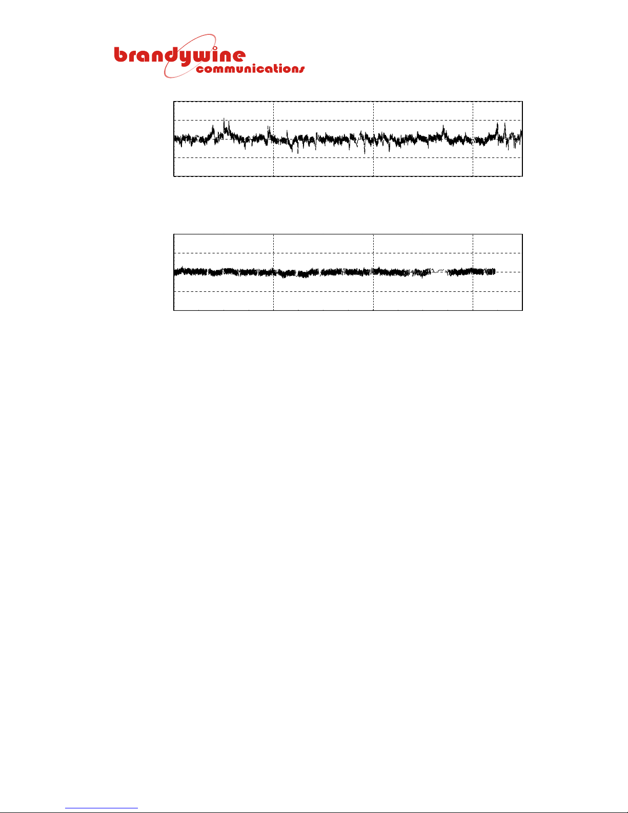
RAW 1PPS DATA FROM G PS RECEIVER - POSITION FINDIN G
500
250
0
-2 5 0
TIME DEVIATION IN ns
-5 0 0
0 4 8 12
Elapsed Tim e in Hours
RAW 1PPS DATA FROM GPS RECEIVER - POSITION AVERAGED
500
250
0
-2 5 0
TIME DEVIATION IN ns
-5 0 0
0 4 8 12
E lap s e d tim e in H o urs
Illustration 1 GPS8 Plus Averaging Position Result
FUR3.LOG
FUR4.LOG
16
MANUAL P/N 900000007 REV 2.0
Page 17
3.3 Serial Communications
The GPS8 Plus has two asynchronous serial ports that communicate with the
user. They are suitable for connection to other units such as printers, computers,
and terminals. They can be configured as RS232 or RS422 ports by turning
around a simple header inside the unit. The options fitted to this unit are
identified in the specification (section 1.3). This section describes the options in
more detail.
Each serial port is accessible via its own 9 way D socket, J13 and J12
respectively. An RS232 and RS422 selection header is mounted inside of the
unit just behind each of the 9 way D sockets on the main PCB. The header has
five straps traversing a standard 16 pin dual-in-line footprint at one end. If
inserted with the straps at the right-hand end viewed from the front of the main
PCB, the configuration of the associated connector is RS422 as defined in the
table below:
PIN GPS8 PLUS RS422
FUNCTION
1 Ground 0 V
2 Not used 3 Tx data- Output
4 Rx data+ Input
5 Ground 0 V
6 Rx data- Input
7 Not used 8 Tx data+ Output
9 Not used -
Table 3 RS422 Connections J13 and J12 (Factory Default)
If the header is inserted with the straps at the left-hand end viewed from the front
of the main PCB, the configuration of the associated connector is RS232 as
defined in the table below:
PIN GPS8 PLUS RS232
FUNCTION
1 Ground 0 V
2 Tx data Output
3 Rx data Input
4 Not used Input
5 Ground 0 V
6 Not used (RS422 Rx data-)
7 Not used 8 Not used (RS422 Tx data+)
9 Not used -
Table 4 RS232 Connections J13 and J1 2 ( Factory D ef ault)
Note that the unused pins (6 and 8) have RS422 signal connections, if a 5-way
jumper is used to select RS232. This can be eliminated by using a 3-way jumper
for RS232 selection. The 3 jumpers are at the left-hand end of the header
viewed from the front of the main PCB for RS232 selection.
17
MANUAL P/N 900000007 REV 2.0
DIRECTION
DIRECTION
Page 18
3.4 TxD1/RxD1 (Rear Panel J13) Baud Rate and Character Format
TxD1 is designed for communication with the user because it gives the user
access to the unit status and GPS reception information. RxD1 receives
commands and data requests from the user.
SW1 (a red 8-way switch pack) located on the main PCB controls TxD1/RxD1
baud rate and character format at J13. Prior to the alteration of the switch,
disconnect the power connection to the GPS8 Plus and practice all normal safety
precautions when opening the unit to access the 8-way DIL switch SW1.
SWITCH 1 2 3 4 5 6 7 8
ON For baud rate selection see
the table below
OFF No parity Even
Table 5a TxD1/RxD1 Character Format
SW1-1 SW1-2 SW1-3 SW1-4 BAUD
OFF OFF OFF OFF 75
ON OFF OFF OFF 110
OFF ON OFF OFF 134.5
ON ON OFF OFF 150
OFF OFF ON OFF 300
ON OFF ON OFF 600
OFF ON ON OFF 1200
ON ON ON OFF 1800
OFF OFF OFF ON 2400
ON OFF OFF ON 4800
OFF ON OFF ON 4800
ON ON OFF ON 9600
OFF OFF ON ON 9600
ON OFF ON ON 19200
OFF ON ON ON 19200
ON ON ON ON 19200
Table 5b TxD1/RxD1 Baud Rate
Parity Odd
parity
parity
8 data
bits
7 data
bits
2 stop
bits
1 stop bit
The example below is of the SW1 setting for 4800 baud, 8 data, no parity, and
1 stop:
!!!!
!!!!
!!!! !!!!
!!!!
OFF
ON
!!!!
!!!!
!!!!
12345678
Example 1 SW1 Factory Default Setting
18
MANUAL P/N 900000007 REV 2.0
Page 19
3.5 TxD1/RxD1 (Rear Panel J13) User Commands and GPS8 Plus
Responses
The GPS8 Plus asynchronous serial port RxD1/TxD1 provides time, position, and
status data on request from the user. Furthermore, it can accept user
commands. For example, to set the output time to UTC or local, the user must
set the local time offset from the UTC, set the pulse length on-time or period, and
set the duration of an output pulse in 1 millisecond units.
The user can obtain information from the GPS8 Plus by sending single ASCII
character requests terminated by <CR><LF>. The GPS8 Plus response
message structure is based on the NMEA-0183 standard for interfacing Marine
Electronics Navigation Devices. The same structure is used for commands from
the user that sets the GPS8 Plus operating parameters. User characters are
sampled at 1 millisecond intervals and will be missed if more than 1 character is
received per millisecond. If there is no time delay between the characters sent to
the GPS8 Plus, the maximum baud rate for the user commands is 4 800.
The requested record will be directed to the GPS8 Plus serial port TxD1 output.
All characters transmitted by the GPS8 Plus are consistent with ASCII character
or control codes. When hexadecimal numbers are transmitted to communicate
status bit values they are transmitted as ASCII characters 0 through 9 and A
through F (A through F characters are always upper case characters).
Reserved characters are used to indicate the beginning and end of records in the
data stream and to delimit data fields within a record. As an exception the time
request may be a single character and optionally without termination to minimize
the overhead of obtaining a time stamp response from the GPS8 Plus.
Example 2 ASCII Character Request
19
MANUAL P/N 900000007 REV 2.0
Page 20

The list of reserved characters is given in the table below:
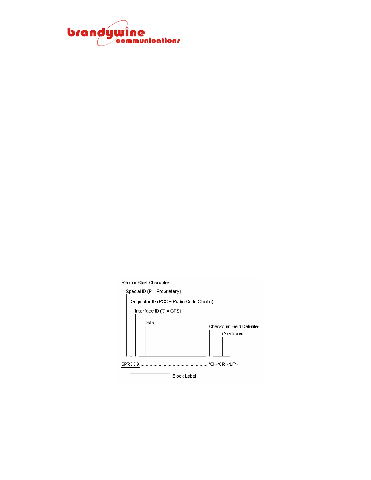
CHARACTER H EX VALUE USAGE
$ 24 Start of record identifier
<CR><LF> 0D 0A End of record identifier
, 2C Record field delimiter
* 2A Checksum field delimiter
Table 6 Rese rved Characters
The notation ‘CK’ indicates the optional checksum value of the message that is
computed by an exclusive-OR of all bytes between the ‘$’ and ‘*’ characters. The
‘$’, ‘*’, and checksum are not included in the checksum computation. For
commands sent to the GPS8 Plus, the checksum may be omitted in which case
the associated ‘*’ must also be omitted. The GPS8 Plus will recognize the <CR>
as the end of the message and will not attempt to verify the missing checksum. If
the checksum is attached by the user, it will be checked by the GPS8 Plus and
the message will be rejected if an error is detected. Errors in the format of the
message will also cause a rejection.
The list of available single character requests is given in the table below:
REQUEST RESPONSE
a<CR><LF> Version number, time, position averager, and output status information
b x<CR><LF> Sounder control, where x = 0, 1, or 2
c<CR><LF> 1st pulse output (local/UTC) time or pulse period, polarity, and pulse length
d<CR><LF> Dilution of precision values and satellites used
e<CR><LF> Modulated time code, pulsed output, TxD1 format, and TxD2 format
f<CR><LF> Frequency and phase controller data
h<CR><LF> Health status of satellites
j<CR><LF> Leap second date and UTC-GPS seconds offset value
k<CR><LF> 2nd pulse output (local/UTC) time or pulse period, polarity, and pulse length
l<CR><LF> Location and signal strength of satellites (up to three records)
n<CR><LF> Version number of firmware and GPS engine
o<CR><LF> Run UTC/local time and local time hours offset
p<CR><LF> Position of GPS receiver antenna
S<CR><LF> Additional information (including magnetic deviation)
t Precision time request *
Z See software reset command 3.6.16
Table 7 Single Character Request s
* The precision time request is handled as a priority. The ‘t’ request does not
need to be followed by a <CR><LF>. If a <CR><LF> is appended, it will be
ignored.
20
MANUAL P/N 900000007 REV 2.0
Page 21

The GPS8 Plus continuously polls the GPS receiver for satellite status and
associated information. If the user request requires information from the GPS
engine, the GPS8 Plus immediately forwards the information it has already
acquired in its internal buffer. The associated response is returned immediately.
If several requests have been sent prior to completion of the responses, the
order of responses may be different from the order of requests.
The precision time request is given high priority. The time at which the request
character was received is logged at the next whole millisecond and the GPS8
Plus transmits as soon as the serial port is free. This special message is not in
the NMEA format, but in the industry standard Type 2 Serial Data Format that is
described below in section 3.6.15.
21
MANUAL P/N 900000007 REV 2.0
Page 22
3.6 Message Formats
3.6.1 Time and Date with Status, Position Averager Status, and Output
Status
Requested by a<CR><LF>
Field 1 2 3 4 5 6 7 8
$PRCCG, A, 007, 19:53:19, 07/06/00, 9, 3, 1, 0000, 00*09
FIELD CONTENTS OF FIELD
1 Fixed text “A”
2 Version number of GPS8 Plus firmware 000 to 999
3
4 The status is the ASCII representation of a hexadecimal character between 0
5 Number of position average samples accumulated (target is 100)
6 Position average mode:
7 The output status (16 bits in 4 digits) as detected by the output detectors at
8 The control status (8 bits in 2 digits) as reported by the frequency controller.
BIT 15 BIT 14 BI T 13 BIT 12 BI T 11 BIT 10 BIT 9 BIT 8
Reserved Reserved Reserved Reserved Reserved Option fail 1 PPS fail Modulated
J10 (SK4) J9 (CON8) J8 (SK3)
BIT 7 BIT 6 BI T 5 BIT 4 BI T 3 BIT 2 BIT 1 BIT 0
Synthesizer
PLL
unlocked
J7 (SK12) J6 (SK10) J5 (SK8) J4 (SK9) J3 (SK11) J2 (SK7) J1 (SK6)
BIT 7 BIT 6 BI T 5 BIT 4 BI T 3 BIT 2 BIT 1 BIT 0
One or
more OP
failures
detected
Hours minutes seconds
Day of month, month, and year
and F. Each bit of the hexadecimal character represents the following status
condition when set to 1 (or the opposite at 0):
Bit 3 (MSB) Bit 2 Bit 1 Bit 0 (LSB)
Valid time Not GPS locked Local time Leap year
“0” = not averaging
“1” = averaging
“2” = known averaged position in use
each of the 10 sockets. Each hexadecimal character represents 4 bits and
each bit that is set to 1 corresponds to the status described in the following
tables below when true. When no failures are detected, four zeros are
transmitted.
Each bit that is set to 1 corresponds to the status described in the following
table below when true.
code fail
Table 8a Field 7 Bits
(LSB)
8 KHz fail Telco fail Telco fail Freq 2 fail Freq 2 fail Freq 1 fail Freq 1 fail
Table 8b Field 7 Bits
(LSB)
No
satellites for
8 hours
Reserved Oscillator
frequency
control near
its limit
Table 9 Field 8 Bits
MANUAL P/N 900000007 REV 2.0
Frequency
error
oscillator
cannot be
controlled
22
Reserved Rubidium
oscillator
status shows
rubidium cold
Reserved
Page 23

3.6.1.1 Example of Output
$PRCCG, A, 007, 13:56:48, 09/06/00, 9, 100, 2, 0000, 00*0B
The meaning of the response is i.e. software version 007, requested at 13 hours
56 minutes 48 seconds, on the 9
th
of June 2000, time status shows time valid,
synchronized, and UTC in leap year. The 100 position samples have been
accumulated so the position averaging is complete, the GPS receiver is reporting
that it is in a known position, and there are no output or control failures.
3.6.2 Sounder Control
Requested by b< >0 <CR><LF>
The GPS8 Plus sounder can be turned on and off by this command. The sound
output can be triggered by the GPS receiver 1 PPS (provided that the satellites
are being received and the position has been found) or it can be initiated by the 1
PPS derived from the GPS8 Plus precision time base. Note that there is a space
between the command letter ‘b’ and the control number 0, 1, or 2. The three
commands are as follows:
• b 0<CR><LF>: satellite receiver 1 PPS initiates the sound
• b 1<CR><LF>: GPS8 Plus internal 1 PPS initiates the sound
• b 2<CR><LF>: the sounder is turned off
3.6.3 1
st
Pulse Output Data and Command (J10)
Requested by c<CR><LF>
Sending the single letter ‘c’ followed by <CR><LF> requests a message from the
GPS8 Plus that describes its 1
format transmitted to the GPS8 Plus sets the pulse output parameters, which are
stored in non-volatile RAM. The 1
st
pulse output from J10. The same message
st
pulse output (logic levels 0 V and 5 V from
50R) can be commanded to be normally low going high for the pulse duration or
normally high going low for the pulse duration. There are two ways to specify the
pulse occurrence and duration. Also, note that the output at J10 can be
commanded to be a time code, see the ‘e’ command.
1. The pulse output can be specified to occur at the UTC or local time. In
this case, the pulse outputs always start at the second’s edge (UTC to
within ±150 ns) and terminate at a specified number of milliseconds later.
The ‘don’t care’ characters in the pulse time definition allow hour, minute,
or second values to be ignored. The default pulse output setting is UTC
midnight and positive pulse 100 ms long. The minimum and maximum
pulse duration is 1 ms and 9999 ms respectively.
23
MANUAL P/N 900000007 REV 2.0
Page 24

2. Alternatively, multiple pulses per time period can be specified. In this
case, the period of the pulse stream is specified together with the pulse
active duration. The minimum period is 2 ms and the maximum period is
9999 ms. Immediately after receipt of the command, the current pulse (if
active) is terminated and the first new pulse commences at the start of the
next second’s edge. If the pulse period specified in milliseconds is a submultiple or a multiple of seconds, the pulses remain synchronized with 1
PPS. If the contrary is true, the pulses may require multiple seconds
before the start of a pulse coincides with 1 PPS. However, they are
always strictly related to real-time milliseconds as long as the unit is
locked to the GPS.
Remember that if the checksum is omitted in the user command to the GPS8
Plus, the ‘*’ must be omitted from the end of the message so that the GPS8 Plus
recognizes that no checksum is available. Two forms exist as seen below:
• Form 1 (pulse output at specified time, local or UTC):
Field 1 2 3
$PRCCG, C, UHHMMSS, +9999*CK<CR><LF>
• Form 2 (pulse output with specified period):
Field 1 2 3
$PRCCG, C, P9999, +9998*50<CR><LF>
FIELD CONTENTS OF FIELD
1 Fixed text letter “C”
2
3 ‘+’ = pulse output when active is +5 V from 50R, when inactive is 0 V from 50R.
9999 From 1 to 4 digits (leading zeros NOT required) defines the pulse length in
EITHER
‘U’ = UTC of the pulse output time or ‘L’ = local time of the pulse output time.
Followed by HHMMSS = hour minute second of the pulse output time, where
leading zeros MUST be present in the time field (e.g. 5 hours is 05 hours).
If HH or MM or SS are to be ignored, XX is transmitted (where X = ASCII code
58 hexadecimal).
OR
‘P’ = specified period in milliseconds, which is the following number 2 to 9999.
‘–’ = pulse output when active is 0 V from 50R, when inactive is +5 V from 50R.
milliseconds.
Note that the GPS8 Plus responds to the pulse setting command by echoing the
message that is recomputed from the values originally transmitted by the user
after they have been decoded for use by the GPS8 Plus and its own checksum
has been added to the message output. Illegal commands are ignored, except
when the pulse length is commanded to be greater than the pulse period. In this
case, the pulse length is reset to 1 ms.
24
MANUAL P/N 900000007 REV 2.0
Page 25
3.6.3.1 Examples of 1
Note that the examples of the 1
st
Pulse Commands and Responses
st
pulse commands and responses are when the
UTC or local time is specified.
1. $PRCCG, C, L202500, +100*79<CR><LF>
The pulse output commences at 20 hours 25 minutes 00 seconds local
time and is active at +5 V for 100 ms.
2. $PRCCG, C, UXXXXXX, +1*65<CR><LF>
The pulse output commences once per second and is active at +5 V for 1
ms.
3. $PRCCG, C, UXXXX10, -500*66<CR><LF>
The pulse output commences once per minute at 10 seconds past the
minute and is active at 0 V for 500 ms.
4. $PRCCG, C, UXX0000, +500*61<CR><LF>
The pulse output commences once per hour at 00 seconds past the
minute and is active at +5 V for 500 ms.
5. $PRCCG, C, UXX00XX, +500*61<CR><LF>
The pulse output commences once per second at 00 minutes past the
hour for one minute (until the minute changes to 01) and is active at +5 V
for 500 ms.
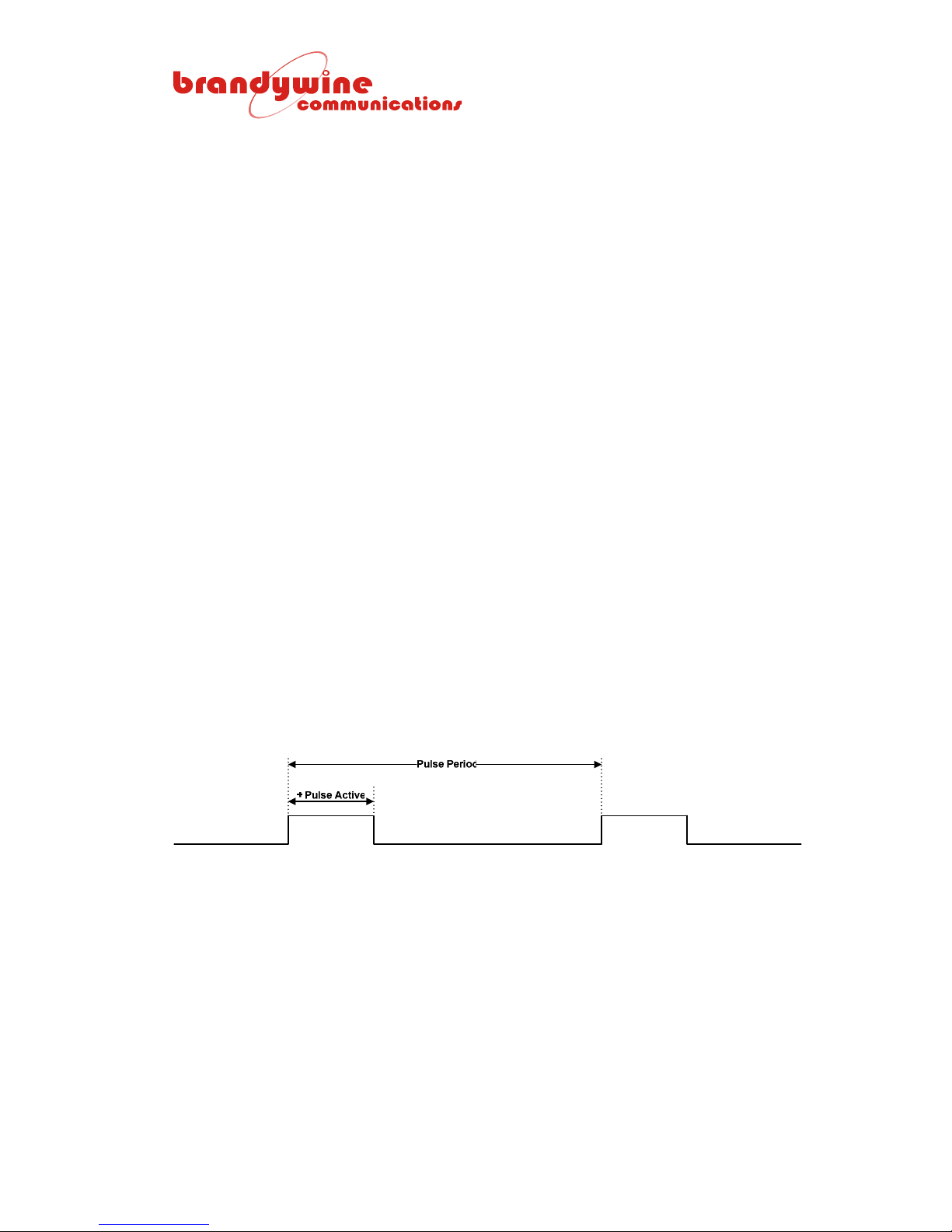
3.6.3.2 Examples of Pulse Periods
Note that the examples of the pulse periods are when the pulse periods are
specified instead of the UTC or local time. The pulse period may be a minimum
of 2 ms to a maximum of 9999 ms. The pulse width may be a minimum of 1 ms
to a maximum of 9998 ms. If the pulse length command asks for a length greater
than the period, it is automatically reset to 1 ms.
Illustration 2 Pulse Period
1. $PRCCG, C, P1000, +500*65<CR><LF>
The pulse output has a period of 1000 ms and is active high for 500 ms.
This is a square wave at 1 Hz. The positive edge commences at the
second’s edge. It will remain synchronized.
2. $PRCCG, C, P2, +1*52<CR><LF>
The pulse output has a period of 2 ms and is active high for 1 ms. This is
a square wave at 500 Hz. The positive edges will remain synchronized
with the seconds’ edges because the period of 2 ms is a sub-multiple of 1
second.
25
MANUAL P/N 900000007 REV 2.0
Page 26
3. $PRCCG, C, P2, -1*54<CR><LF>
The pulse output has a period of 2 ms and is active high for 1 ms. This is
a square wave at 500 Hz. The negative edges will remain synchronized
with the seconds’ edges because the period of 2 ms is a sub-multiple of 1
second and a negative pulse is specified.
4. $PRCCG, C, P9999, +9998*50<CR><LF>
The pulse period is 9999 ms and the pulse output is high for 9998 ms.
The output is high except for 1 ms at the end of the pulse. The period is
not a multiple of 1 Hz. The output goes high for the first time at the 1 Hz
edge following the receipt of the command. The next pulse starts 1 ms
before 10 seconds has elapsed. 9999 seconds must pass before the
pulse commences again at a second’s edge.
3.6.4 Dilution of Precision Values and Satellites Used
Requested by d<CR><LF>
Field 1 2 3 4 5 6 7 8 9 10 11...15 16 17
$GPGSA, A, 1, NN, NN, NN, NN, NN, NN, NN, NN,….,PP.PP, HH.HH, VV.VV*CK<CR><LF>
FIELD CONTENTS OF FIELD
1 “A” or “M” Operational mode:
“M” = 2-D mode only
“A” = 2-D/3-D auto-switching mode
2 “1” – “3” Positioning status:
“1” = positioning interrupted
“2” = 2-D positioning
“3” = 3-D positioning
3 – 14 NN Satellite numbers 01 – 32 used for positioning.
Note a null field is outputted unless a satellite is available.
15 PP.PP PDOP (combined DOP)
Note “00.00” is outputted unless 3-D positioning is performed.
16 HH.HH HDOP (horizontal DOP)
Note “00.00” is outputted while positioning is interrupted.
17 VV.VV VDOP (vertical DOP)
Note “00.00” is outputted unless 3-D positioning is performed.
3.6.4.1 Example Message
$GPGSA, A, 3, 03, 15, 17, 19, 21, 22, 23, 27,…,01.96, 01.05, 01.66*37<CR><LF>
26
MANUAL P/N 900000007 REV 2.0
Page 27
3.6.5 Time Code and Serial Dat a Out put Form a ts
Requested by e<CR><LF>
Sending the single letter ‘e’ followed by <CR><LF> requests a message from the
GPS8 Plus that describes its time code outputs and serial data formats. The
same message format transmitted to the GPS8 Plus can be used to set the time
code and serial data formats. The pulsed out put is report ed on ly. Use the ‘c’
command to define the pulsed output requirement in terms of UTC/local time
pulses or period defined pulses. In each case the pulse length is required.
Field 4 is reserved to allow future definition of different formats from TxD1. TxD1
is fixed as a serial type 2 requested time message.
Field 1 2 3 4 5
$PRCCG, E, X, X, X, X*CK<CR><LF>
FIELD CONTENTS OF FIELD
1 E Fixed letter “E” identifies the command
2
3
4 1 – 3 or X Reserved for TxD1 serial data format selection (not in use)
5
0 – 5 or X Time code 1 type
0 None – 1 KHz sine wave carrier at maximum level only
1 IRIG B – 1 KHz modulated carrier
2 XR3/2137 – 1 KHz modulated carrier
3 VELA – 1 KHz modulated carrier
4 NASA36 – 1 KHz modulated carrier
5 AFNOR – 1 KHz modulated carrier
X Do not change current output selection
0 – 3 or X Pulsed output type
0 None
1 Digital time code (0 to 5 V from 50R) as time code 1 above
2 UTC/local time defined pulse output – set by ‘c’ command only
3 Period defined multi-pulse output – set by ‘c’ command only
X Do not change current output selection
1 – 3 or X TxD2 automatic or requested serial data output format
selection (J12) see section 3.7
1 Type 1 format: 20:34:45 31/05/01 151 4
2 Type 2 format: 20:34:45.678 31/05/01 151 4
3 GPS4 format:
2001, 151:20:34:45, 3, 1
At power on, TxD2 automatically transmits the selected time message once per
second. On receipt of a lower case ‘t’ TxD1 outputs the time at which ‘t’ was
received in the currently selected format above and becomes a request port thus
only transmitting the time message on receipt of the ‘t’ from the user. The user
must send ‘r’ to the switch to turn on the automatic output of the time message
once per second.
27
MANUAL P/N 900000007 REV 2.0
Page 28

3.6.5.1 Example Messages
MESSAGE DESCRIPTION
$PRCCG, E, 1, 1, 1, 1*2C<CR><LF> -TC1 at J8 modulated time code output is IRIG B (1 KHz
carrier).
-TC2 at J10 pulse output is IRIG B (0 and 5 V from 50R).
-TxD1 at J12 is type 2 serial data request only (this
output is not currently changed by the command).
-TxD2 at J12 is type 1 format data, automatically output 1
per second until ‘t’ request when it becomes requested
only until ‘r’ is received. ‘t’ and ‘r’ do not require
<CR><LF> termination.
$PRCCG, E, 2, 1, 1, 1*2F<CR><LF> -TC1 at J8 modulated time code output is XR3/2137 (1
KHz carrier).
-TC2 at J10 pulse output is XR3/2137 (0 and 5 V from
50R).
-TxD1 at J12 is type 2 serial data request only (this
output is not currently changed by the command).
-TxD2 at J12 is type 1 format data, automatically output 1
per second until ‘t’ request when it becomes requested
only until ‘r’ is received. ‘t’ and ‘r’ do not require
<CR><LF> termination.
$PRCCG, E, 3, 1, 1, 1*2E<CR><LF> -TC1 at J8 modulated time code output is VELA (1 KHz
carrier).
-TC2 at J10 pulse output is VELA (0 and 5 V from 50R).
-TxD1 at J12 is type 2 serial data request only (this
output is not currently changed by the command).
-TxD2 at J12 is type 1 format data, automatically output 1
per second until ‘t’ request when it becomes requested
only until ‘r’ is received. ‘t’ and ‘r’ do not require
<CR><LF> termination.
$PRCCG, E, 4, 1, 1, 1*29<CR><LF -TC1 at J8 modulated time code output is NASA36 (1
KHz carrier).
-TC2 at J10 pulse output is NASA36 (0 and 5 V from
50R).
-TxD1 at J12 is type 2 serial data request only (this
output is not currently changed by the command).
-TxD2 at J12 is type 1 format data, automatically output 1
per second until ‘t’ request when it becomes requested
only until ‘r’ is received. ‘t’ and ‘r’ do not require
<CR><LF> termination.
$PRCCG, E, 1, 1, 1, 2*29<CR><LF> -TC1 at J8 modulated time code output is IRIG B (1 KHz
carrier).
-TC2 at J10 pulse output is IRIG B (0 and 5 V from 50R).
-TxD1 at J12 is type 2 serial data request only (this
output is not currently changed by the command).
-TxD2 at J12 is type 2 format data, automatically output 1
per second until ‘t’ request when it becomes requested
only until ‘r’ is received. ‘t’ and ‘r’ do not require
<CR><LF> termination.
28
MANUAL P/N 900000007 REV 2.0
Page 29

To change TC2 to a timed pulse output, the ‘c’ command must be used because
the specification of the pulse time or pulse period and pulse duration is required.
This example message $PRCCG, C, P2, +1*52<CR><LF>
makes TC2 output a 1 ms positive pulse with a 2 ms period (500 Hz and +ve
edge on time).
Send e<CR><LF> to query the output setup as seen in the example message
below:
MESSAGE DESCRIPTION
$PRCCG, E, 1, 3, 1, 2*2D -TC1 at J8 modulated time code output is IRIG B (1 KHz
carrier).
-TC2 at J10 pulse output is a pulse with period
specification.
-TxD1 at J12 is type 2 serial data request only (this
output is not currently changed by the command).
-TxD2 at J12 is type 2 format data, automatically output 1
per second until ‘t’ request when it becomes requested
only until ‘r’ is received. ‘t’ and ‘r’ do not require
<CR><LF> termination.
29
MANUAL P/N 900000007 REV 2.0
Page 30
3.6.6 Frequency and Phase Controller Data
Requested by f<CR><LF>
Field 1 2 3 4 5 6 7 8 9 10 11 12
$PRCCG, F, +XXX, +XXX, +XXX, +XXXXX, +X.XE-XX, +X.XXEXX, DDDHHMMSS, +XX.X, XX, XX, XX*CK<CR><LF>
The field lengths shown in the table below are typical, but not fixed (the leading
zeros and/or spaces are not necessarily transmitted).
FIELD CONTENTS OF
FIELD
1 F Fixed text “F” identifies the
message type
2 +XXX
3 +XXX Phase controller value (ns)
4 +XXX
5 +XXXXX
6 +X.XE-XX
7 +X.XXE-XX
8 DDD:HH:MM:SS
9 +XX.X Reserved for temperature in
10 XX
11 XX
12 XX Oscillator type (00 to FF) Fixed 2 ASCII hex chars
Instantaneous phase (ns)
(signed decimal integer)
(signed decimal integer)
Average phase (ns)
(signed decimal integer)
Frequency controller value
(signed decimal integer +0 =
nominal center)
Last frequency controller
correction
(decimal scientific notation)
Frequency trend
(decimal scientific notation)
UTC at last correc tio n (day of
year, hour, minute, and second)
degrees Celsius (not used in
GPS8 Plus controller, which
outputs +69.4)
Status of phase and
frequency controller (00 to
FF)
PLL constraint (TCSW) and
status
DESCRIPTION RANGE
ASCII ‘F’
–499999999
+500000000
Typical +0
2 chars to 10 chars
Will always be +0 in GPS8
Plus controller output
2 chars
–32768 to +32767
Minimum of 2 chars
Limited to 5 chars
Sign replaced by % if out of
range
–32768 to +32767
2 chars to 6 chars
1.0E-8 to 0.00E-14
7 chars to 9 chars
±1.0E-8 to ±0.00E-14
7 chars to 9 chars
Fixed 12 chars
+0.0 is 4 chars
+69.9 is 5 chars
Fixed 2 ASCII hex chars
Fixed 2 ASCII hex chars
3.6.6.1 Example Message
$PRCCG, F, -450, -382, +0, -2186, +3.0E-13, +1.14E-10, 144:09:54:00, +69.4, 60, 03, 03*3B<CR><LF>
30
MANUAL P/N 900000007 REV 2.0
Page 31

3.6.6.2 Instantaneous Phase
The instantaneous phase measurement between the 1 PPS recovered from the
satellite receiver and the 1 PPS generated by the internal precision oscillator is
reported in nanoseconds. The resolution of the measurement is 50 ns and the
maximum value is limited to ½ seconds (beyond this, the value is converted by
the calculation of the 1 second phase and the sign is reversed). A positive sign
always means the phase of the 1 PPS derived from the local oscillator and the
output to the user is ahead of the satellite receiver 1 PPS. Similarly a negative
sign means that the unit output 1 PPS is behind the satellite receiver 1 PPS.
The instantaneous phase value is outputted even when the satellite receiver 1
PPS signal is known to be invalid.
3.6.6.3 Average Phase
The average phase is the mean value of the instantaneous phase readings that
have been accepted. The resolution of this output is 1 ns. Occasionally the
instantaneous phase readings can be rejected by the GPS8 Plus (these readings
are not included in the average) for several reasons, such as the ones listed
below.
• Corrupt satellite data.
• Out of limit phase measurement.
• Excessive inaccuracy due to the re-introduction of selective availability
(SA).
3.6.6.4 Phase Controller Value
The phase controller value is the current value of the phase controller used to
adjust the local 1 PPS to UTC. In the GPS8 Plus this phase control is always set
to zero because following initialization the 1 PPS is maintained in phase with the
satellite 1 PPS by frequency control. If a large 1 PPS phase offset is detected for
any reason (e.g. after a long holdover period), values from 6 µs to 20 ms are
removed by phase stepping the output 1 PPS in 400 ns steps. An error larger
than 20 ms is corrected by resynchronization.
31
MANUAL P/N 900000007 REV 2.0
Page 32
3.6.6.5 Frequency Controller Value
The frequency controller value is the decimal value for the 16 bit DAC used for
controlling the frequency of the internal oscillator. The oscillator is initially factory
calibrated with a center control value, which is stored in EEPROM. This value is
transmitted to the DAC after switch on. As the oscillator gradually ages, this
value increases or decreases to maintain the correct output frequency. The
maximum range of the DAC is ±32767 counts, where a positive increase
indicates an increase in oscillator frequency.
At switch on the GPS8 Plus frequency control system starts with a fast time
constant to achieve frequency correction of the oscillator in the shortest possible
time. This process causes some rapid frequency changes while the oscillator is
coarsely adjusted via the DAC. When a sufficient measurement and control
history has been accumulated in memory and processed, a medium time
constant is implemented, which results in smaller and less frequent correction to
the local oscillator. Finally, after more extensive measurement and control data
has been stored and processed, the slow time constant is implemented, which
results in optimum frequency control strategy and hence accuracy of the internal
oscillator.
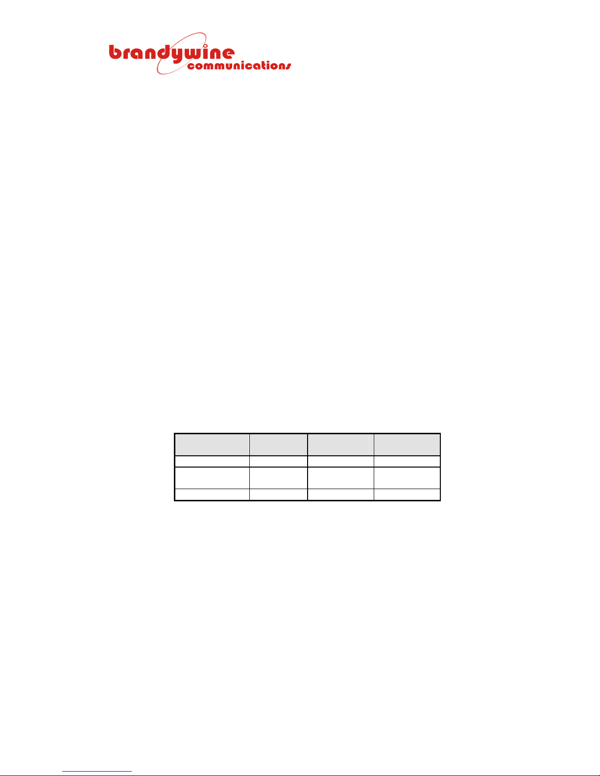
The time taken to change from FAST to MEDIUM to SLOW depends on several
parameters such as oscillator stability, satellite reception, and temperature
changes. Typical values are ½ hour to MEDIUM and 1.9 hours to SLOW for a
high stability crystal ovened oscillator. Typical values are 2.2 hours to MEDIUM
and 9 hours to SLOW for a standard rubidium oscillator.
OSCILLATOR
TYPE
OCXO 5 minutes 10 minutes 52 minutes
High Stability
OCXO
Rb_2 10 minutes 2.2 hours 9 hours
WARM UP
TIME
5 minutes 30 minutes 1.9 hours
Table 10 O scillator Changing Time
TIME IN
FAST
TIME IN
MEDIUM
3.6.6.6 Last Frequency Controller Correcti on
The last frequency controller correction is the value of the last frequency
correction applied by the 16 bit DAC. When the unit has found its average
position and the oscillator has overcome the high value of aging experienced in
the first few days after switch on, this value will usually be either zero or the
lowest possible frequency increment (e.g. 3E-13 for XTAL_1). The GPS8 Plus
controller algorithm works to keep each correction step magnitude below the
short term noise level of the oscillator type fitted, such that the action of
correction does not degrade the short term stability of the oscillator, which is
better than what can be recovered from the GPS.
32
MANUAL P/N 900000007 REV 2.0
Page 33
3.6.6.7 Frequency Trend
The frequency trend is the movement in the average phase over a specified
measurement period. The measurement period is dependent on the oscillator
option fitted and the time elapsed since start up. For example, a general purpose
ovened oscillator period starts at 1 second, after ten samples of 1 second the
period increases to 10 seconds, and after ten samples the period increases to
-
100 seconds, at which point the measurement resolution is 1 x 10
11
. The
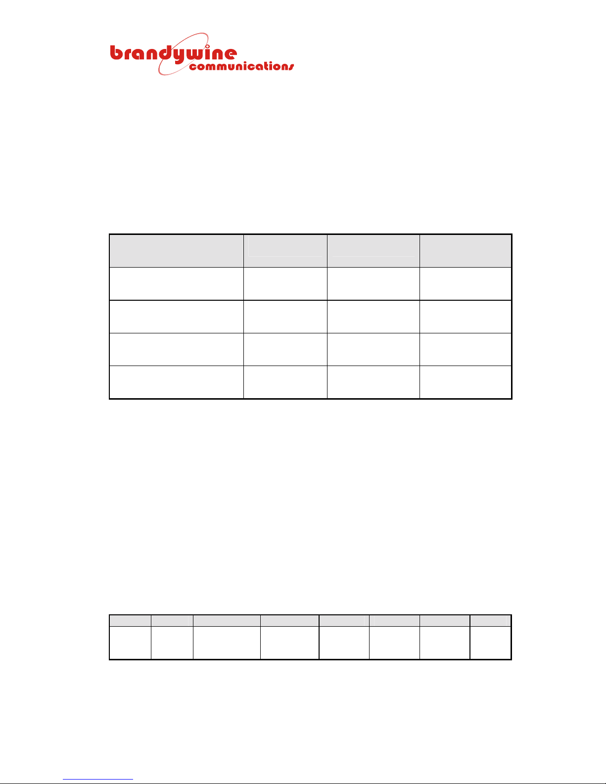
sample intervals and measurement periods for four oscillator options are shown
below.
OSCILLATOR TYPE SAMPLE
INTERVAL
TCXO 1 second 1 second
OCXO (XTAL_2)
High Stability OCXO
(XTAL_1)
Rubidium (Rb_2 & Rb_1)
Table 11 Oscillator Sample Intervals and Measurement Periods
1 second 1 second
10 seconds 10 seconds
100 seconds 100 seconds
MEASUREMENT
10 seconds
100 seconds
10 seconds
100 seconds
100 seconds
1000 seconds
1000 seconds
10000 seconds
PERIOD
FREQUENCY
MEASUREMENT
RESOLUTION
1E-9
1E-10
1E-11
1E-9
1E-10
1E-11
1E-10
1E-11
1E-12
1E-11
1E-12
1E-13
Phase readings are stored at every sample interval and the value transmitted is
updated at this point even when the measurement period is 1000 seconds. This
output gives the user a continuous and uninterrupted general indication of the
frequency accuracy of the internal disciplined oscillator.
3.6.6.8 UTC at Last Correction
The UTC at last correction is the time at which the last frequency controller
correction was applied.
3.6.6.9 Status of the Phase and Frequency Controller
Two ASCII hexadecimal characters indicate the status of the phase and
frequency controller, where bit 1 represents the described status below.
msb lsb msb lsb
PLL
limit
Reject
PLL
data
not time mark
Table 12 Phase and Frequency Controller Status
/TMV
valid
MANUAL P/N 900000007 REV 2.0
Reject
phase
(HW limit)
33
Reject
phase
(noise)
Rubidium
status
cold
Medium Slow
Page 34
3.6.6.10 PLL Constraint
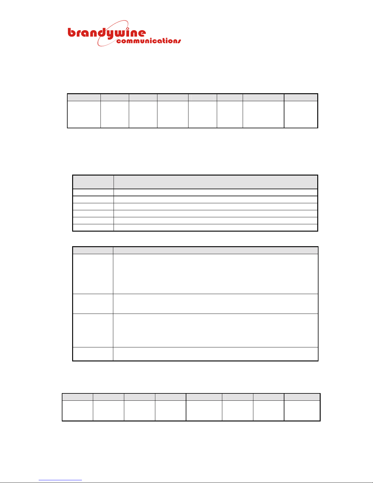
The PLL constraint consists of two ASCII hexadecimal characters that represent
4 bits of the status, where bit 1 represents the described status below.
msb lsb msb lsb
PLL
control
‘TCSW’
Bit 3
PLL
control
‘TCSW’
Bit 2
PLL
control
‘TCSW’
Bit 1
Table 13 PLL Constraint Status
PLL
control
‘TCSW’
Bit 0
Valid
time
RJ
code
Output or
synthesizer
fault
Frequency
control
fault
PLL control represents the user’s test command of a constraint called ‘TCSW’,
which has been applied to the frequency disciplining section. The values are
shown in the table below.
PLL Control
‘TCSW’
‘0’ No constraint and standard 3 time constant loop is running
‘1’ PLL is commanded to ‘FAST’ control only
‘2’ PLL loop is open with the EFC set for the center frequency
‘3’ PLL loop is open with the EFC frozen at its last setting
‘4’ PLL loop is open with the EFC set to maximum
‘5’ PLL loop is open with the EFC set to minimum
Table 14 TCSW Values
PLL Constraint
STATUS DESCRIPTION
Valid Time Set to 1 when the GPS8 Plus has synchronized to the satellite receiver. It is
reset to 0 if 8 hours elapsed without satellite reception or after the user reenters time from the keypad until the GPS 8000 has re-synchronized to the
GPS time. It is reset to 0 if 15 consecutive 1 PPS recovered time pulses are
outside the allocated phase limit. It is reset to 0 if a frequency error is
detected.
Reject Code Set to 1 at power-on and when satellite receiver time recovery data is marked
not valid, late, or inconsistent. During this condition the GPS8 Plus is
outputting back-up time not verified by comparison with the GPS data.
Output or
Synthesizer
Fault
Frequency
Control Fault
Set to 1 if any or up to 10 output failures have been detected or if the E1/T1
synthesizer is not locked. Each of the 10 outputs is monitored for amplitude
and a failure results in this bit being set. The associated indicator LED for the
output will be turned OFF. If the E1/T1 synthesizer is faulty, a red LED
indicator is turned ON in the main PCB.
Set to 1 if the frequency controller is unable to set the oscillator frequency to
track the reference frequency from the GPS receiver.
The oscillator type consists of two ASCII hexadecimal characters that represent 4
bits of the status, where bit 1 represents the described status below.
msb lsb msb lsb
Reserved Reserved Reserved Reserved Oscillator
type
Bit 3
Table 15 PLL Constraint Status
Oscillator
type
Bit 2
Oscillator
type
Bit 1
Oscillator
type
Bit 0
34
MANUAL P/N 900000007 REV 2.0
Page 35
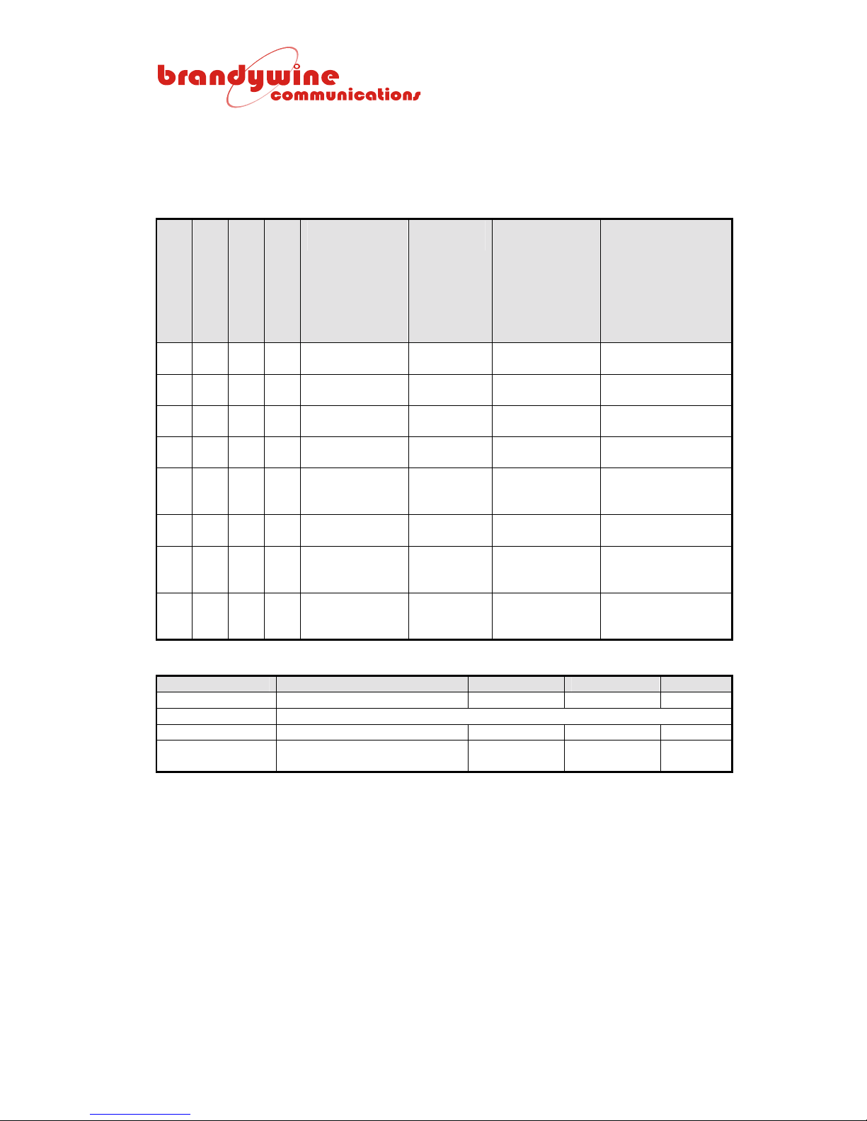
The oscillator type is determined by a jumper setting on the oscillator module and
additional option parameters stored in the EEPROM.
LK1 Link Setting: ‘1’ = jumper is fitted and ‘0’ link is open. In addition, the ‘5-6’
link is the nearest link to CON4 and the ‘1-2’ link is the nearest link to IC2.
5-6 3-4 1-2 NO OSCILLATOR
TYPE
0 0 0 00 Get oscillator
from EEPROM*
0 0 1 01 Standard
rubidium
0 1 0 02 High precision
OCXO (SC)
0 1 1 03 Low precision
OCXO (AT)
1 0 0 04 Standard
precision
OCXO (AT)
1 0 1 05 TCXO Positive OSA8410
1 1 0 06 TCXO with
poor 1 PPS
reference
1 1 1 07 MTI230-0501
with poor 1
PPS reference
Table 16 Oscillator Jumper Settings
CONTROL
SLOPE
Positive LPFRS 24 hours
Negative MTI 250-0502 12 hours
Positive HCD81 2 hours
Negative MTI 230-0501 2 hours
- - -
Negative MTI 230-0501 12 hours
EXAMPLE
OSCILLATOR
AV5H
MINIMUM TOTAL
DISCIPLINING
TIME BEFORE
CENTER
FREQUENCY IS
AUTOMATICALLY
SAVED IN THE
BLANK EEPROM
45 minutes
EEPROM CODE
00 High grade rubidium/CS Positive LPFRS opt A 48 hours
01 – 07 AS PER TABLE ABOVE FOR LINKS 001 – 111
08 Standard grade plain XTAL Positive
09 Brandywine High Stability
Positive 9 hours
OCXO (SC)
Table 17 EEPROM Code
35
MANUAL P/N 900000007 REV 2.0
Page 36
3.6.7 Health Status of Satellites
Requested by h<CR><LF>
Field 1 2 3
$PFEC, GPanc, YYMMDDhhmmss, XXXXXXXXXXXXXXXXXXXXXXXXXXXXXXXX*CK<CR><LF>
FIELD CONTENTS OF FIELD
1 GPanc
2 YYMMDDhhmmss
3
X
“0”
“1” Unhealthy (not used for positioning or timing)
“2” Healthy (used for positioning and timing)
Fixed text identifier
Almanac date/time
Where YY = year, MM = month, DD = day, hh = hour, mm =
minute, and ss = seconds
32 columns being the status of satellite PRN 1 – 32, where the
status is as follows:
Almanac not collected yet or satellite is not launched yet
3.6.7.1 Example Response
Field 1 2 3
$PFEC, GPanc, 990524095412, 22222222220022222220222222202220*4D<CR><LF>
36
MANUAL P/N 900000007 REV 2.0
Page 37
3.6.8 Leap Second Information (Firmware 13+)
Requested by j<CR><LF>
Field 1 2 3 4
$PRCCG, J, YYMMDDhhmmss, +1, dd*CK<CR><LF>
FIELD CONTENTS OF FIELD
1 J Fixed text identifier “J”
2
3
YYMMDDhhmmss Leap second date
Where YY = year, MM = month, DD = day, hh = hour, mm =
minute, and ss = second
000000000000
+1 Leap second is to be inserted at the leap second date.
–1 Leap second is to be deleted at the leap second date.
00 Leap second date has passed or the parameter is not yet
SS GPS-UTC seconds offset. 4
00 The GPS-UTC value has not yet been acquired. This field
The leap second date information has not been acquired.
Usually a GPS satellite announces the date, time, and value
for a leap second adjustment repeatedly for two to six
months before the adjustment is actually executed. After the
adjustment has been made the announcement is continued
for some period of time. In this period of post-execution
announcement, if the pre-execution announcement was not
received, the leap second field 3 below is filled with 00
because it is no longer available from the satellites.
available.
accumulates leap seconds since the GPS system started
operation on January 6, 1980. As of April 2001 this value is
13.
3.6.8.1 Example Response
Field 1 2 3 4
$PRCCG, J, 9901010000, +1, 13*CK<CR><LF>
37
MANUAL P/N 900000007 REV 2.0
Page 38

3.6.9 2
nd
Pulse Output Data and Command (PCB CON6 Pin 3)
Requested by k<CR><LF>
Note that units using this pulse output are specified by specific part numbers.
A second pulse output is available internally at CON6 pin 3 and may be
optionally routed to the user as a second pulse output. Sending the single letter
‘k’ followed by <CR><LF> requests a message from the GPS8 Plus that
describes its 2
nd
pulse output from CON6 pin 3. The same message format
transmitted to the GPS8 Plus sets the pulse output parameters, which are stored
in non-volatile RAM. The pulse output (CMOS logic levels at 0 V and 5 V
internally) can be commanded to be normally low going high for the pulse
duration or normally high going low for the pulse duration. There are two ways to
specify the pulse occurrence and duration. Unlike the 1
st
pulse output, this
output cannot be normally commanded to be a time code.
1. The 2
nd
pulse output can be specified to occur at the UTC or local time. In
this case, the 2
nd
pulse outputs always start at the second’s edge (UTC to
within ±150 ns) and terminate at a specified number of milliseconds later.
The ‘don’t care’ characters in the pulse time definition allow hour, minute,
or second values to be ignored. The default 2
nd
pulse output setting is 1
PPM, a positive pulse, and 100 ms long. The minimum pulse duration is 1
ms and the maximum pulse duration is 9999 ms.
2. Alternatively, the 2
nd
pulse output can be defined in terms of the period of
the pulse stream together with the pulse active duration. The minimum
period is 2 ms and the maximum period is 9999 ms. The minimum pulse
length is 1 ms and the maximum pulse length is 1 ms less than the period.
Immediately after receipt of the command the current pulse (if active) is
terminated and the first new pulse commences at the start of the next
second’s edge. If the pulse period (specified in milliseconds) is a submultiple or a multiple of the seconds, the pulses remain synchronized with
1 PPS. If the contrary is true, the pulses may require multiple seconds
before the start of a pulse coincides with 1 PPS. However, they are
always strictly related to real-time milliseconds as long as the unit is
locked to the GPS.
Remember that if the checksum is omitted in the user command to the GPS8
Plus, the ‘*’ must be omitted from the end of the message so that the GPS8 Plus
recognizes that no checksum is available. Two forms exist as seen below:
• Form 1 (2
nd
pulse output at specified time, UTC or local):
Field 1 2 3
$PRCCG, K, UHHMMSS, +9999*CK<CR><LF>
nd
• Form 2 (2
pulse output with specified period):
Field 1 2 3
$PRCCG, K, P9999, +9998*50<CR><LF>
38
MANUAL P/N 900000007 REV 2.0
Page 39
Refer to the ‘c’ command description above for more pulse command examples.
The ‘c’ command is almost identical to the ‘k’ command except the ‘c’ command
specifies the 1
‘c’ for the 2
st
pulse output instead of the 2nd pulse output. Since ‘k’ replaces
nd
pulse output, any checksum examples given for the ‘c’ command is
different for the ‘k’ command.
3.6.10 Location and Signal Noise Ratio of Satellites
Requested by l<CR><LF>
The response to the ‘l’ request contains a maximum of three records.
Field 1 2 3 4 5 6 7 8 9 10 11 12 13 14 15 16 17 18 19
$GPGSV, N, n, NN, SS, XX, XXX, XX, SS, XX, XXX, XX, SS, XX, XXX, XX, SS, XX, XXX, XX*CK<CR><LF>
FIELD CONTENTS OF FIELD
1 N Total number of messages (1 – 3)
2 n Number of this message
3 NN Number of satellites in line-of-site (with elevation > 5 degrees
only) (00 – 12)
4 SS 1st satellite PRN
5 XX 1st satellite elevation (degrees 05 – 90)
6 XXX 1st satellite azimuth (degrees 000 – 359)
7 XX 1st satellite signal-noise-ratio (dB Hz 00 – 99)
8 – 11 2nd satellite details
12 – 15 3rd satellite details
16 – 19 4th satellite details
3.6.10.1 Example Messages
$GPGSV, 2, 1, 07, 03, 41, 270, 51, 06, 18, 083, 33, 17, 64, 083, 49, 19, 09, 329, 45*74
$GPGSV, 2, 2, 07, 22, 74, 208, 48, 23, 21, 126, 45, 25, 06, 195, 39*4B
ABBREVIATION DESCRIPTION
PRN Shows the unique identification number of the satellite from 1 – 32.
ELV Shows the elevation of each satellite in degrees.
AZ Shows the azimuth of each satellite in degrees.
S/N Shows the signal to noise ratio of each satellite in dB. Below 40 is poor, 40 –
46 is average, and above 46 is good. The signal to noise ratio is a relative
value for a single receiver and may not be the same for any two receivers
operating in identical conditions.
39
MANUAL P/N 900000007 REV 2.0
Page 40
3.6.11 Firmware Version Number
Requested by n<CR><LF>
The software version number is only outputted.
Field 1 2 3 4
$PRCCG, N, nnn, ppppppp-vvv, t*CK<CR><LF>
FIELD CONTENTS OF FIELD
1 Fixed text letter “N”
2 3 digit decimal firmware serial number with leading zeros included
3 7 digit engine program and 3 digit version number
4 Test result
If the firmware version is EGPS13 and the engine is 4850102 version 009, the
example message will be $PRCCG, N, 013, 4850102-009, 1*CK<CR><LF>.
The firmware resides in both flash memory and EPROM. If the flash memory
has been reprogrammed, the current version may be a higher number than the
number written by the label on EPROM. It is possible to revert to EPROM
firmware by fitting the jumper at LK1. If flash me mory is to be repr o gra mmed,
LK1 must be open.
40
MANUAL P/N 900000007 REV 2.0
Page 41
3.6.12 Offset of Local Time Data and Command
Requested by o<CR><LF>
The local time parameters listed below are reported by the GPS8 Plus in
response to the single character o<CR><LF> request. The same format is used
in a user command transmitted to the GPS8 Plus to set the local time
parameters, which are stored in non-volatile RAM. The message format must be
entered exactly as shown below, including the colon and dummy data for the
minute offset (not used). Remember that if the checksum is omitted, the ‘* ’ must
be omitted from the end of the message so that the GPS8 Plus recognizes that
no checksum is available.
Note that the pulse output time (refer to the ‘c’ response and associated
command) has its own local time/UTC switch, which is independent of the ‘o’
command local time/UTC switch for time and time code outputs. However, the
sign and number of the hour offset of the local time is programmed by the ‘o’
command alone. The user can set the GPS8 Plus time code output to UTC, but
it generates pulse outputs which follow local time.
Field 1 2 3
$PRCCG, O, U, +HH:00*CK<CR><LF>
FIELD CONTENTS OF FIELD
1 Fixed text letter “O”
2 ‘U’ = time and time code outputs are UTC.
‘L’ = time and time code outputs are local time.
3 ‘+’ = adds the following hour offset to UTC to obtain the local time.
‘–’ = subtracts the following hour offset from UTC to obtain the local time.
HH = number of hour offset (must have leading zero if < 10 hours or two zeros if
the value is zero). The maximum offset is + or – 23 hours.
:00 = hour and minute separator and data reserved for minute offset.
3.6.12.1 Example Commands
1. $PRCCG, O, L, +01:00*7A<CR><LF>
The time code output and the time returned in response to the ‘t’ time
request is local time. The local time is the UTC time added with an hour.
The count offset time rolls over through days to years if required.
2. $PRCCG, O, L, -23:00*7C<CR><LF>
The time code output and the time returned in response to the ‘t’ time
request is local time. The local time is the UTC time subtracted with 23
hours. The count offset time borrows from days through to years if
required.
When a command has been accepted by the GPS8 Plus the message is
echoed, but the contents of the response are recalculated from the data
used by the GPS8 Plus to implement the user request. A checksum is
always returned.
41
MANUAL P/N 900000007 REV 2.0
Page 42
3.6.13 Position of GPS Antenna
Requested by p<CR><LF>
Field 1 2 3 4 5 6 7 8 9 10 11 12 13 14
$GPGGA, hhmmss, DDMM.MMMM, N, DDDMM.DDDD, E, s, NN, 00.00, AAAAAA.A, M, GGGG.G, M,.,*CK<CR><LF>
FIELD CONTENTS OF FIELD
1 hhmmss Time (UTC) of position update
2 DDMM.MMMM Latitude (degrees, minutes, and decimal fraction of minutes)
3 N “N” = north and “S” = south
4 DDDMM.MMMM Longitude
5 W “W” = west and “E” = east
6 Status “0” = positioning not operational (or known position)
“1” = positioning operational
“2” = differential positioning
7 NN Number of satellites used for positioning
8 DOP DOP (2D: HDOP, 3D: PDOP)
9 Altitude AAAAAA.A (– 00999.9 to 017999.9)
10 M Unit for altitude (M = meters)
11 GGGG.G Geoid altitude (– 999.9 to 9999.9)
12 M Unit for Geoid altitude (M = meters)
13 Null field Reserved for DGPS data (time elapsed since last RTCM-
SC104 data updating)
14 Null field Reserved for DGPS station identification
3.6.13.1 Example Response
$GPGGA, 095427, 5147.1358, N, 00049.8371, E, 1, 06, 01.71, 000026.0, M, 0046.3, M,.,*73
42
MANUAL P/N 900000007 REV 2.0
Page 43
3.6.14 Additional Information (Including Magnetic Declination)
Requested by s<CR><LF>
Field 1 2 3 4 5 6 7 8 9 10 11
$GPRMC, hhmmss, A, DDMM.MMMM, N, DDDMM.DDDD, E ,000.0, 000.0, DDMMYY, MMM.M, W*CK<CR><LF>
FIELD CONTENTS OF FIELD
1 hhmmss Time (UTC) of position update
2 A or V A = positioning
V = positioning interrupted or known position
3 DDMM.MMMM Latitude (degrees, minutes, and decimal fraction of minutes)
4 N “N” = north and “S” = south
5 DDDMM.MMMM Longitude (degrees, minutes, and decimal fraction of
minutes)
6 W “W” = west and “E” = east
7 Speed Speed in knots (000.0 to 999.9)
8 True course True course in degrees (000.0 to 359.9)
9 DDMMYY UTC date as day, month, and year (1994 to 2040)
10 MMM.M Magnetic deviation in degrees (000.0 to 180.0)
11 W “W” (MAG = TRUE – DEV) or “E” (MAG = TRUE + DEV)
3.6.14.1 Example Response
$GPRMC, 095431, A, 5147.1362, N, 00049.8371, E, 000.3, 005.7, 240599, 003.1, W*6F
3.6.15 Request Precision Time
Requested by t<CR><LF>
The purpose of this request is to capture time for data logging, time tagging, and
etcetera. This message takes priority over other messages which will be
inhibited while ‘t’ is active. If a message is already being transmitted, use of the
‘t’ request may cause a disjointed message when the high priority output is
immediately transmitted. The time in the message reflects the instance the stop
bit of ‘t’ was received and advanced by 1 ms to compensate for the typical
character delay. If the serial port is busy when a request is received, it will be
ignored. Maximum request rate will depend on the baud rate. For example, at
4800 baud the serial port can transmit about ten messages per second. The
format of the message is type 2 (refer to section 3.7).
43
MANUAL P/N 900000007 REV 2.0
Page 44

3.6.16 Software Reset Command
The unit can be reset by an NMEA style command such as the one seen below:
$PRCCG, Z, 0*2F<CR><LF>
It is not necessary (but highly recommended) that the checksum be included at
the end of this message. The value is always ‘2F’ since the content of the
command is fixed. The message must contain the correct header, the correct
number of characters, the ‘Z’, the ‘0’, and the correct checksum. The ‘0’ refers to
the number zero (ASCII code 30 hexadecimal) and describes the type of reset to
use. If the message corresponds correctly to the reset command and the
checksum is valid, the GPS8 Plus returns the message as an acknowledgment
and waits 160 ms and then restarts the initialization as though the unit had just
been switched on. The initialization messages are outputted as each stage is
completed. Note that there is a pause of about 5 seconds after the reset (a
decimal point is outputted as each second passes) in which the download of new
firmware to the GPS8 Plus flash memory could be initiated.
44
MANUAL P/N 900000007 REV 2.0
Page 45
3.7 TxD2/RxD2 Messages (Rear Panel J12)
The GPS8 Plus second serial output is configured to output serial data in the
user’s chosen format automatically after initialization. The format selection can
be changed by entering a simple command into the TxD1/RxD1 command port at
J13. Three formats are discussed below. Other customer specific outputs and
protocols are available. The baud rate and character format are fixed as
described above (4800, 8, N, and 1). To request data from the port, the user
sends the character ‘t’ to request time. The port sends the message, reporting
the time at which ‘t’ was received and the automatic 1 per second output stops.
No further output is transmitted until another request ‘t’ is received. To restore
the automatic 1 per second output, the user must send ‘r’ to the port.
3.7.1 Type 1 Format
Field 1 2 3 4
HH:MM:SS DD/MN/YY NNN W<CR><LF>
FIELD CONTENTS OF FIELD
1 Hours, minutes, and seconds (UTC)
2 Day of month, month, and year
3 Day of year (January 1 = 001)
4 Day of week (Monday = 1 and Sunday = 7)
3.7.1.1 Example Message
The example message has a fixed format of 25 characters, including spaces and
termination.
20:34:03 08/11/91 312 5<CR><LF>
3.7.2 Type 2 Format
Field 1 2 3 4 5
HH:MM:SS.SSS DD/MN/YY NNN W S<CR><LF>
FIELD CONTENTS OF FIELD
1 Hours, minutes, and seconds (UTC)
2 Day of month, month, and year
3 Day of year (January 1 = 001)
4 Day of week (Monday = 1 and Sunday = 7)
5 Status
45
MANUAL P/N 900000007 REV 2.0
Page 46
The status character is an ASCII representation of the hexadecimal figure from 0
to F (refer to section 3.3) where the bits are allocated as follows:
BIT 3 (MSB) BIT 2 BIT 1 BIT 0 (LSB)
Valid time Reject code Local time Leap year
Table 18 Status Bit Allocation
• Valid time is set to 1 when the GPS8 Plus has synchronized to the satellite
receiver. It is reset to 0 if 8 hours elapsed without satellite reception or
after the user re-enters time from the keypad until the GPS 8000 has resynchronized to the GPS time. It is reset to 0 if 15 consecutive 1 PPS
recovered time pulses are outside the allocated phase limit. It is reset to 0
if a frequency error is detected.
• Reject code is set to 1 at power on and when the satellite receiver time
recovery data is marked not valid, is late, or inconsistent. During this
condition the GPS8 Plus is outputting back up time not verified by
comparison with the GPS data. It is quite normal for the occasional
‘Reject Data’ indicator to illuminate.
• Local time is set to 1 for local time and reset to 0 for UTC time.
• Leap year is a year divisible by 4, including the century if it is also divisible
by 4 (e.g. 2000 but not 2100).
3.7.2.1 Example Message
The example message has a fixed format of 31 characters, including spaces.
The example below means a request was made at thirty four minutes, three
seconds, and 123 milliseconds past eight in the evening on Tuesday the 15
th
of
March 1988 with the GPS synchronized master clock reporting valid time, GPS
locked, and UTC in a leap year.
20:34:03.123 17/03/88 077 2 9<CR><LF>
The character ‘9’ status is described in the table below:
BIT 3 (MSB) BIT 2 BIT 1 BIT 0 (L SB)
1 0 0 1
Valid time Synchronized
last second
(no reject
code)
Table 19 Character ‘9’ Status
UTC Year is a leap
year
The second port responds identically to TxD1/RxD1. Both ports can be polled
rapidly and asynchronously to report the time to independent users.
46
MANUAL P/N 900000007 REV 2.0
Page 47
3.7.3 Type 3 Format (GPS4 Format)
Field 1 2 3 4
YYYY, DDD:HH:MM:SS, T, S<CR><LF>
FIELD CONTENTS OF FIELD
1 Year (UTC)
2 Day of year (January 1 = 001), hours, minutes, and seconds
3 TFOM
4 Status of time
Please note that TFOM refers to Time Figur e of Merit and S r efers to Status.
TFOM DESCRIPTION
9 10 ms < PPS
8 1 ms < PPS ≤10 ms
7 100 µs < PPS ≤ 1 ms
6 10 µs < PPS ≤ 100 µs
5 1 µs < PPS ≤ 100 ns
4 100 ns < PPS ≤ 1 µs
3 PPS ≤ 100 ns
Table 20 TFOM Values
Status S DESCRIPTION
0 Coasting
1 Time locked
2 Holdover
3 Recovery
4 Power-up
Table 21 Status Values
3.7.3.1 Example Message
The example message has a fixed format of 23 characters, including commas
and termination.
2001, 156:15:17:43, 3, 1<CR><LF>
47
MANUAL P/N 900000007 REV 2.0
Page 48

3.8 IRIG B and AFNOR NF 2 87-500 Time Code Output
IRIG B and AFNOR NF 2 87-500 time code is the generated standard by the
GPS8 Plus. This time code consists of a 1 KHz carrier, which is modulated in the
pattern described below. The carrier and time code is synchronized precisely to
the GPS time by the GPS8 Plus. To select the desired time code, use the NMEA
style ‘e’ command described in section 3.6.5. The type of code in operation is
queried by sending e<CR><LF> to the command port.
FORMAT DESCRIPTION
Time Universal Time (UTC)
Time frame 1.0 second
Code digit weighting BCD and SB as follows:
a Binary Coded Decimal time-of-year code word: 30 binary digits.
(1) Seconds, minutes, hours, and days.
(2) Recycles yearly.
b Straight Binary time-of-day code word: 17 binary digits.
(1) Seconds only.
(2) Recycles every 24 hours.
a BCD: word begins at index count 1. Binary coded elements occur
between the position identifier elements (7 for seconds, 7 for minutes, 6
for hours, 8 and 2 for days) until the code word is complete. An index
marker occurs between the decimal digits in each group to provide
separation for visual resolution.
b SB: word begins at index count 80. Five decimal digits (17 binary
coded elements) occur with a position identifier between the 9
binary coded elements.
Bit order Least significant digit occurs first.
Element rate 100 per second
Element identification
a On time reference point for all elements is the leading edge.
b Index marker: 2 ms
(Binary zero or un-coded element)
c Code digit : 5 ms
d Position identifier - 10 per second: 8 ms
(Refers to the leading edge of the succeeding element)
e Reference marker - 1 per second: Two consecutive position identifiers.
Table 22 IRIG B Format Specificatio n
The ‘on time’ point to which the code word refers to is the leading edge of the
second position identifier.
• Resolution: 10 ms (un-modulated) or 1 ms (modulated)
• Carrier frequency: 1 KHz (modulated)
th
and 10th
48
MANUAL P/N 900000007 REV 2.0
Page 49
3.8.1 IRIG B and AFNOR NF 2 87-500 Time Code Bit Allocation
Each time code bit has 10 ms of duration therefore it contains 10 cycles of the 1
KHz carrier. In the table below ‘0’ is 2 ms higher level duration, ‘1’ is 5 ms higher
level duration, and ‘Marker’ is 8 ms higher level duration. The standard output
level for the higher level carrier (AFNOR specification) is 0 dB into 600R (2.17
V
pp
± 10%). The lower level is ⅓ of the higher level or the higher level - 10 dB.
There are 100 bits total in one second with bit 0 (an 8 ms marker) starting at the
second’s edge. The GPS8 Plus allows the selection of IRIG B time code without
the AFNOR extensions (TC1 = 1 in the ‘e’ command) or with AFNOR (TC1 = 5 in
the ‘e’ command). If IRIG B is selected, the control bits are set to ‘0’.
BIT WEIGHT CODE BIT WEIGHT CODE
00 Marker Pr IRIG B 50 Year 1 AFNOR
01 Seconds 1 IRIG B 51 Year 2 AFNOR
02 Seconds 2 IRIG B 52 Year 3 AFNOR
03 Seconds 4 IRIG B 53 Year 4 AFNOR
04 Seconds 8 IRIG B 54 Always 0 IRIG B
05 Always 0 IRIG B 55 Year 10 AFNOR
06 Seconds 10 IRIG B 56 Year 20 AFNOR
07 Seconds 20 IRIG B 57 Year 40 AFNOR
08 Seconds 40 IRIG B 58 Year 80 AFNOR
09 Marker P1 IRIG B 59 Marker P6 IRIG B
10 Minutes 1 IRIG B 60 Month 1 AFNOR
11 Minutes 2 IRIG B 61 Month 2 AFNOR
12 Minutes 4 IRIG B 62 Month 4 AFNOR
13 Minutes 8 IRIG B 63 Month 8 AFNOR
14 Always 0 IRIG B 64 Always 0 IRIG B
15 Minutes 10 IRIG B 65 Month 10 AFNOR
16 Minutes 20 IRIG B 66 Always 0 AFNOR
17 Minutes 40 IRIG B 67 Always 0 AFNOR
18 Always 0 IRIG B 68 Always 0 IRIG B
19 Marker P2 IRIG B 69 Marker P7 IRIG B
20 Hours 1 IRIG B 70 Day of month 1 AFNOR
21 Hours 2 IRIG B 71 Day of month 2 AFNOR
22 Hours 4 IRIG B 72 Day of month 4 AFNOR
23 Hours 8 IRIG B 73 Day of month 8 AFNOR
24 Always 0 IRIG B 74 Always 0 AFNOR
25 Hours 10 IRIG B 75 Day of month 10 AFNOR
26 Hours 20 IRIG B 76 Day of month 20 AFNOR
27 Always 0 IRIG B 77 Always 0 IRIG B
28 Always 0 IRIG B 78 Always 0 IRIG B
29 Marker P3 IRIG B 79 Marker P8 IRIG B
30 Day of year 1 IRIG B 80 Counter clock 2^0 IRIG B
31 Day of year 2 IRIG B 81 Counter clock 2^1 IRIG B
32 Day of year 4 IRIG B 82 Counter clock 2^2 IRIG B
33 Day of year 8 IRIG B 83 Counter clock 2^3 IRIG B
34 Always 0 IRIG B 84 Counter clock 2^4 IRIG B
35 Day of year 10 IRIG B 85 Counter clock 2^5 IRIG B
36 Day of year 20 IRIG B 86 Counter clock 2^6 IRIG B
37 Day of year 40 IRIG B 87 Counter clock 2^7 IRIG B
38 Day of year 80 IRIG B 88 Counter clock 2^8 IRIG B
39 Marker P4 IRIG B 89 Marker P9 IRIG B
40 Day of year 100 IRIG B 90 Counter clock 2^9 IRIG B
41 Day of year 200 IRIG B 91 Counter clock 2^10 IRIG B
42 Always 0 IRIG B 92 Counter clock 2^11 IRIG B
43 Always 0 IRIG B 93 Counter clock 2^12 IRIG B
44 Day of week 1 AFNOR 94 Counter clock 2^13 IRIG B
45 Day of week 2 AFNOR 95 Counter clock 2^14 IRIG B
46 Day of week 4 AFNOR 96 Counter clock 2^15 IRIG B
47 Always 0 IRIG B 97 Counter clock 2^16 IRIG B
48 Always 0 IRIG B 98 Counter clock 2^17 IRIG B
49 Marker P5 IRIG B 99 Marker P0 IRIG B
49
MANUAL P/N 900000007 REV 2.0
Page 50
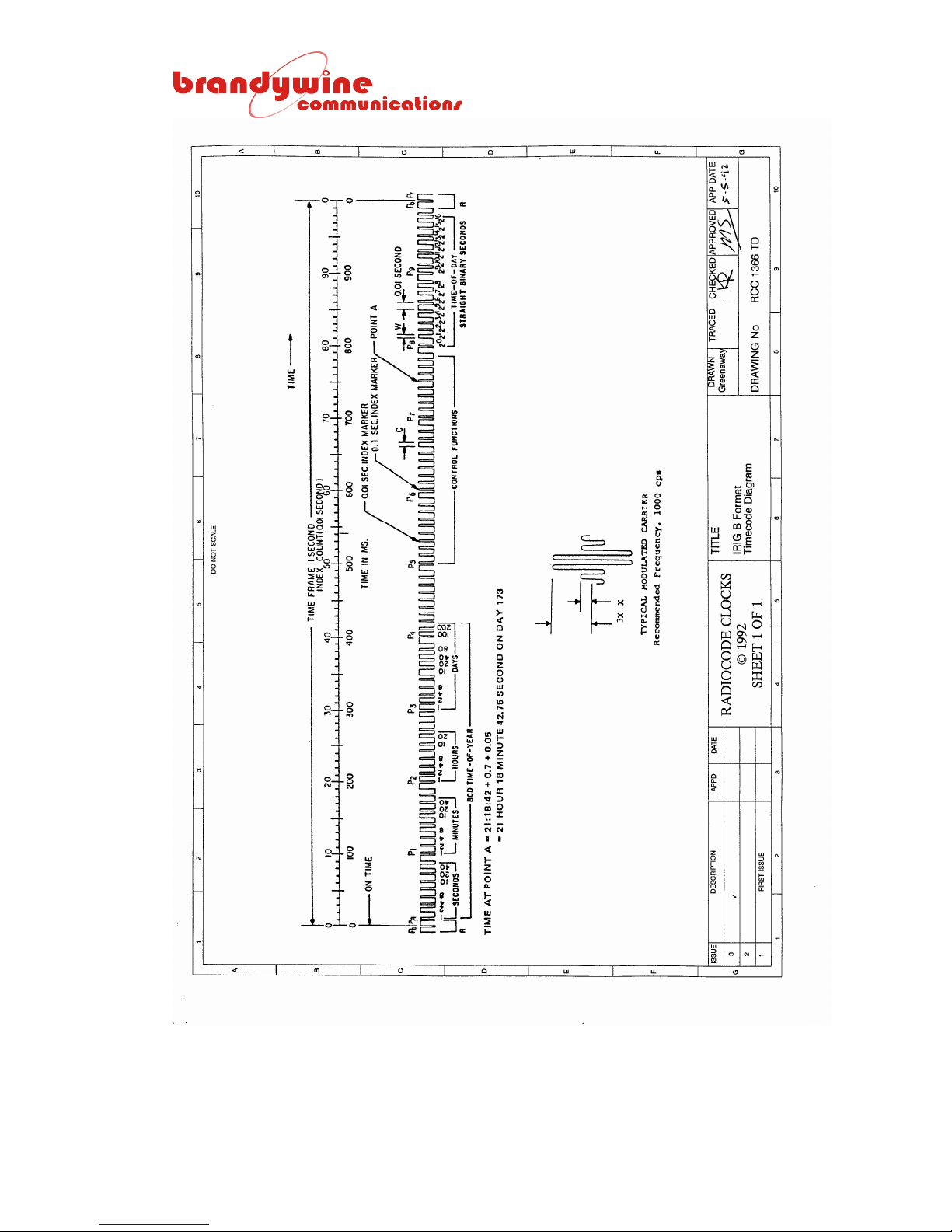
50
MANUAL P/N 900000007 REV 2.0
Page 51

3.9 NASA36 Time Code Output
NASA36 time code can be selected by the user using the ‘e’ command. NASA36
time code operates in a similar manner to IRIG B with the bit allocations
described below. 1 KHz is the standard carrier for NASA36 time code. To
select the desired time code, use the NMEA style ‘e’ command described in
section 3.6.5. The type of code in operation is queried by sending e<CR><LF>
to the command port.
FORMAT DESCRIPTION
Time Universal Time (UTC) or local time
Time frame 1.0 second
Code digit weighting BCD as follows:
a Binary Coded Decimal time-of-year code word: 30 binary digits.
(1) Seconds, minutes, hours, and days.
(2) Recycles yearly.
Word begins at index count 1. Binary coded elements occur between
the position identifier elements 600 ms duration every 100 ms from 100
ms to 900 ms inclusive.
Bit order Least significant digit occurs first.
Element rate 100 per second
Element identification
a On time reference point for all elements is the leading edge.
b Index marker: 2 ms
(Binary zero or un-coded element)
c Code digit : 6 ms
(Binary one)
d Position identifier - 9 per second: 6 ms
(Refers to the leading edge of the succeeding element)
e Reference marker - 1 per second: Five consecutive position identifiers,
followed by a zero
Resolution 10 ms (un-modulated)
1 ms (modulated)
Carrier frequency 1 KHz when modulated
Table 23 NASA36 Format Specification
51
MANUAL P/N 900000007 REV 2.0
Page 52
BIT WEIGHT BIT WEIGHT
00 Reference always 0 50 Position identifier
01 Seconds 1 51 Hours 10
02 Seconds 2 52 Hours 20
03 Seconds 4 53 Always 0
04 Seconds 8 54 Always 0
05 Always 0 55 Always 0
06 Always 0 56 Always 0
07 Always 0 57 Always 0
08 Always 0 58 Always 0
09 Always 0 59 Always 0
10 Marker 60 Position identifier
11 Seconds 10 61 Day of year 1
12 Seconds 20 62 Day of year 2
13 Seconds 40 63 Day of year 4
14 Always 0 64 Day of year 8
15 Always 0 65 Always 0
16 Always 0 66 Always 0
17 Always 0 67 Always 0
18 Always 0 68 Always 0
19 Always 0 69 Always 0
20 Position identifier 70 Position identifier
21 Minutes 1 71 Day of year 10
22 Minutes 2 72 Day of year 20
23 Minutes 4 73 Day of year 40
24 Minutes 8 74 Day of year 80
25 Always 0 75 Always 0
26 Always 0 76 Always 0
27 Always 0 77 Always 0
28 Always 0 78 Always 0
29 Always 0 79 Always 0
30 Position identifier 80 Position identifier
31 Minutes 10 81 Day of year 100
32 Minutes 20 82 Day of year 200
33 Minutes 40 83 Day of year 400
34 Always 0 84 Day of year 800
35 Always 0 85 Always 0
36 Always 0 86 Always 0
37 Always 0 87 Always 0
38 Always 0 88 Always 0
39 Always 0 89 Always 0
40 Position identifier 90 Position identifier
41 Hours 1 91 Control functions
42 Hours 2 92 Control functions
43 Hours 4 93 Control functions
44 Hours 8 94 Control functions
45 Always 0 95 Position identifier
46 Always 0 96 Position identifier
47 Always 0 97 Position identifier
48 Always 0 98 Position identifier
49 Always 0 99 Position identifier
Table 24 NASA36 Bit Allocation
52
MANUAL P/N 900000007 REV 2.0
Page 53

3.10 2137 Time Code Output
The 2137 time code can be selected by the user. 1 KHz is the standard carrier
frequency for 2137, which otherwise resembles the code known as XR3. To
select the desired time code, use the NMEA style ‘e’ command described in
section 3.6.5. The type of code in operation is queried by sending e<CR><LF>
to the command port.
FORMAT DESCRIPTION
Time Universal Time (UTC)
Time frame 1.0 second
Code digit weighting BCD
Binary Coded Decimal time-of-day code word: 20 binary digits.
Hours, minutes, and seconds. Recycles every 24 hours.
Code word structure Word begins during the first 40 ms index count of the current time
frame. Binary coded elements occur every 40 ms during the current
time frame (6 for hours, 7 for minutes, and 7 for seconds) until the code
word is complete. A reference marker occurs during the last 40 ms
index count of the current time frame.
Bit order Most significant digit occurs first.
Element rate 25 per second
Element identification
a On time reference point for all elements is the leading edge.
b Index marker: 12 ms
(Binary zero)
c Code digit: 24 ms
(Binary one)
d Reference marker - 1 per second: 36 ms
Resolution 1 ms (1 KHz modulated)
4 ms (250 Hz modulated)
200 ms (un-modulated)
Carrier frequency 1 KHz or 250 Hz when modulated
Table 25 2137 Format Speci f ication
The ‘on time’ point which the code word refers to is the trailing edge of the
reference marker.
53
MANUAL P/N 900000007 REV 2.0
Page 54

3.11 VELA Time Code Output (Slow Code)
VELA time code can be selected by the user. To select the desired time code,
use the NMEA style ‘e’ command described in section 3.6.5. The type of code in
operation is queried by sending e<CR><LF> to the command port.
The VELA logic level time code output is a positive pulse commencing at the
second's edge with a duration of 200, 500, or 800 ms according to the details
below.
SECOND FUNCTION DURATION SECOND FUNCTION DURATION
0 P0 800 ms 30 P3 800 ms
1 Year 8 31 200 ms
2 Year 4 32 Minutes 40
3 Year 2 33 Minutes 20
4 Year 1 34 Minutes 10
5 200 ms 35 Minutes 8
6 200 ms 36 Minutes 4
7 DOY 200 37 Minutes 2
8 DOY 100 38 Minutes 1
9 200 ms 39 200 ms
10 P1 800 ms 40 P4 800 ms
11 DOY 80 41 MSS 8000
12 DOY 40 42 MSS 4000
13 DOY 20 43 MSS 2000
14 DOY 10 44 MSS 1000
15 DOY 8 45 MSS 800
16 DOY 4 46 MSS 400
17 DOY 2 47 MSS 200
18 DOY 1 48 MSS 100
19 200 ms 49 200 ms
20 P2 800 ms 50 P5 800 ms
21 200 ms 51 MSS 80
22 200 ms 52 MSS 40
23 Hours 20 53 MSS 20
24 Hours 10 54 MSS 10
25 Hours 8 55 MSS 8
26 Hours 4 56 MSS 4
27 Hours 2 57 MSS 2
28 Hours 1 58 MSS 1
29 200 ms 59 R 800 ms
P0 to P5 and R are 800 ms markers. The durations not shown are 200 ms for a
zero weighting or 500 ms for the weighting shown. The count MSS is the count
of minutes elapsed since the clock has been synchronized. It is set to 9999 at
switch on, reset at synchronization, and incremented once per minute if the clock
is not synchronized. If the counter reaches the maximum, it ceases to count any
further. The maximum count of 9999 minutes represents 6.9 days.
54
MANUAL P/N 900000007 REV 2.0
Page 55
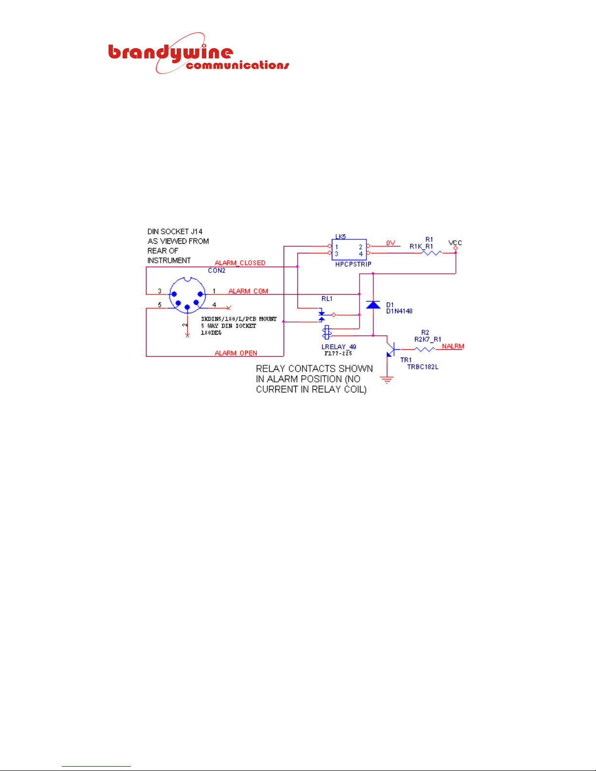
3.12 Alarm Contacts (J14)
The status output is provided by relay RL1, which has a normally open and a
normally closed contact with changeover to a common terminal. LK5 inside of
the unit allows jumpers to be placed which provides optional connection to 0 V
and 5 V for Alarm_Open and Alarm_Closed respectively as shown below. Signal
NALRM turns on TR1 to hold the relay in a non-alarm state. If signal NALRM
goes ‘low’, the relay contact changes to the alarmed condition. If power is
available, the red STATUS indicator will be illuminated on the front panel of the
unit.
55
MANUAL P/N 900000007 REV 2.0
Page 56
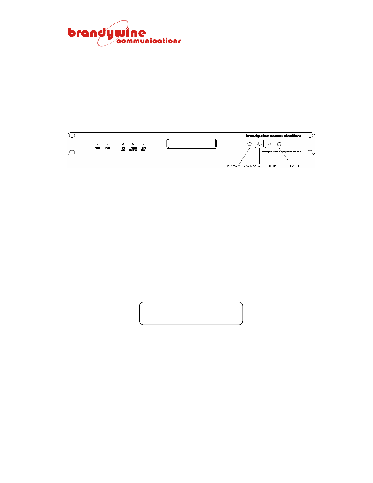
4 GPS8 Plus Keypad and Display Operation
4.1 Scope of Section
Section 4 provides a description of the GPS8 PLUS keypad and display
operation.
4.2 General Principles of Operation of Keypad and Display
The display has two lines of 24 characters and its function is organized as a
series of two line screens displaying information to the user. The screens are
easily selected after initialization by use of the arrow keys, pressing the Up Arrow
key for the next screen or the Down Arrow key for the previous screen.
The keypad offers simple yet rapid operation through 4 keys, the ‘Up Arrow’,
‘Down Arrow’, ‘ENTER’, and ‘ESCAPE’.
Some screens allow the user to enter data for GPS8 Plus configuration.
Pressing ENTER will allow the user to enter data, which will freeze the current
screen and turn on a cursor next to the item to be modified. After modification,
the user may exit the display without saving the entry by pressing ESCAPE or
confirm the entry by pressing ENTER. If a screen does not allow data entry and
ENTER is pressed in an attempt to enter data, the brief message seen below is
displayed.
*NO DATA ENTRY POSSIBLE*
56
MANUAL P/N 900000007 REV 2.0
Page 57
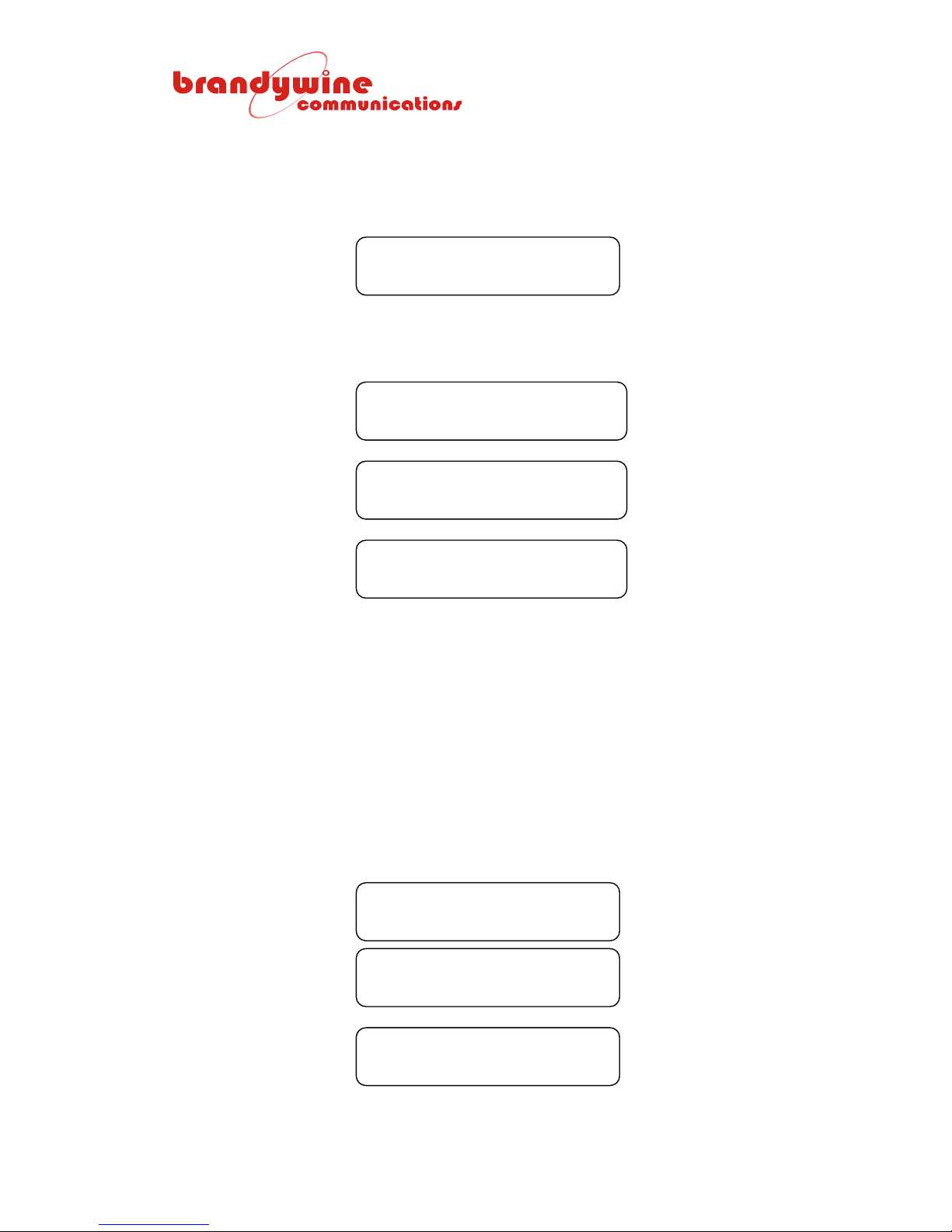
4.3 Messages after Power On
At power on an update of the screen will begin. A blank screen such as the one
seen below is displayed. During this time the user can initiate the download of
new firmware to the flash memory of the GPS8 Plus.
▒▒▒▒▒▒▒▒▒▒▒▒▒▒▒▒▒▒▒▒▒▒▒▒
The series of messages below are displayed during the initialization process
while the initialization and test are carried out. Afterwards, the main default
screen with the time of day and status is finally reached.
RAM...PASS NV_RAM...PASS
ROM...PASS
RAM...PASS NV_RAM...PASS
Test Alarm & LEDs....
POWERUP 00:00:07 001 UTC
THU JAN1 2004
At power down the GPS8 Plus does not retain the time and date. At power up it
increments the time from switch on. The screen with the time indicates the
status of the time as seen in the POWERUP screen above. Other screens are
selected by pressing the Up Arrow and Down Arrow keys, which are described
below. When a different screen is selected from the main default screen and
data entry is not in progress, pressing ESCAPE will return the user to the main
default screen.
At the main default screen when data entry is not in progress, pressing ESCAPE
will select and display the internal sounder state. The three possible internal
sounder states are shown below. The message describing the sounder state is
displayed briefly on the top line of the screen.
SOUND IS GPS ENGINE 1PPS
WED MAR 24 2004
SOUND IS INT OSC 1PPS
WED MAR 24 2004
SOUND IS OFF
WED MAR 24 2004
57
MANUAL P/N 900000007 REV 2.0
Page 58

4.3.1 Op eratin g M od e Sele ction
GPSLOCK 21:30:25 084 UTC
WED MAR 24 2004
The main default screen normally looks like the screen seen above after a few
minutes of operation. The first field in the top line allows the user to select one of
three operating modes. The mode is selected by pressing ENTER, which
displays an arrow with a blinking cursor. Pressing the Up Arrow and Down Arrow
keys allow the user to review the three modes of operation listed in the table
below. A mode is selected by pressing ENTER. This mode is remembered after
power down therefore this mode continues at the next power up.
MODE DESCRIPTION
GPSLOCK Normal operation of the GPS8 Plus as a disciplined GPS time and frequency
standard.
FREERUN Operation of the GPS8 Plus as a free running time and frequency source. In this
mode the user can enter the time and date and press ENTER to run from that time.
No corrections are applied from the GPS. If the selection of FREERUN is confirmed
by pressing ENTER followed by ESCAPE to quit the time and date entry, the GPS8
Plus will continue to run from the current time with the frequency control frozen at
the last setting. The subsequent time difference over 1 second against the GPS
can be seen on the Instantaneous Phase report. Mean Phase and Frequency
Difference are estimated until the phase error exceeds 15 microseconds.
PPSLOCK Operation of the GPS8 Plus as a disciplined time and frequency standard using only
the 1 PPS derived from the GPS receiver. In this mode the user can enter the time
and date and press ENTER to run from that time. The entered time is corrected to
run in synchronism with the real time 1 PPS from the GPS receiver with no use of
the time or date information from the GPS.
4.3.2 GP S Lo cked Mode
This is the default mode during normal operation as a disciplined time and
frequency standard. The normal status of GPSLOCK may be replaced by one of
the statuses described in the table below.
STATUS DESCRIPTION
POWERUP GPSLOCK is selected, but the GPS8 Plus has not yet acquired time and is running
from the initialized time and date at switch on with frequency outputs set using
corrections remembered from the previous operation.
HLDOVER GPSLOCK is selected, but data from the GPS receiver cannot be used or is not
available. The time and date continue to count from the last time locked to the
GPS. (The last frequency controller update time, day number, and elapsed
holdover time are available on other displays.)
SLEWING GPSLOCK is selected, the time and date have been acquired, and the
synchronization process is slewing the GPS8 Plus time and date into synchronism
with the GPS.
LOCKING GPSLOCK is selected, the time and date have been acquired, but the continuous
locking process has not been completed and the time and date are not confirmed
as valid.
GPSLOCK Normal presentation when the time displayed from the GPS8 Plus clock/calendar
was updated from the GPS data in the previous second and the frequency of the
time-base is being corrected by the 1 PPS from the GPS.
58
MANUAL P/N 900000007 REV 2.0
Page 59
4.3.3 Free Run Mode
Only the description FREERUN is displayed in the status field for this mode. The
status is described below.
STATUS DESCRIPTION
FREERUN The time clock is running from the GPS8 Plus internal TCXO, OCXO, or Rubidium
frequency standard and is never updated by data from the GPS. Likewise, the
frequency of the time-base is fixed at the last correction value applied by the
controller. If this mode was selected after GPSLOCK and the user pressed
ESCAPE to quit the time and date entry, then the time is continuing to count from
the last GPS time received. Otherwise it counts from a keypad entered time (see
section 4.3.5) or from the initialized time at switch-on.
4.3.4 1 PPS Lock Mode
When PPSLOCK mode has been selected the three possible status indications
shown in the table below replace PPSLOCK until the locking process is complete
or during moments when the locking process is interrupted. The statuses are
described below.
STATUS DESCRIPTION
PPSLOCK The GPS8 Plus is running as a disciplined time and frequency standard using only
the 1 PPS derived from the GPS receiver as a reference. If this mode was selected
after GPSLOCK and the user pressed ESCAPE to quit the time and date entry, then
the time is continuing to count from the last GPS time received. Otherwise it counts
from a keypad entered time (see section 4.3.5) or from the initialized time at switchon.
PPSLKNG The locking process has not been completed. The time displayed is the time
continuing from the moment the PPSLOCK mode was selected or from manual
keypad entry, which is being synchronized by the GPS8 Plus to the reference 1
PPS update.
NO 1PPS The GPS8 Plus is in PPSLOCK mode, but no 1 PPS is being detected. Time and
date continue to be maintained from the free-running GPS8 Plus internal frequency
standard.
4.3.5 Manual Time and Date Entry
The time and date can only be entered in FREERUN or PPSLOCK mode and
only UTC may be entered. Pressing ENTER will freeze the displayed time and
date (while all outputs continue with the current advancing time and date). When
ENTER is pressed again this confirms the mode. The displayed up arrow with
the blinking cursor moves to the colon position allowing the user to enter the
hours. At any point prior to the last date entry the user may quit the time entry
process by pressing ESCAPE and the GPS8 Plus time and date will be restored.
The Up Arrow and Down Arrow keys are used to adjust each field and the
selected value is confirmed by pressing ENTER. After the selected value is
confirmed the blinking cursor moves to the next field. This way the user
proceeds in the order of hours, minutes, seconds, year, month, and day of month
number. The year number is selected or confirmed prior to the day of month
entry to allow the correct number of days to be displayed for February.
59
MANUAL P/N 900000007 REV 2.0
Page 60
For FREERUN mode, pressing ENTER after the day of month number updates
the time-base values with the entered values and the count will continue from this
moment. The Time Valid indicator is illuminated and the outputs that use the
status show time as being valid to permit the testing of systems that require it.
The day of week is calculated by the GPS8 Plus and does not require data entry.
For PPSLOCK mode, pressing ENTER starts a synchronization process that
synchronizes the entered time to the 1 PPS reference. Synchronization is a
combination of jam-sync, time-slewing, and fine frequency adjustments
depending on the magnitude of the time interval between the user’s final press of
the ENTER key and the 1 PPS update. When lock has been acquired,
PPSLOCK is displayed and the Time Valid indicator is illuminated.
4.4 Position Screen
From the time and date screen, pressing the Up Arrow key once selects the
position screen.
N51°47.1378’E000°49.8364
ALT:00006.5m MODE: KNWN
No data entry is possible for this screen. The top line shows the latitude in
degrees, minutes, and decimal fractions of minutes followed by the longitude in
the same units. The second line shows the altitude in meters. The following four
possible modes are described in the table below.
MODE DESCRIPTION
NONE Initialized value of the field while the status is being established from the receiver.
ACQ The receiver is acquiring satellite and almanac data, if required. The GPS8 Plus
requires a recent UTC parameter from the almanac and will not indicate valid time prior
to this acquisition. The position display is not yet valid.
NAV The receiver is navigating – a valid position is displayed.
KNWN The GPS8 Plus has averaged the position data over 24 hours of operation,
downloaded the precise position to the receiver, and commanded it into KNOWN
position mode. The ‘known’ position is the one displayed. This is the standard mode
of operation giving the highest time and frequency accuracy for static users of the
GPS8 Plus. A dynamic position finding mode is available for other applications.
Selection is described in section 4.11.
4.5 Satellites Tracked Screen
From the position screen, pressing the Up Arrow key once selects the satellites
tracked screen.
SATELLITES TRACKED: 8
03 15 16 18 21 22 27 31
No data entry is possible for this screen. The top line shows the number of
satellites tracked and the bottom line shows their PRN numbers.
60
MANUAL P/N 900000007 REV 2.0
Page 61
4.6 1 PPS Status Screen
From the satellites tracked screen, pressing the Up Arrow key once selects the 1
PPS status screen.
1PPS STATUS: SAMPLE USED
INST PHASE:+50ns
No data entry is possible for this screen. The top line gives some information
about the status of the reference 1 PPS and the bottom line indicates the latest
instantaneous time interval from the GPS8 Plus 1 PPS to the reference 1 PPS.
A positive sign indicates that for this sample, the unit 1 PPS was ahead of the
reference 1 PPS from the receiver. The measurement is normally displayed in
nanoseconds, but for large time differences microseconds or milliseconds are
used. For example, a GPS8 Plus fitted with TCXO (the lowest grade of internal
oscillator) that has been allowed to free run for several days may have a screen
similar to the one seen below.
1PPS STATUS: FREE RUN
INST PHASE:+4.03240ms
The status indications that are possible are explained in the table below. The
first message in the list is the one that is displayed if that status is detected, but
other conditions further down the list may also apply. The aim is to give the user
the best possible guide to the 1 PPS measurement and the GPS8 Plus
subsequent action. The magnitude of the instantaneous measurement is always
reported even when it cannot be used.
STATUS DESCRIPTION
FREE RUN 1 PPS samples are not being used because the user has selected the FREE
RUN mode of operation. The 1 PPS instantaneous phase continues to be
reported.
DAC AT LIM The 16 bit DAC controlling the GPS8 Plus reference oscillator frequency has
less than 12% control range remaining. The most probable explanation is that
the user has commanded the DAC to its maximum or minimum setting for test
purposes and the message is a reminder of why 1 PPS samples cannot be
used.
TIMREC NVAL The 1 PPS reference could not be used because the 1 PPS is marked as
invalid by the GPS receiver.
REJECT TIME The time data from the receiver for this second was rejected by the GPS8
Plus because of apparent data errors.
PHASE LIMIT The 1 PPS instantaneous phase measurement is rejected because the value
exceeds the limit accepted for the GPS8 Plus frequency reference.
LOOP FROZEN The user has initiated a GPS8 Plus test (such as centering the DAC) so the
frequency controller is disabled.
SAMPLE USED The instantaneous phase measurement has been used in the phase averager
and for frequency estimation.
61
MANUAL P/N 900000007 REV 2.0
Page 62
4.7 Mean Phase Screen
From the 1 PPS status screen, pressing the Up Arrow key once selects the mean
phase screen.
MEAN PHASE: 29ns
HOLDOVER: 00:00:00
No data entry is possible for this screen. Calculation of the mean phase of the
GPS8 Plus 1 PPS from the received 1 PPS is carried out for the 1 PPS samples
that have been accepted as valid. The samples are placed in a buffer to allow a
moving average calculation of the phase. At each new second, if the sample is
accepted, it is placed in the buffer while the oldest accepted sample is removed
and the mean of the buffer contents is calculated. The first line of the screen
shows the result. The second line of the screen has a count of hours, minutes,
and seconds with a maximum of 99 hours, 59 minutes, and 59 seconds. The
count is incremented during any period in which the GPS8 Plus is unable to
obtain or use correction data for its time and frequency controller and is reset
when the correction data is again available.
The mean phase calculation is carried out even when in FREE RUN mode.
However, the magnitude of the phase measurements accepted depend on the
quality of the oscillator fitted to the GPS8 Plus and when the range is exceeded
the screen will typically show the message seen below.
MEAN PHASE: OUT OF RANGE
HOLDOVER: 84:12:48
In this example the GPS8 Plus has been commanded into the FREE RUN mode
and the phase readings are out of range for the averager. The instantaneous
phase which is always reported over a range of ±0.5 seconds will be available on
the previous screen. The HOLDOVER counter shows that the GPS8 Plus has
run for over 84 hours in this mode.
62
MANUAL P/N 900000007 REV 2.0
Page 63
4.8 Estimated Mean Frequency
From the mean phase screen, pressing the Up Arrow key once selects the
estimated mean frequency screen.
ESTIMATED MEAN FREQUENCY
-2.4E-11 over 1000s
FREQUENCY DESCRIPTION
ESTIMATED
MEAN
FREQUENCY
The frequency calculation from the movement in the MEAN PHASE over the
measurement interval indicated. The mean phase is saved at regular sample
intervals in a 100 sample buffer. The measurement interval is increased from 1
to 10 sample intervals. When 101 samples have been collected, the
calculation is carried out over the full 100 samples on a rolling basis. In this
stage at each sample interval the latest phase sample is entered into the
buffer, the earliest is discarded, and a new frequency result is displayed. The
time between samples is varied according to the oscillator type to increase the
resolution of the measurement. The purpose is to give the user a guide to the
most recent performance of the unit over the previous measurement interval.
4.9 Frequency Control
From the estimated mean frequency screen, pressing the Up Arrow key once
selects the frequency control screen.
FRQ CTRL:-71 AUTO SLO
+0.0E-14 at 012 17:36:00
In this screen the number after FRQ CTRL: is the value of the 16 bit DAC that
controls the GPS8 Plus oscillator frequency. The center frequency of a particular
oscillator is not necessarily at zero and the calculated DAC position includes an
offset for the oscillator calibration, which is updated after the unit has been
switched on and allowed to discipline the oscillator for at least several hours.
The range of control is -32768 to +32767. After the DAC value the status of the
frequency controller is indicated.
STATUS DESCRIPTION
AUTO SLO The status of the controller is indicated as AUTO for normal automatic frequency
control. The word AUTO is followed by FST, MED or SLO. At start-up larger
excursions in frequency are applied to help drive the local clock system quickly
into phase and frequency synchronization with the GPS reference. As soon as
this short term correction history has built an approximate 'integral' value for the
controller (typically less than 15 minutes) the correction rate drops from FAST to
MEDIUM. Control continues in MEDIUM for at least 36 hours refining the ‘integral’
before switching automatically to SLOW.
FREERUN The screen is not being updated because the FREE RUN mode has been
selected (see 4.3.1)
63
MANUAL P/N 900000007 REV 2.0
Page 64
4.9.1 Test Configuration of Frequency Controller
User configuration for test purposes is possible for this screen. Pressing ENTER
displays the blinking cursor next to the word AUTO. Use the Up Arrow key to
select one of the following modes for test purposes. Pressing ENTER confirms
the selection, whereas pressing ESCAPE quits the selection and makes no
changes. When the testing has been compl e ted, make sure t hat AU TO is
reselected, otherwise the GPS8 Plus will not reacquire GPS LOCK.
MODE DESCRIPTION
FST ONLY Lock the frequency controller in the FAST update mode.
CENTER Set the electronic frequency control to its center value for oscillator testing or
adjustment.
FREEZE Lock the frequency controller DAC at its current setting.
SET MIN Set the frequency to maximum.
SET MAX Set the frequency to minimum.
Setting the frequency to maximum or minimum will cause an alarm because the
DAC value exceeds the alarm threshold. The lower line of this screen shows the
magnitude of the latest correction in frequency of the GPS8 Plus’ frequency
standard and the time at which it was applied. In the FAST controller setting the
oscillator is adjusted at every second if a valid phase comparison with the
reference 1 PPS is obtained. In MEDIUM and SLOW controller setting the time
between corrections depend on the quality of the installed oscillator.
4.10 Position Mode Configuration
From the frequency control screen, pressing the Up Arrow key once selects the
position mode configuration screen.
POSN. MODE CONFIGURATION
MODE: AVERAGE SAMPLE:100
The screen shows the current positioning mode and in the case of the position
average mode the number of current position samples. The position averaging is
the default mode of operation for the GPS8 Plus. The mode can be changed to
suit dynamic applications in which averaging cannot be used.
When averaging is used the target number of samples is 100. The position
samples are values of latitude, longitude, and altitude obtained when the GPS8
Plus receiver is navigating with reasonable dilution of precision (DOP). The
collection of 100 samples require about 24 hours during which the sample
counter on this screen indicates its progress. After sample 100 has been
obtained the GPS8 Plus calculates the average position, transmits it to the GPS
receiver, and commands the receiver to operate in this KNOWN position. After
receipt of the command the position finding mode KNWN is shown on the
position screen described in section 4.4 and the position shown is the averaged
position.
64
MANUAL P/N 900000007 REV 2.0
Page 65

4.10.1 Position Mode Selection
To select an alternative mode of operation, the user must press ENTER in this
screen which will then display an up arrow with the blinking cursor positioned in
front of AVERAGE as seen in the screen above. Pressing the Up Arrow or Down
Arrow key allows STATIC or DYNAMIC positioning mode to be selected. The
desired mode is confirmed by pressing ENTER, whereas pressing ESCAPE will
quit the selection without making any changes. For the current receiver, STATIC
or DYNAMIC mode offers the same type of operation. The receiver carries out
position estimation continuously on a second by second basis.
4.11 Local Time Configuration
From the position mode configuration screen, pressing the Up Arrow key once
selects the local time configuration screen. At this screen the user can select
whether the GPS8 Plus outputs are in UTC or local time and the magnitude of
the offset of the local time from the UTC.
LOCAL TIME CONFIGURATION
OUTPUT:UTC OFFSET:+01:00
The screen shows the currently selected output mode (UTC or LOC) and the
hours and minutes offset that would be applied if local time outputs were
selected. A positive sign indicates that the outputs will be advanced in time when
the local time is selected.
4.11.1 Local Time Offset Adjustment
Pressing ENTER will position an up arrow with the blinking cursor in front of the
UTC. The user can toggle from UTC to LOC by pressing an arrow key. At the
desired selection ENTER is pressed, which moves the up arrow to the colon
position before the sign, allowing the user to select the sign. Pressing an arrow
key will toggle the sign and pressing ENTER moves the cursor to the colon
position after the hour offset. The Up Arrow and Down Arrow keys are used to
select the hour offset required. At this point pressing ESCAPE restores the
original settings with no changes. Alternatively, pressing ENTER confirms all
selections and completes the edit process for this screen.
65
MANUAL P/N 900000007 REV 2.0
Page 66
4.12 Time Code Configuration
From the local time configuration screen, pressing the Up Arrow key once selects
the time code configuration screen. On selection its function is displayed in the
top line for 2½ seconds.
TIMECODE CONFIGURATION
IRIG B TIMED TYP2 TYP3
The description TIMECODE CONFIGURATION in the top line is then replaced by
the names of the output ports as headers to their current settings in line 2 of the
screen.
J8 J10(DC) J13 J12
IRIG B TIMED TYP2 TYP3
4.12.1 Time Code Selection
Pressing ENTER will cause an up arrow with the blinking cursor to be displayed
in front of the time code name under J8. The Up Arrow and Down Arrow keys
are used to scroll through the list of IRIG B, 2137, VELA, NASA36, AFNOR, or
NONE. These time codes are amplitude modulated onto a 1 KHz carrier that has
positive going zero-crossings ‘on time’. The selection NONE results in an unmodulated 1 KHz sine wave output. Press ENTER to confirm the selection.
The arrow moves the description of the output to J10. J10 is a logic level output
at 0 to 5 V from 50R. It can output timed pulses (at times and durations which
can be selected at the next screen). Pulses at defined periods (selectable at the
next screen) or un-modulated time code that is exactly the same as the time
code for J8.
J10 MODE DESCRIPTION
IRIG B The port outputs the same time code as J8 as a DC level, 0 to 5 V from 50R.
IRIG B has been selected as the time code for J8.
TIMED One pulse per day to one pulse per second with 1 ms to 9999 ms duration. The
normal level can be 0 V with pulse level 5 V or the normal level can be 5 V with 0
V for the duration of the pulse. ‘Don’t care’ selections at the entry of hours,
minutes, or seconds allow pulses to be outputted more frequently than once per
day.
PERIOD In this mode the user defines period of pulses and pulse length. The period range
is 2 ms to 9999 ms and the pulse length is 1 ms to 9998 ms (always less than the
period).
NONE No output from J10.
Section 4.14 describes how to set up the TIMED or PERIOD parameters for the
pulse output from J10.
66
MANUAL P/N 900000007 REV 2.0
Page 67
4.12.2 J13 TXD1 Configuration
After confirmation of the J10 mode, pressing ENTER places the cursor next to
J13. The description ‘TYP2’ is fixed for this port and cannot be changed by the
arrow keys. J13 is the GPS8 Plus asynchronous serial interface RxD1/TxD1
which provides time, position, and status data on request from the user (see
section 3.5). As regards to the time code, it has a fixed Type 2 serial data
message, which is requested by the user by sending the ‘t’ request to J13 RxD.
4.12.3 J12 TXD2 Configuration
Pressing ENTER again places the cursor next to the output from J12. J12
carries the TxD2/RxD2 asynchronous serial interface and the outputs are in one
of three message formats described in section 3.7. The arrow keys make the
format selection. Pressing ENTER confirms all selections in this screen. The
data is automatically outputted once per second in the selected format unless it is
requested by transmission of the ‘t’ request to RxD2 at J12. After the ‘t’ request
the unit responds with a single message to each ‘t’ received. The automatic
mode is resumed by sending ‘r’ to the port.
TYPE EXAMPLE OF OUTPUT FROM J12
TYP1 00:00:00 00/00/00 000 0<CR><LF> until time is valid
20:34:03 08/11/91 312 5<CR><LF>
TYP2 20:34:03.123 17/03/88 077 2 9<CR><LF>
TYP3 2001, 156:15:17:43, 3, 1<CR><LF>
67
MANUAL P/N 900000007 REV 2.0
Page 68
4.13 J10 Pulse Output Configuration
From the time code configuration screen, pressing the Up Arrow key once
selects the J10 pulse output configuration screen. On selection the function of
the screen is shown in the top line for 2½ seconds.
J10 PULSE CONFIGURATION
CODE: IRIG B (TC1 AS DC)
The function message is replaced by a line describing the output from J10.
Pressing ENTER positions the cursor on the up arrow before TIMECODE.
Pressing the Up Arrow or Down Arrow key selects other possible modes for the
J10 output.
J10 :↑TIMECODE (DC)
CODE: IRIG B (TC1 AS DC)
J10 :↑TIME LENGTH POL
UTC 00:00:00 100ms +
J10 :↑PERIOD LENGTH POL
1000ms 100ms +
J10 :↑ NO OUTPUT
4.13.1 J10 Timed Pulse Configuration
J10 : TIME LENGTH POL
UTC↑00:00:00 100ms +
Select TIME as the mode for the pulse and press ENTER. The up arrow moves
to the position after UTC allowing the user to press the Up Arrow or Down Arrow
key to toggle UTC to LOC for selection of the pulse time. UTC chooses UTC for
the following time of pulse output. LOC chooses local time for the field that
follows.
Press ENTER to move to editing the hour field, which can be incremented or
decremented from 00 through 23 using the Up Arrow or Down Arrow key. Above
23 or below 00 the “don’t care” selection XX is shown on the screen. For this
selection, hours are not used in the time of day comparison. The user can
subsequently define minutes and seconds so a pulse will be outputted every
hour.
68
MANUAL P/N 900000007 REV 2.0
Page 69
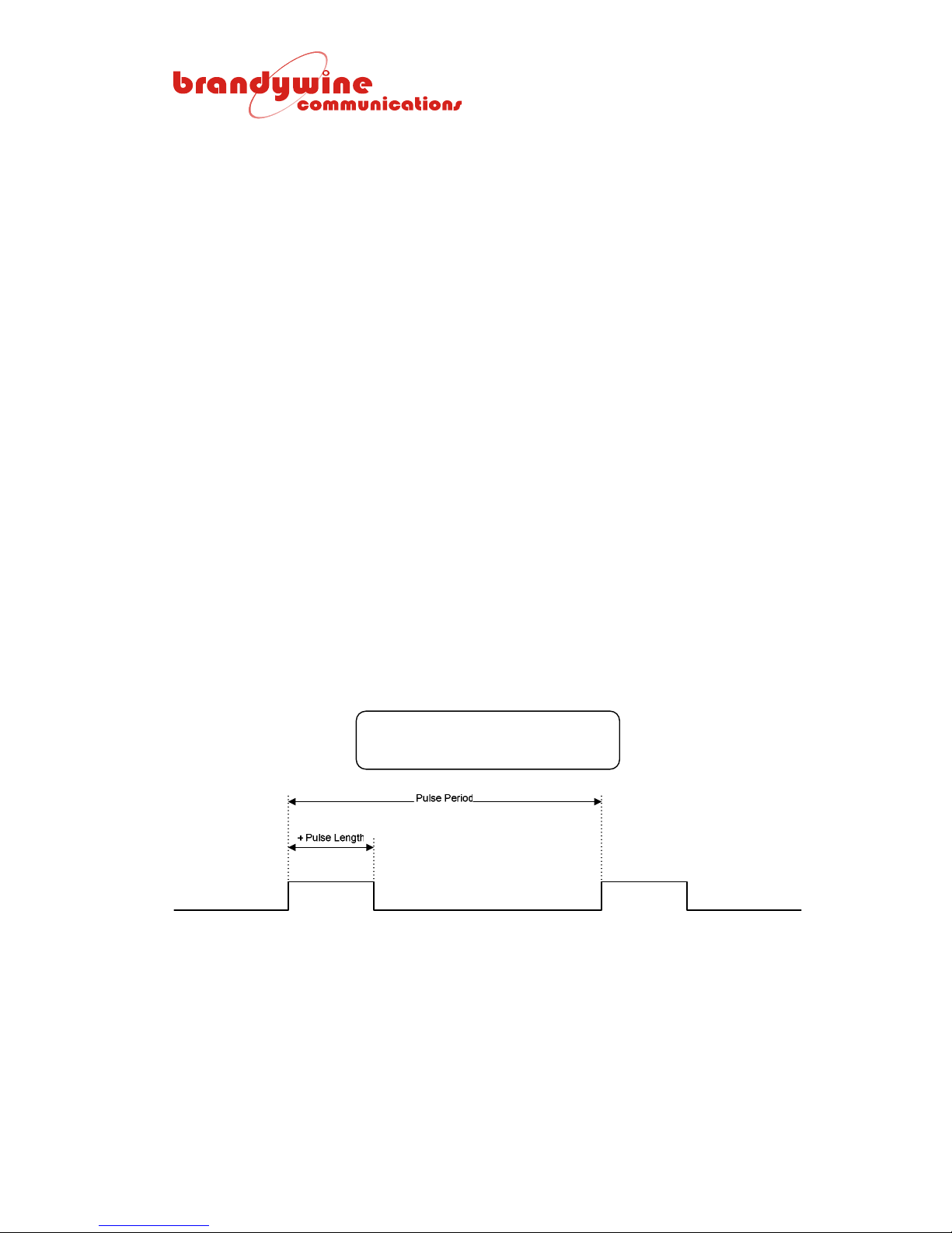
Press ENTER to edit the minute field and choose the minute count at which the
pulse is outputted from 00 to 59. Again an extra count XX is included for
selection when the minutes are not used in the time of day comparison. With
hours similarly selected the pulse will be outputted once per minute. Press
ENTER to accept the minute entry and choose the seconds count for the pulse.
Once again 00 to 59 or XX can be selected. For XX:XX:XX seconds are
excluded from the comparison so the pulse is outputted every second.
When the time of day for the J10 pulsed output has been entered the cursor
moves to the LENGTH field and the screen shows leading zeros to allow the user
to edit the 1000 s, 100 s, and 10 s. The cursor blinks on the 1000 ms digit and a
value 0 to 9 can be selected using the Up Arrow and Down Arrow keys. Press
ENTER at the desired value and the cursor moves to the 100 ms digit. In this
way the user enters or confirms existing digit values through to 1 ms for the pulse
length definition as a value of 1 ms to 9999 ms.
After the pulse length entry or confirmation the cursor moves to the sign field,
allowing a normal positive going pulse to be specified by selecting or confirming
the ‘+’, or if desired the ‘-‘ can be selected with the arrow key. For a positive
pulse the output of J10 is at 0 V and jumps to 5 V for the output duration of the
pulse. For a negative pulse, the reverse is true. The output of J10 is at 5 V and
jumps to 0 V for the output duration of the pulse.
Pressing ESCAPE allows the user to return to the previously defined values for
the pulse with no change in operation. Only when pressing ENTER for the final
time are the values applied.
4.13.2 J10 Pulse Period Configuration
J10 : PERIOD LENGTH POL
1000ms 200ms +
The pulse period may be 2 ms minimum to 9999 ms maximum and the pulse
width is 1 ms minimum to 9998 ms maximum, but always less than the period.
69
MANUAL P/N 900000007 REV 2.0
Page 70

Select PERIOD as the mode for the pulse and press ENTER. The cursor moves
to the 1000 ms digit displayed as 0 if it is not used in the current definition.
Select the required value using the arrow key and confirm it by pressing ENTER
which moves the cursor to the hundredth digit. When each digit has a value
press ENTER until all four digits are set. Do not enter a period less than the
minimum value of 2 ms. The final ENTER moves the cursor to the pulse length
entry. The cursor blinks on the 1000 ms digit of the pulse length and a value 0 to
9 can be selected using the arrow keys. Press ENTER at the desired value and
the cursor moves to the 100 ms digit. In this way the user enters or confirms
existing digit values through to 1 ms for the pulse length definition as a value of 1
ms to 9998 ms. The pulse length minimum is 1 ms and the pulse length must be
less than the period.
After the pulse length entry or confirmation the cursor moves to the sign field,
allowing a normal positive going pulse to be specified by selecting or confirming
the ‘+’, or if desired the ‘-‘ can be selected with the arrow keys. For a positive
pulse the output of J10 is at 0 V and jumps to 5 V for the output duration of the
pulse. For a negative pulse, the reverse is true. The output of J10 is at 5 V and
it jumps to 0 V for the output duration of the pulse.
Pressing ESCAPE allows the user to return to the previously defined values for
the pulse with no change in operation. Only when pressing ENTER for the final
time are the values applied. The first pulse to be outputted is synchronized with
the GPS8 Plus time.
4.13.3 J10 Pulse Time Code Configuration
J10 : TIMECODE (DC)
CODE: IRIG B (TC1 AS DC)
J10 time code output is a logic level version of the modulated carrier time code
that is outputted on J8. Refer to section 4.13 for information on how to select the
time code.
70
MANUAL P/N 900000007 REV 2.0
Page 71
4.14 Status Screen and Alarm Configuration 1
From the J10 pulse output configuration screen, pressing the Up Arrow key once
selects the alarm configuration 1 screen. The function of this screen is displayed
in the top line of the screen for 2½ seconds followed by a list of output sockets
and their status.
ALARM CONFIGURATION 1
J6 J5 J4 J3 J2 J1
NRM NRM NRM NRM NRM NRM
The primary purpose of the screen is to list the status of the monitoring circuits
for the signals out of J1 through J6. For outputs which are normal, NRM is
displayed underneath the connector number. For outputs which are judged
faulty, FLT is displayed. Any output that is FLT will cause the GPS8 Plus status
relay to be deactivated signaling an alarm that turns on the red Fault LED on the
GPS8 Plus front panel. The fault monitors are not latched and clear
automatically when the output signals return to normal levels. There are
occasions when the user may not want a particular output to contribute to the
overall GPS8 Plus status report by deactivating the status alarm status relay.
The alarm configuration screen allows any of the output status reports to be
removed from the OR function that signal the unit alarm. This function is useful
for outputs which are not used in a particular configuration.
4.14.1 Selection of Alarm Masks 1
Selecting the outputs to be removed from the alarm function is accomplished by
pressing ENTER. An up arrow with a blinking cursor is shown on the screen
after J6. Continue to press ENTER until the cursor is adjacent to the output that
is to be removed from the alarm function. Use the arrow key to toggle the alarm
mask ON or OFF. When the mask is applied the status NRM or FLT is displayed
as ---. In the example below the output from J5 is not required and any possible
alarm state has been masked by the user’s selection.
J6 J5 J4 J3 J2 J1
NRM --- NRM NRM NRM NRM
User mask settings are saved in EEPROM with a check byte. The settings are
initialized to the same state at the next power up.
71
MANUAL P/N 900000007 REV 2.0
Page 72
4.15 Status Screen and Alarm Configuration 2
From the J10 pulse output configuration screen, pressing the Up Arrow key once
selects the alarm configuration 2 screen. The function of the screen is displayed
in the top line of the screen for 2½ seconds followed by a list of the alarm
sources and their statuses.
ALARM CONFIGURATION 2
SYN Rb J10 J9 J8 J7
NRM --- NRM NRM NRM NRM
The first alarm source listed on this screen is SYN, the PLL synthesizer for
telecom or other special frequency generation. SYN indicates NRM for a
correctly locked synthesizer or FLT is shown for an out-of-lock condition.
The second source listed is Rb under which is indicated the status of an optional
Rubidium frequency standard in the unit. As a default this source is already
masked. When a Rubidium is fitted, the status condition may be CLD, NRM, or
FLT. CLD indicates that the Rubidium has not yet warmed up and its status is
likely to indicate that it is not resonance locked. If it remains unlocked when it
has warmed up, then FLT is indicated for the Rubidium status.
The remaining alarms are for the signals on the output sockets J10 through J7.
They operate in the same way as the alarms on J6 to J1 described in section
4.14. None of the alarm sources on the Alarm Configuration 2 screen is latched
and the alarm is cleared when the fault clears.
4.15.1 Selection of Alarm Masks 2
In each case the associated alarm signal can be masked as described in
paragraph 4.14.1. User mask settings are saved in EEPROM with a check byte.
The settings are initialized to the same state at the next power up.
72
MANUAL P/N 900000007 REV 2.0
Page 73
4.16 Status Screen 3
From the alarm configuration 2 screen, pressing the Up Arrow key once selects
the third status screen. Alternatively, from the main default screen of the time
and date, pressing the Down Arrow key twice accesses it.
SYNC FRQ DAC SATS
NRM NRM NRM NRM
The status conditions listed contribute to the overall alarm on the GPS8 Plus and
will result in the alarm status being asserted by the alarm relay and the front
panel red Fault LED will be turned on.
NAME DESCRIPTION
SYNC Set to FLT shows that the synchronization process has been interrupted. During start
up or if a re-synchronization becomes necessary after a very long holdover period, the
synchronization process is launched automatically by the GPS8 Plus when error-free 1
PPS signals are available from the receiver. A further 1 PPS is required to complete the
synchronization and might have been disabled at that instant. It will automatically be
cleared to NRM when the procedure has been successfully completed.
FRQ Set to FLT if the GPS8 Plus is unable to discipline its oscillator to follow the GPS. It will
automatically be cleared to NRM when the GPS8 Plus succeeds in controlling the
oscillator.
DAC Set to LIM when the DAC that controls the frequency of the GPS8 Plus TCXO, OCXO,
or Rubidium is within ±12% of its maximum or minimum setting. It will automatically be
cleared to NRM when the DAC is inside the 12% limit of remaining control.
SATS No satellites have been tracked for more than 8 hours.
4.17 Status Screen 4
From the third status screen, pressing the Up Arrow key once selects status
screen 4. Alternatively, from the main default screen of the time and date,
pressing the Down Arrow key once accesses it.
ISSUE ROM RAM NV_RAM
23P NRM NRM NRM
NAME DESCRIPTION
ISSUE Heading to the firmware issue number.
ROM Set to FLT if the flash memory or EPROM contents give rise to a checksum error
during initialization.
RAM Set to FLT if the RAM fails a comprehensive check during initialization.
NV_RAM Set to FLT if the battery-backed RAM contents fail a checksum test during
initialization. If NV_RAM shows FLT, then the stored parameters are updated by the
default values until new values are entered or acquired. After a firmware upgrade,
NV_RAM status may be deliberately set to FLT to force its initialization at the first
power on of the new firmware.
If the name is set to FLT after power on, then the items do not contribute to the
alarm relay or Fault LED activation. If the ROM, RAM, or NV_RAM persistently
show status errors consult the manufacturers.
73
MANUAL P/N 900000007 REV 2.0
Page 74

5 Principles of Operation
5.1 Scope of Section
Section 5 provides a functional description of the GPS8 Plus and a general
description of the Global Positioning System.
5.2 Theory of Operation
Operation of the Global Positioning System is based on the principle that the
position of an object can be determined by measuring the distance to three or
more satellites of known positions. The GPS8 Plus receiver system determines
the distance to each satellite by measuring the time taken for the signal to arrive
at the antenna (a procedure known as one-way ranging). The signal provides
satellite position and time information, which is used by the receiver to calculate
the antenna position. Satellite position information must be exact with respect to
the earth at the time the signal is transmitted to enable the receiver to
compensate for the constant movement and correctly synchronize with the
satellite data.
Time information derived from a satellite atomic clock provides the receiver with
the exact time of the data transmission. This time is compared with the receiver
clock to calculate transmission time. As the speed of electromagnetic radiation is
constant (2.998 x 10
gives the satellite distance. The receiver automatically solves simultaneous
equations for position and time using the optimum constellation of satellites.
Each satellite also transmits almanac data and status information, which is used
by the receiver to determine which satellites are visible and which four will
provide the most accurate position and hence time and frequency calculations.
Satellite almanac data is particularly important because the coding technique and
satellite motion make a random search for a satellite time consuming. For this
reason almanac data is stored in non-volatile memory and is retained whenever
the receiver is switched off.
The basic GPS8 Plus is comprised of eight main sections as listed below.
1. Receiver/antenna
2. Microcomputer control system
3. Display/keypad
4. Internal oscillator
5. I/O system
6. Power supply
8
meters/sec), multiplying this figure by the transmission time
74
MANUAL P/N 900000007 REV 2.0
Page 75

The satellite transmissions are first received by a remote sealed omni-directional
antenna assembly, which includes a low noise pre-amplifier and coaxial cable for
connection to the main unit. Up to 100 feet of standard RG-58 cable can be used
or 300 feet of RG-8.
The GPS receiver inside the unit is a parallel eight channel unit, which
simultaneously and continuously tracks up to eight satellites. The received time,
position, status, and DOP data is processed and transmitted to the main control
board via a bi-directional RS232 port together with a 1 PPS signal recovered
from the data while tracking at least one satellite. The 1 PPS signal transmitted
by the satellite is aligned to "GPS time", which is offset from UTC by a whole
number of seconds. This offset is automatically removed by the receiver.
All functions associated with input and output control are performed by a
microcomputer system, which also accepts keypad data and provides screen
information for the liquid crystal display if used.
The microcomputer control system has 8 main functions as listed below.
1. Display/keypad control
2. Receiver control
3. Phase control of timing outputs
4. Frequency control of reference oscillator
5. Time code/pulse rate generation
6. Serial/parallel I/O control
7. Built in test/monitoring
8. Expansion selection/control
All control software for the microcomputer system resides in a single 1024 K
flash memory supported by a 512 K ‘boot’ ROM, which permits firmware upgrade
via the unit serial port. Battery backed RAM and EEPROM store various system
parameters during a power down so that constant reprogramming of the unit is
avoided. The sine wave frequency (and as an option IRIG B time code) outputs
are available via isolating transformers.
The unit can be fitted with a number of different types of oscillator, which
provides time and frequency back-up in the event of the loss of satellite
reception, as well as filtering to remove short term variations due to the variability
of the GPS as a timing reference caused by the possibility of selective
availability, which may be introduced to deny the highest positioning accuracy to
non-military users. The drift while the GPS8 Plus is operating without satellite
synchronization (a period known as “holdover”) will depend on the quality of the
oscillator, ambient temperature changes, and the period with no satellite visibility.
However, the high stability grade of the oscillator can achieve better than 10 µs
per day drift in benign environmental conditions.
75
MANUAL P/N 900000007 REV 2.0
Page 76

The complete unit is normally powered by an AC supply, which uses a high
efficiency toroidal transformer to provide two independent low noise supplies
regulated to +5 V for the processor and digital support circuitry and +15 V for the
analog circuits and output distribution circuits. The +15 V is further regulated to
+12 V to maintain low noise and increase isolation.
The analog section of the unit is totally galvanically isolated from the digital
section up to eventual common grounding at the output connectors. The signal
connections between analog and digital sections are made via opto-isolators and
a transformer.
76
MANUAL P/N 900000007 REV 2.0
Page 77
6 Maintenance and Calibration
6.1 Scope of Section
Section 6 describes the recommended maintenance checks for the GPS8 Plus
and outlines a general approach to fault finding and repair.
6.2 Routine Maintenance
During normal operation the GPS8 Plus functions automatically and does not
require continuous manual intervention. Preventative maintenance can therefore
be restricted to a regular inspection of status indicators and displays. The only
component which will degrade with time and may need replacement during the
life of the unit is the battery, which powers the GPS receiver and GPS8 Plus'
RAM when the main power supply is switched off or disconnected.
INSTRUMENT ON TIME APPROXIM ATE BATTERY LIFE
100% 25 years
66% 10 years
0% 3 years
BT1 is mounted in a socket and can be replaced. Before removing the unit’s
cover ensure that the power cord has been detached from the rear of the unit.
Other components which will age and may require adjustment are as follows:
• Liquid crystal display (OPTION ONLY)
• Liquid crystal display
The GPS8 Plus incorporates a variable control RV3, accessible through a hole in
the right-hand side of the case viewed from the front. RV3 is factory set to give
the optimum contrast ratio on the display. During the life of the unit the contrast
ratio may change due to ambient temperature and lighting variations, shock,
vibration, and etcetera. RV3 can be re-adjusted as often as required to optimize
contrast ratio. This adjustment can be made through an access hole in the side
of the unit’s case (the right-hand side of the case viewed from the unit’s front).
77
MANUAL P/N 900000007 REV 2.0
Page 78
6.3 Fault Finding
CAUTION:
In the case of equipment malfunction or failure, it is recommended that
the GPS8 Plus is returned to the factory for repair. If this is not
practical, fault finding and repair must only be undertaken by a qualified
test engineer.
Internal fault finding and repair of the GPS8 Plus requires specialized knowledge.
Identification of a malfunction to a module level is straightforward using the self
test routines and status indicators described on pages 6, 14, and 15. The
following table identifies the most likely module responsible for a fault condition.
BUILT IN TEST SUSPECT MODULE
ANT FLT ANTENNA/RECEIVER
INIT FAIL MICROCOMPUTER
RCVR FLT RECEIVER
OSC I/P FLT INTERNAL OSCILLATOR
FRQ ERR FLT INTERNAL OSCILLATOR
RAM FAIL MICROCOMPUTER
EFC LIM FLT INTERNAL OSCILLATOR
ROM FAIL MICROCOMPUTER
A malfunction of the display module, keypad system, or output interfaces will be
immediately apparent to the user. A major failure of the power supply will cause
a complete loss of functionality. A partial failure can be verified by checking the
DC voltages.
It should be noted that the unit contains static sensitive devices and hazardous
voltages (115 VAC). If measurements and/or adjust ments m ust be made with
the unit switched on it should be powered via an isolation transformer.
6.4 Oscillator Module
The precision oscillator installed in the GPS8 Plus may be one of several
different types. The oscillator is factory installed and does not require further
adjustment. The type of oscillator fitted is detected automatically and is
described in the power on message. The type is specified by 3 jumpers on the
oscillator module and for certain types or optionally an entry in EEPROM
memory.
78
MANUAL P/N 900000007 REV 2.0
Page 79
7 Diagrams
FIGURE DESCRIPTION
1 GPS8 Plus Front Panel
2 GPS8 Plus Rear Panel
3 GPS8 Plus Mechanical Outline
4 GPS8 Plus Link Locations
5 Table of Link Settings 0180BN
6 GPS8 Plus Block Diagram
79
MANUAL P/N 900000007 REV 2.0
Page 80
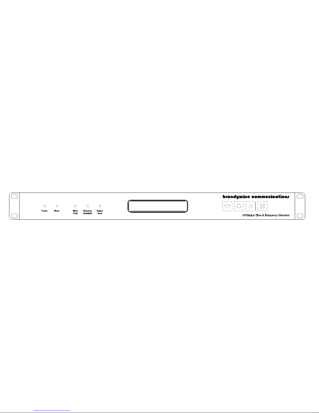
Page 81
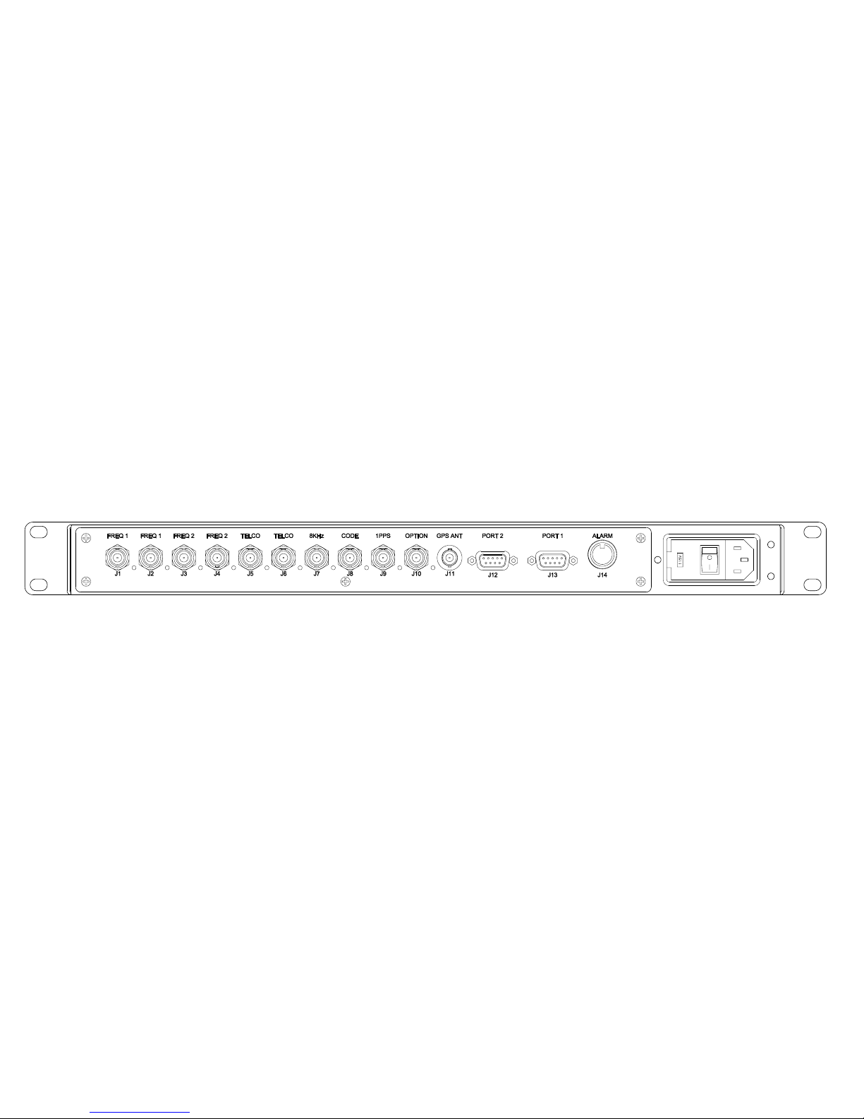
Page 82
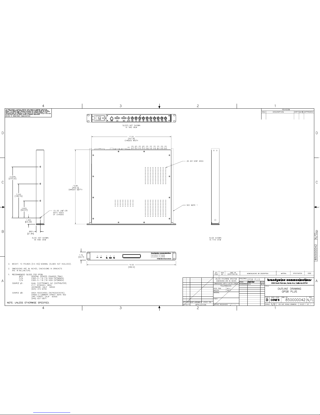
Page 83
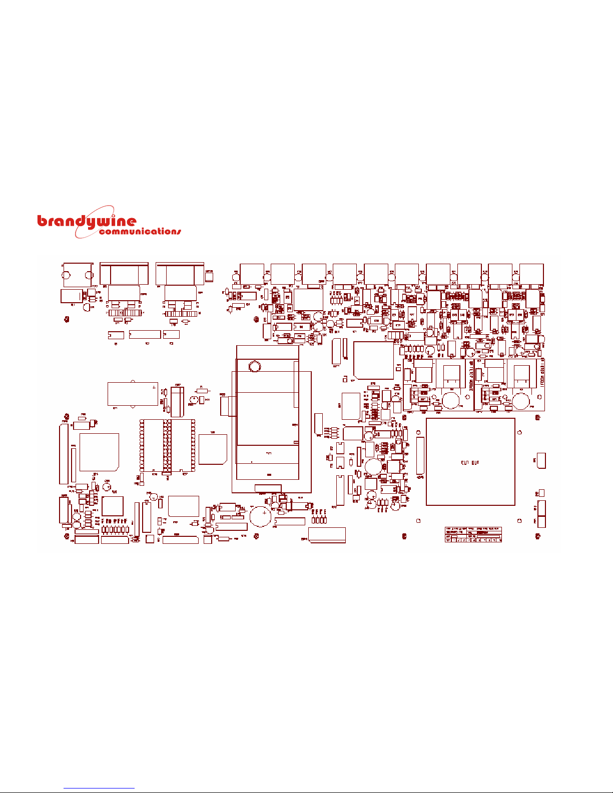
MANUAL P/N 900000007 REV 2.0
83
GPS8 Plus Link Locations
Page 84

MANUAL P/N 900000007 REV 2.0
84
Table of Link Settings 0180BN
Link ID Factory
Setting
Result Notes
LK1 OPEN NOT TESTING GPS8 Plus executes main program from flash memory; EPROM is still required
for key I/O management and ‘flash’ programming. Must be open to allow flash
programming.
LK1 1-2 TESTING FROM EPROM GPS8 Plus uses EPROM only; Flash need not be programmed.
LK2 OPEN NOT RESET Screwdriver reset pins.
LK3 1-2 WATCHDOG IS TRIGGERED BY
PROCESSOR
Jumper 2-3 to defeat watchdog during testing with emulator only.
LK4 OPEN NO TERMINATION Jumper fitted for RxD1 100R RS422 termination
LK5 OPEN VOLT FREE CONTACTS Jumper 1-2 for 0 V -> alarm open
Jumper 3-4 for +5 V -> alarm closed
LK6 OPEN NO TERMINATION Jumper fitted for RxD2 100R RS422 termination
LK7 1-2 and 3-4 50R OUTPUT Jumper 1-2 is 120R; Jumper 3-4 is 75R
LK8 2-3 10 MHz TCXO Bypasses Freq Doubler Jumper 1-2 for 10 MHz oscillator. See LK15.
LK9 OPEN T1 SELECT Jumper for E1 (2.048 MHz)
Fit appropriate VCXO at IC41
LK10 1-2 and 3-4 50R OUTPUT Jumper 1-2 is 120R; Jumper 3-4 is 75R
LK11 NOT FITTED NOT IN USE Option for LC/crystal selection if main PCB is fitted with bandpass filter (in place
of plug-in bandpass filter board).
LK12 NOT FITTED NOT IN USE As above
LK13 NOT FITTED NOT IN USE As above
LK14 NOT FITTED NOT IN USE As above
LK15 1-2 10 MHz TCXO Selects 10 MHz/2 for BP filter 5 MHz option
Link 2-3 to use the 5 MHz oscillator output directly if a 5 MHz oscillator is fitted.
LK16-19 (LK34) NOT FITTED NOT IN USE Option for frequency selection if main PCB is fitted with bandpass filter (in place
of plug-in bandpass filter board).
LK20-23 (LK35) NOT FITTED NOT IN USE As above
LK24 NOT FITTED NOT IN USE Programming voltage for GPS engine.
LK25-28 (LK36) LK25 Select square-wave output from SK8 (J5) as
PLL Synth (usually 2.048 MHz or 1.544 MHz)
The selections are PLL Synth, 1 MHz, 5 MHz, 10 MHz, or DDS Synthesizer.
LK29 OPEN NOT IN USE Can be read by the processor for option selection.
LK30-33 (LK37) LK30 Select square-wave output from SK10 (J6) as
PLL Synth (usually 2.048 MHz or 1.544 MHz)
The selections are PLL Synth, 1 MHz, 5 MHz, 10 MHz, or DDS Synthesizer.
Page 85
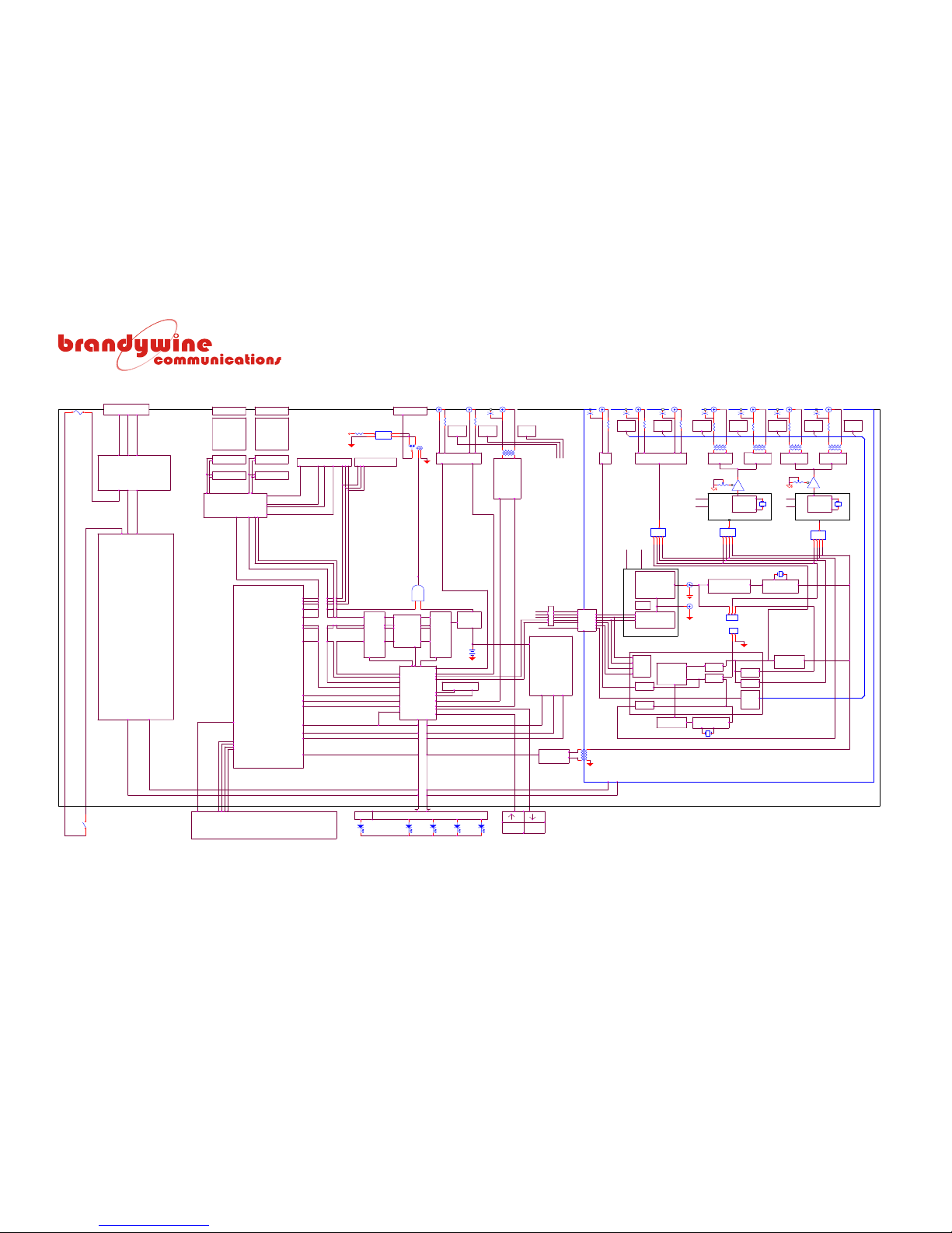
MANUAL P/N 900000007 REV 2.0
85
GPS8 Plus Block Diagram
T1/E1
BUFFER BUFFER
RAM
POWER
ENAB
TC1
+12V
50R
MODULATED
5MHz
CONTROL
1PPS
TTL ALARM
DIV 5
PROC FAIL
RS232/RS422 OUTPUTS
MONITOR
MICRO
SCLK
50R
FLASH
TXD2/RXD2
SRL
75R
FRQ1 SINE
1kHz
FD[1..7]
INPUT
TXD1/RXD1
AN[7..5]
GPS8 0180BD001
TxD
BSRDO
VCC
CONNECTOR
DIV 6
STATUS
OUTPUT
TO
/DACCS
75R
BOOT
DIN
T1/E1
EXT
SELECT
RS232
OR
RS422
ANALOGUE GROUND AREA
1kHz
COPYRIGHT TIME & FREQUENCY SOLUTIONS LTD 1998
5 WAY DIN
POWER
MONITOR
EPROM
16kHz
FD7
75R
ISOL
TO
1Hz
RCC 4497 BD
RUBIDIUM EFC
HZ1_OUT
TXD1/RXD1 PARAM
BP2 MODULE
OUTPUT
MICROCOMPUTER
FRAME
T1 OR E1
+/-3dB Output
Level Trim
N
50R
50R
OPTO
MONITOR
G703 SECTION 10 (set 3Vpp max sinewave into 75R)
LK?
LINK 5
123
4
5
DIV 2
E
6 INPUTS
MISC I/O (PARALLEL OP AND TI OUTPUTS)
FD2
DATA
MONITOR
OSC MODULE
10MHz (Digital)
SCLK
FILTER
FUSE
DIV 3
50R
PASS
16 BIT DAC
OUTPUT
REG
DIV 1
8 OUTPUTS
OP
RxD
+/-3dB Output
Level Trim
VALID
1
2
1MHz
FILTER
FD4
BUFFER
+12V
0V
MONITOR
SHIFT
OR 1/5/10MHz
SRDO
BUFFER
20 WAY HEADER
3 CTRL
PASS
FILTER
RxD
0V
1
2
3
ALARM
TC1_OUT
+15V
MICRO
5MHz
BENAB
PSU
FD1
50R
BP1 MODULE
OUTPUT
T1 OR E1
50R
FD6
10 WAY HEADER
BAND
OSCILLATOR
10MHz CRYSTAL
TxD
1kHz
COMPARATOR
2 LINE X 24 CHARACTER DISPLAY OPTION
OUTPUT
FROM
10MHz
+15V
CE
DIN
G703 SECTION 6 (2,37Vpp INTO 75R)
LK15
LINK 1
123
RV5
MONITOR
50R
8 WAY DIL SW
BUFFER
CRYSTAL DOUBLER
EPLD
LQ6
0V
50R
PHASE
10MHz CLK
MONITOR
DUART
AREA
ENT
0V
75R
FREQ1 SINE
POWER ON
SELECT
RS232
OR
RS422
12
34
120R
LK?
LINK 5
123
4
5
BUFFER
TO BUDGET FREQUENCY
LOGIC
LOOP
COMPARATOR
TYP
OUTPUT
9-WAY D
SO 222/1 DIGITAL AREA
LED DRIVER
AVAILABLE
DIV 4
TIMECODE
FILTER
ISOLATED SUPPLY
120R
SOURCE
600R
CONTROL
OUTPUT
OCXO
FILTER
10MHz
SEL
9-WAY D
TC2_OUT
TC1_OUT
TRACKED
MONITOR
TTL SQ WAVE into 50R
12.352MHz - T1
50R
50R
5MHz
MODULATOR
ADDR
POWER
MONITOR
L
HIGH PRECISION
VCO
50R
RS232 2)
LOW PHASE-NOISE
MICRO
SAT
TTL
OUTPUT
TTL SQ WAVE into 50R
LK?
LINK 5
123
4
5
16.384MHz - E1
OR 1/5/10MHz SINE 1Vrms into 50R
REF
CHOOSE
FD5
1Hz
DATA
CTRL
OUTPUT
0V
2
REF
ALARM
OPTION
RS232 (1)
1
RUBIDIUM
CODE
DIGITAL
MONITOR
8kHz FRAME
BLOCK DIAGRAM
SYNTHESISER
TIMECODE
OR
PULSES
MONITOR
DATA
E1/T1
COMPARATOR
POWER
TRANSFORMER
SRL
RV6
RS422 (2)
FREQ2 SINE
OPTION
REJECT
T1/E1
GPS ENGINE
OUTPUT
+12V
LQ5
UNMODULATED
1MHz
MICRO
REF_1PPS
VCO
CONTACTS
FD3
RS422 (1)
BAND
FRQ2 SINE
Page 86
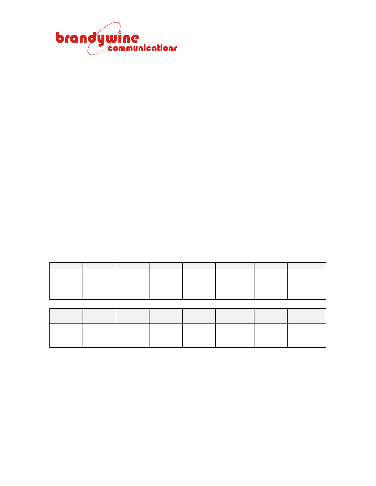
8 Appendix I Output Alarm Masks
The GPS8 Plus uses hardware detectors to measure the presence or absence of
its outputs. The detectors are monitored by the processor, which turns on the
red Fault LED and activates the alarm contacts in the event of an output failure.
The alarm sources can be ‘masked’ so that they no longer appear in the output
status record and no longer activate the front panel LED and alarm contacts.
This may be necessary if an output is not in use or if a particular output has been
customized for an application and the hardware detector indicates a permanent
alarm condition.
The output alarms are shown in two status bytes that can be seen in field 7 of the
response to the query a<CR>LF>. Any alarm source that is active will set a ‘1’ in
its corresponding status bit and four bits are indicated by the hexadecimal value
of each character in field 7. For example, the response message is as follows:
Field 7
$PRCCG, A, 018, 10:27:03, 17/12/01, 4, 0, 1, 0003, 80*2C<cr><lf>
Field 7 in the example has BIT 0 and BIT 1 set. The bit descriptions are shown
in the tables below.
BIT 15 BIT 14 BIT 13 BIT 12 BIT 11 BIT 10 BIT 9 BIT 8
Reserved Reserved Reserved Reserved Reserved Digital time
J10 (SK4) J9 (CON8) J8 (SK3)
code pulse fail
BIT 7 BIT 6 BIT 5 BIT 4 BIT 3 BI T 2 BIT 1 BIT 0
Synthesiser
PLL
unlocked
J7 (SK12) J6 (SK10) J5 (SK8) J4 (SK9) J3 (SK11) J2 (SK7) J1 (SK6)
8 KHz
frame fail
Frequency
square fail
Frequency
square fail
Frequency
sine 2 fail
Frequency
sine 2 fail
The unit has no sine 1 frequency output on J1 and J2 due to the removal of an
internal band-pass filter module.
1 PPS fail Modulated
Frequency
sine 1 fail
time code
fail
(LSB)
Frequency
sine 1 fail
86
MANUAL P/N 900000007 REV 2.0
Page 87
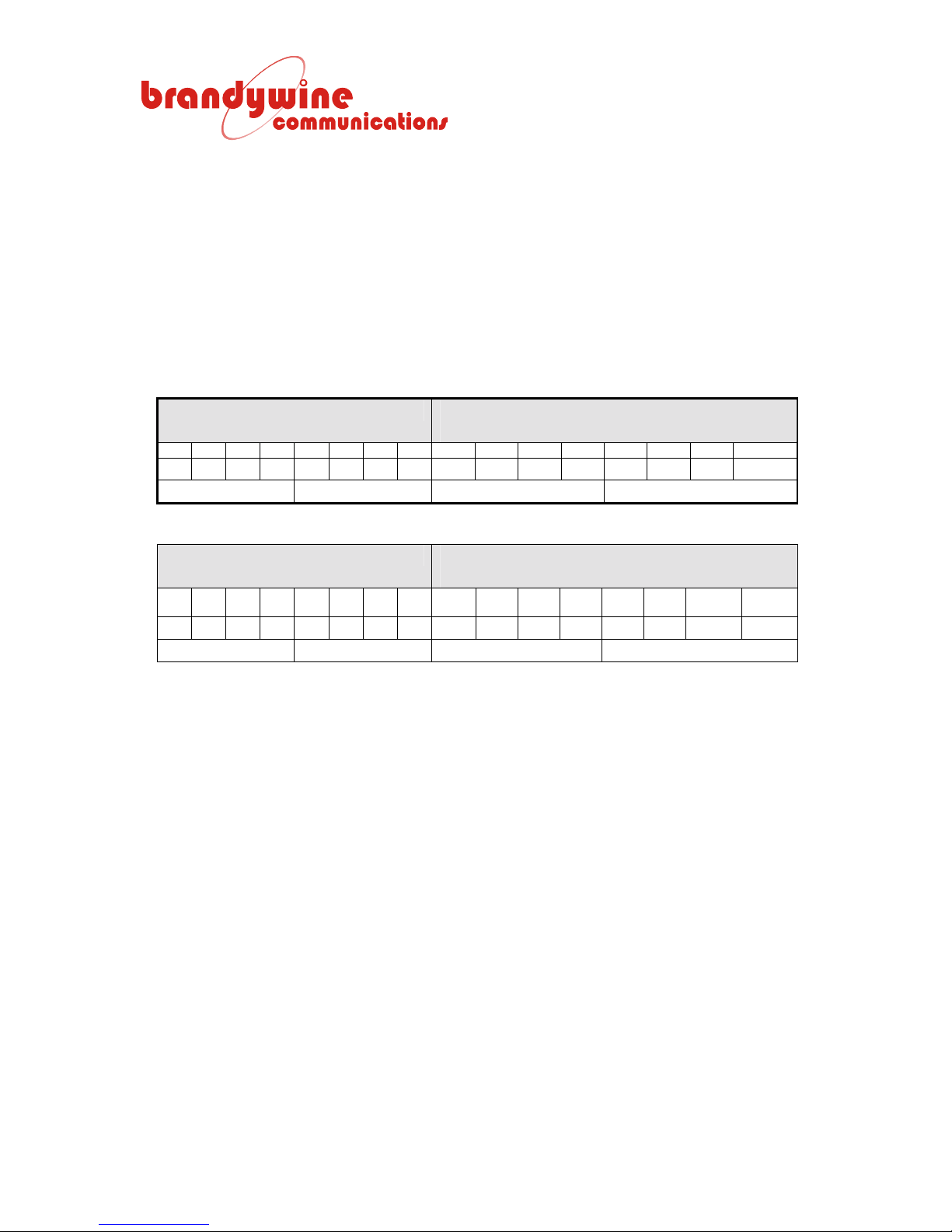
The alarm masks are contained in two bytes corresponding to the 16 bits in the
table above. Each byte is stored as its true value, where ‘1’ means the alarm is
enabled and its complement (all bits inverted) in EEPROM at address 4 and 5.
There are 16 bits of data at each of these addresses and the masks are
organized as F1MSK and its complement at address 4 and F2MSK and its
complement at address 5. F1MSK contains the bits to mask BIT 0 through BIT 7
of the alarm bytes and F2MSK contains the bits to mask BIT 8 through BIT 15.
The complement byte is used for protection. If the value does not agree with the
true value as to which bits should be masked, then the default values are loaded
(no masks are applied). To change the mask value it is easiest to prepare a
table as shown for the example below.
F1MSK CHECK BYTE F1MSK BYTE SHOWING
CORRESPONDING ALARM BIT NO
BIT7 BIT6 BIT5 BIT4 BIT3 BIT2 BIT1 BIT0
0 0 0 0 1 1 1 1 1 1 1 1 0 0 0 0
0 F F 0
Table 26 F1MSK at EEPROM Address 04 with All Four Sine Wave Output Alarms Disabled
F1MSK CHECK BYTE F1MSK BYTE SHOWING
CORRESPONDING ALARM BIT #
BIT
15
BIT
14
BIT
13
BIT
12
BIT
11
BIT
BIT9 BIT8
10
0 0 0 0 0 0 1 0 1 1 1 1 1 1 0 1
0 2 F D
Table 27 F2MSK at EEPROM Address 05 with 1 PPS Output Alarm Disabled
To enter the new values the <CTRL T> 6 Edit/View EEPROM menu is used.
Enter <CTRL T>
Tests
1. PWM u/U d/D
2. A-D1; D-A1 u/U OR d/D
3. DAC u/U d/D H C L W
4. Delay Adjust
5. Sounder
6. Edit/View EEPROM
7. Reset NVRAM & RE-START
8. PLL Op 0-6, 7 Trace RS, 8 Frq Meas
9. More Tests
87
MANUAL P/N 900000007 REV 2.0
Page 88

Press 6
6. Edit/View EEPROM
<SPACE> Display All EEPROM
F TxD2 Format 1 to 3
O Enter Osc 0 to 9
P Program EEPROM location
U Unlock
P Program EEPROM location
Press P (must be uppercase P)
Enter Hex Addr (ESC=quit) 00-37
Enter 4<RETURN>
4 Addr=04
Enter Hex Data 0000-FFFF
Enter 0FF0<RETURN>
0FF0 Data=0FF0
GPS8 Plus confirms location has been programmed
Prog time=02ms Value Saved=0FF0
P Program EEPROM location
Enter Hex Addr (ESC=quit) 00-37
User can just press <RETURN> for the next address
Addr=05
Enter Hex Data 0000-FFFF
User enters 02FD<RETURN>
02FD Data=02FD
Prog time=02ms Value Saved=02FD
P Program EEPROM location
Enter Hex Addr (ESC=quit) 00-37
88
MANUAL P/N 900000007 REV 2.0
Page 89

Press <ESC> to quit programming function of the EEPROM menu
6. Edit/View EEPROM
<SPACE> Display All EEPROM
F TxD2 Format 1 to 3
O Enter Osc 0 to 9
P Program EEPROM location
U Unlock
PRESS <ESC> again to quit test menu
QUIT 6
For the new values to take effect the unit must be powered on again. Note that
the initialization messages include a description of the alarm masks showing ‘0’
for alarm outputs that are disabled and ‘1’ for alarm outputs that are enabled.
L=load ESC=RUN.....
Initialize - Clear RAM
Initialize DUART
TFS Ltd C Fri Dec 14 2001 17:08
[email protected]
Testing IC27 RAM......IC27 RAM PASSED
Test IC27 NV_RAM Contents.IC27 PASSED - Using RAM based Parameters
Testing IC28 ROM......IC28 ROM PASSED Cksum = 5074
Test Alarm ON then OFF
Testing Indicators.......
Osc is XTAL4 OSA 8410 TCXO...Calibration Found
Initialize PLL...PLL Initialized Slope Positive
TC1=AFNOR TC2=Pulse
Pulse 1 msg: $PRCCG,C,U000000,+100*65
Pulse 2 msg: $PRCCG,K,UXXXX00,+100*6D
TimCod msg : $PRCCG,E,5,2,2,2*2B
Offset msg : $PRCCG,O,U,+00:00*62
Alarm Masks
1234 5678 1234 5678
0000 1111 1011 1111
Set Timers
Run GPS8 EGPS18
Enter A<RETURN><CTRL J>
To see the value reported in field 7 of the status message
$PRCCG,A,018,13:28:21,17/12/01,8,2,1,0000,00*25<cr><lf>
89
MANUAL P/N 900000007 REV 2.0
Page 90
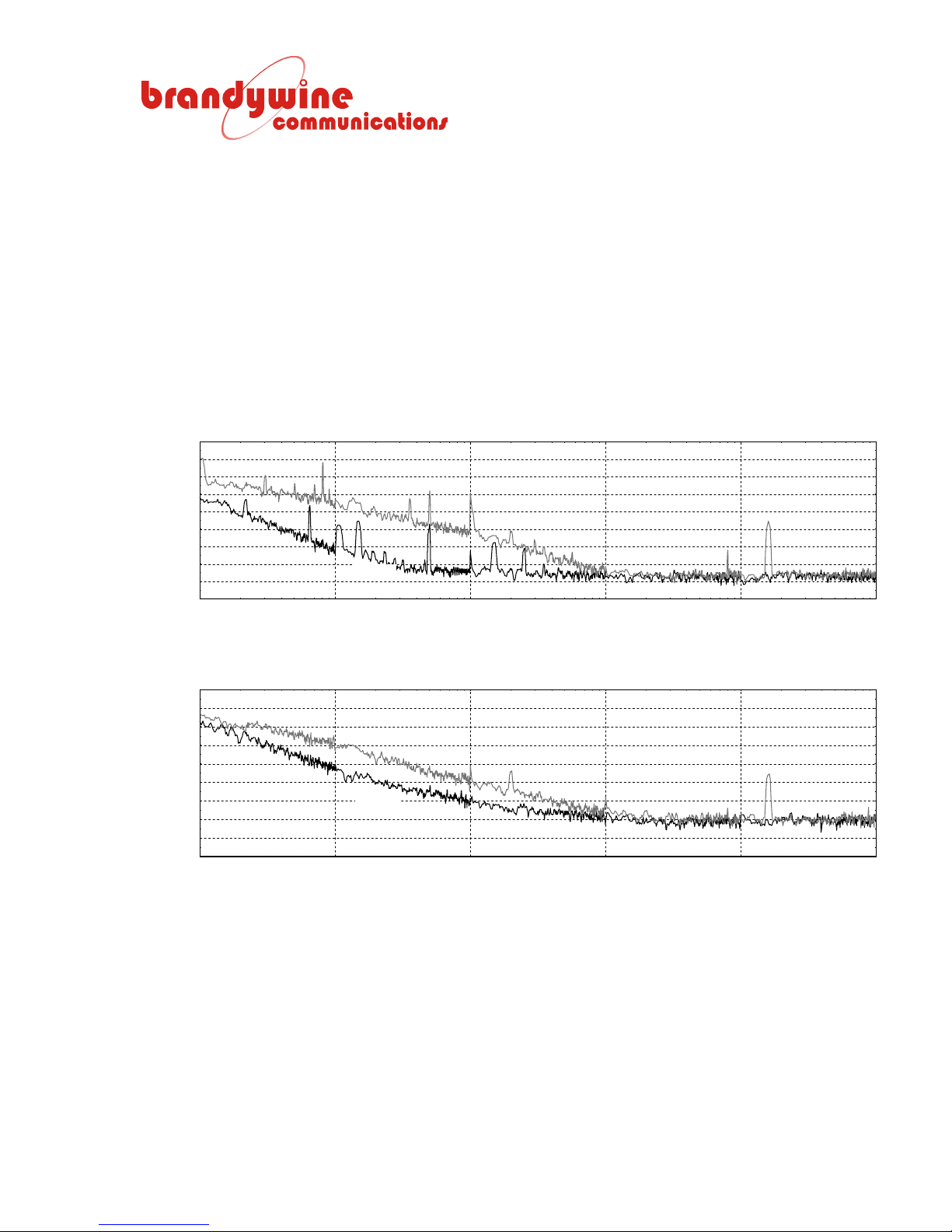
9 Appendix II Phase Noise
The standard GPS has been designed for low phase noise. The precision
ovened crystal oscillator and the analog distribution is separately powered and
opto-isolated from the digital processor section. However, the standard unit with
telecom outputs shows some expected cross-talk between the telecom outputs
and the standard frequency outputs, primarily visible in the form of a substantial
peak at 16 KHz in the phase-noise spectrum. One solution is to disable the
telecom frequency synthesizer for applications that do not require the telecom
outputs. All the phase noise plots were taken while the units were disciplining.
GPS8 AND GPS8LN PHASE NOISE - 5MHz OUTPUTS
-80
-90
-100
-110
-120
-130
-140
-150
-160
-170
0
10
Single Sideband Phase Noise £(f) dBc
10
GPS8
GPS8LN
1
2
10
Frequency
3
10
4
10
5
10
Single Sideband Phase Noise £(f) dBc
-80
-90
-100
-110
-120
-130
-140
-150
-160
-170
10
GPS8 AND GPS8LN PHASE NOISE - 10MHz OUTPUTS
GPS8
GPS8LN
0
1
10
10
2
Frequency
10
3
10
4
10
5
90
MANUAL P/N 900000007 REV 2.0
 Loading...