

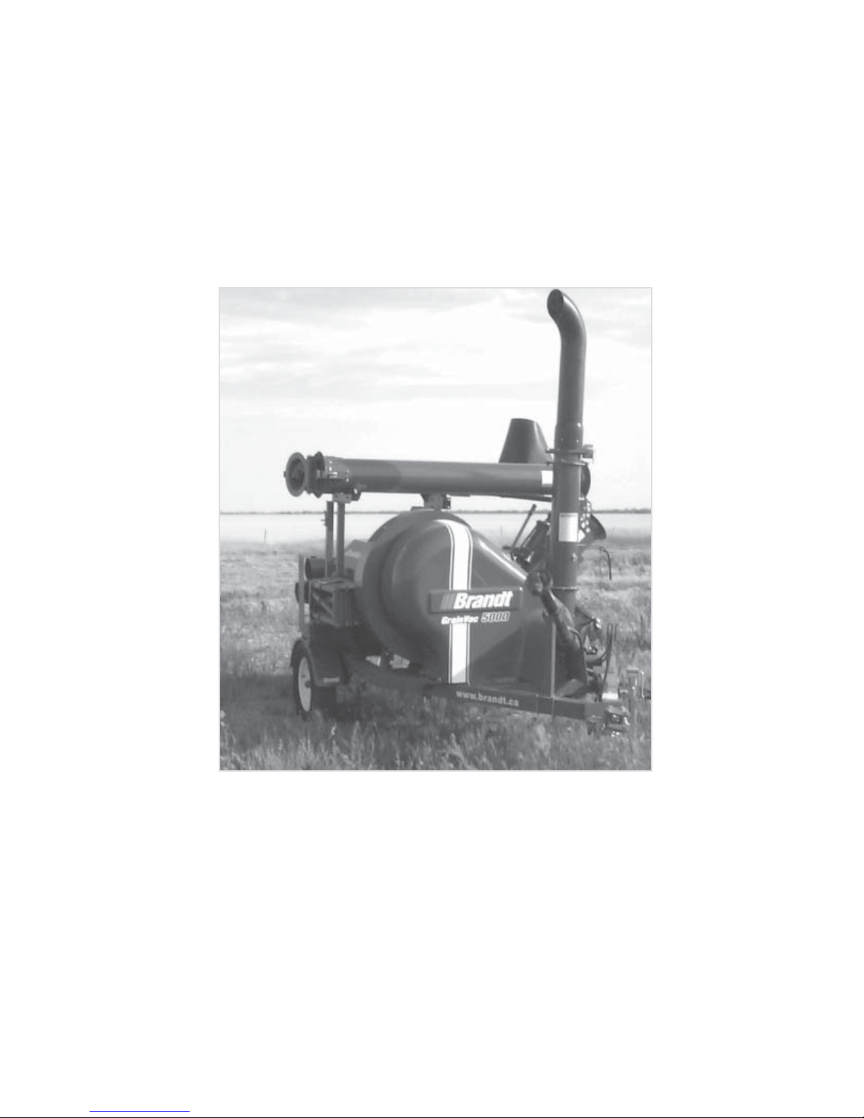
Brandt GRAIN VAC 5000, GRAIN VAC 5000 EX Operator And Parts Manual

GRAIN VAC
5000
5000 EX
OPERATORS
AND PARTS
Part No. B012352 Rev 15 Effective Jan., 2007
MANUAL

BRANDT WARRANTY POLICIES AND PROCEDURES -
effective May 1, 2001.
Introduction To The Warranty Policy
At Brandt Agricultural Products Ltd. (“Brandt”), it is our goal to ‘Deliver Value’ by providing you with innovative,
high-quality, trouble-free products. While we continually find new ways to improve our design and manufacturing
processes, it is unreasonable to expect flawless performance from all machines at all times. Brandt’s warranty
policy is in place to protect the end user from product defects.
Brandt will warranty each new Grain Vac 5000 to be free from factory defect in material and workmanship
under normal use and service, when operated in accordance with Brandt factory instructions as contained in
this operator’s manual, for
original purchaser. Warranty is available to the original purchaser only and is not transferable. Any equipment
that is purchased for use by commercial business operations, rental applications, or hired out on a
custom basis will be eligible for 6 months parts and labour only. The warranty term for any products
used by Brandt for demonstration purposes or Brandt product that has been reworked and sold through
Brandt’s factory will carry a 6 months parts only warranty.
Brandt will reimburse factory-authorized dealers for warrantable parts and labour for one full year from date of
delivery, and will cover warrantable parts only during the second year. Brandt’s warranty does not cover and
Brandt shall not be responsible for costs incurred in connection with repairs made outside the periods specified
in the immediately preceding sentence or for repairs made by unauthorized persons. Brandt’s obligation under
this warranty is limited to the repairing of, or supplying of replacement parts in exchange for, any parts that are
defective due to factory workmanship or material. Brandt makes no warranty as to tires, cylinders, power
take off shafts, belts, hoses or any accessories which are not manufactured by Brandt but that may be sold
along with Brandt products, as all such accessories are covered by the manufacturer’s own warranty. This
warranty is void on any unit that has been tampered with or that has been subject to misuse, neglect, accident
or which has had the serial number tampered with or removed.
two years on parts, one year on labour from the date of delivery to the
Responsibility for Providing Warranty:
• It is the customer’s responsibility to return the machine to the dealership for warranty repair or pay the
dealership call out fees.
• It is the Dealer’s responsibility to provide warranty service to the end user with support to be provided
by Brandt in accordance with this policy.
• All claims for warranty must be presented to Brandt by the Dealer and not the end user.
• The Dealer will be responsible for any warranty given by it, without the prior authorization of Brandt.
• Brandt will support our Dealers in providing this warranty service through ongoing training and
knowledgeable support staff.
• The cost to the Dealer of providing warranty service in accordance with this policy will be reimbursed
by Brandt to cover parts, labor and freight as per our published Warranty Claim Procedure.

Warranty Registration and Pre-Delivery Inspection Forms
• The Dealer must complete and send to Brandt a Warranty Registration form for each new Brandt
Product sold by the Dealer, within 30 days of delivery to customer, to ensure that the machine is
eligible for warranty. Warranty Registrations must be accompanied by a completed and signed PreDelivery Inspection (PDI) form which is filled out upon completion of the Pre-Delivery Inspection at
time of sale. Machines that do not have Warranty Registration and a copy of the PDI forms registered
on file with Brandt will not receive any warranty labor or parts compensation until such documents are
completed and filed with Brandt. Triplicate copies of the Warranty Registration as well as the PreDelivery Inspection forms are included inside the Operator’s Manual supplied with each Brandt Product.
Warranty Policy Definitions
• “Free from Defects in Material and Workmanship”
A failure of a part caused by the part itself with no abnormal external influences is a defect. An example
would be a hydraulic hose that has been shipped from the Brandt factory with a pin hole leak.
A failure caused by abnormal external force acting on a part is not a defect. For example, an auger
flight bent or broken by a rock picked up while cleaning grain off the ground is not considered defective.
• “Normal Use and Service”
Each product from Brandt has an intended use which is advertised through our brochures and videos.
A failure occurring due to an unusual condition or operation not specifically represented by Brandt will
not be warranted.
• “Operated in Accordance with Factory Instructions”
The Operator’s Manual supplied with each Brandt Product gives instructions on safe, optimal, productive
operation of the machine. Shortcuts in operation or disregard for these instructions may cause damage
to the unit, which will not be warranted.
Failure caused by misuse, accident or by a lack of required normal maintenance as specified in the
Operator’s manual will void warranty. Damage as a result of accident or shipping would not be
considered a defect and therefore not warrantable. Failures due to improper adjustment not checked
on the pre-delivery inspection are not considered defects.
THE EXPRESS WARRANTIES OUTLINED ARE EXCLUSIVE AND IN LIEU OF ALL
OTHER WARRANTIES, CONDITIONS AND TERMS AS TO QUALITY, FITNESS OR
PERFORMANCE OF THE GOODS, WRITTEN, ORAL OR IMPLIED, STATUTORY OR
OTHERWISE, INCLUDING, WITHOUT LIMITATION, ANY WARRANTIES OR
CONDITIONS OF MERCHANTABILITY OR FITNESS FOR A PARTICULAR PURPOSE,
AND ALL SUCH OTHER WARRANTIES, CONDITIONS AND TERMS ARE HEREBY
DISCLAIMED AND EXCLUDED.

The Customer’s sole and exclusive remedy with respect to the quality, performance or fitness of the product
shall be as provided in the express warranties described above and Brandt shall have no liability with respect
to any non-conformance of or defect whatsoever in the product (including any liability for direct, indirect,
special, incidental or consequential damages) whether in warranty, contract, tort, negligence, strict liability or
otherwise. The Customer shall not return the product to Brandt or incur any shipping or other charges in
respect of the product without Brandt’s prior written consent.
PRODUCT IS INELIGIBLE FOR WARRANTY IF NOT REGISTERED

Brandt Agricultural Products Ltd.
BOX 317 STATION MAIN
TH
AVE. AND PINKIE ROAD
13
REGINA, SASK., S4P 3A1
WARRANTY REGISTRATION FORM
Please Print Clearly
This form must be filled out by the dealer and signed by both the dealer and the customer at the time of delivery.
Customer Name Dealer Number
Customer Address Dealer Name
City Prov/State Dealer Address
Postal / Zip Code Area Code Phone Number City Prov/State
E-Mail Address Postal / Zip Code Area Code Phone Number
Delivery Date: E-Mail Address
Purchase Date:
Serial Number:
PRODUCT
______Standard Augers Model No. ___________
______
Supercharged Auger Model No. ___________
______
Direct Drive Auger Model No. ___________
______
Swing Away Auger Model No. ___________
______
Utility Auger Length______ Diameter _____
______Tailgate
______Trakker _____________ ______________
Make
Diameter & Length
_____Belt Conveyor Model No. _________________
Drive Type _____________ Intake Type ____________
1. I have performed the predelivery inspection procedure, as set out on the predelivery inspection sheet in
the operators manual and I am satisfied the above described machine is setup and adjusted properly.
2. I have thoroughly instructed the buyer on the above described equipment which included review of the
Operators Manual content, equipment care, adjustments, safe operation and applicable warranty policy.
Date:_____________________ Dealer’s Signature: ________________________________________
I have received the Operators Manual for the above described machine and I have been thoroughly
instructed on, and understand, the care, the adjustments, and the safe operation of the above described
machine and applicable warranty policy.
_____ QF 1500 Sprayer Boom Size _____
_____
QF 2500 Sprayer Boom Size _____
_____
QF 2500S Sprayer Boom Size _____
_____
3PT Sprayer ____ 70 Gal. _____ 130 Gal.
_____ SB 4000 Sprayer Boom Size _____
_____ Heavy Harrow Width ______ Tine Diameter ______
_____ Grain Vac Model No. __________
_____ Bale Processor
Date: _____________________ Owner’s Signature: _______________________________________
White Copy - Brandt Yellow Copy - Dealer Pink Copy - Customer

PREDELIVERY CHECKLIST
GRAIN VAC 5000 Serial # Date
1. The PTO shaft and the storage post have been installed as per instructions in the Operator’s
Manual, sec. 1.1, page 10.
2. The wheels have been moved to the outermost position as per the instructions in the Operator’s
Manual, sec. 1.2, page 10.
3. The hitch clevis plate is installed in the lower most position and the hose holder is vertical as per the
instructions in the Operator’s Manual, sec. 1.3, page 11.
4. The fan drive pulleys are aligned and the fan drive belt is tensioned so the idler spring is compressed
to 2 3/4” as per the instructions in the Operator’s Manual, sec. 5.1, page 35.
5. The auger drive sprockets are aligned and the drive chain tension is adjusted to allow one chain
thickness movement as shown in the Operator’s Manual, sec. 5.4, page 37.
6. Check to insure the gearbox is half full of oil by inserting a clean dip stick into the upper vent plug.
7. Check the wheel bearings to ensure they have the correct preload, no slop and no excessive
grease leakage at the seals.
8. Lubricate all grease points as shown in the Operator’s Manual, sec. 4, page 33.
9. Check the air pressure in the tires. Inflate to 35 lbs. psi.
10. Check the tightness of the wheels bolts. Tighten to 90 ft.lbs. torque.
11. Remove the locking device as per page 23 , connect the hydraulic hoses to a tractor and cycle the
auger from transport position to fully extended and back to check for hydraulic oil leaks and hose
routing problems. Fix any problems at this time.
12. Extend the auger to the fully extended position and check the tie rod adjustment as per the instructions
in the Operator’s Manual, sec. 5.11, page 41.
13. Open the upper body and check the positioning of the chaffers. The upper chaffer’s holes should
be facing the rear of the machine and the lower chaffer’s holes should be facing the front of the
machine. See sec. 5.12, page 43 in the Operator’s manual for information.
14. Connect the PTO Shaft to the tractor, rotate the tubes into working position and do the clutch run-
in procedure as described in Section 5.18, page 56. Run at operational speed for 10 minutes to
ensure the machine runs smoothly without any unusual noise or vibration.
15. Lower the plastic Exhaust Stack into transport position and replace the tube locking pin.
5

Contents
Predelivery Checklist ............................................................................................................ 5
Section 1 - Introduction ........................................................................................................ 9
1.1 PTO Post Installation ....................................................................................... 10
1.2 Trailer Wheel Mounting.................................................................................... 10
1.3 Hitch Clevis .................................................................................................... 11
1.4 Pail Hook ........................................................................................................ 11
1.5 PTO Clutch Run-In Procedure ......................................................................... 11
Section 2 - Safety ................................................................................................... 12
2.1 General Safety .................................................................................................. 13
2.2 Operating Safety .............................................................................................. 13
2.3 Maintenance Safety ......................................................................................... 14
2.4 Transport Safety .............................................................................................. 14
2.5 Grain Bin Safety .............................................................................................. 14
2.6 Safety Decals .................................................................................................. 14
2.7 Sign Off Form ................................................................................................. 15
2.8 Safety Decal Locations .................................................................................... 16
Section 3 - Operation ......................................................................................................... 19
3.1 Principles of Operation .................................................................................... 19
3.2 First Operation ................................................................................................ 20
3.3 Pre-Operation Checklist .................................................................................. 20
3.4 Equipment Matching ........................................................................................ 21
3.5 Attaching / Unhooking ...................................................................................... 21
A. To Hook to a Tractor ............................................................................ 21
B. To Hook to a Truck .............................................................................. 22
3.6 Setup For Operation ....................................................................................... 23
3.7 Operation ........................................................................................................ 23
A. General Operating Instructions .............................................................. 23
B. Full Bin Unload ..................................................................................... 24
C. Removing Grain from in a Clean Up Operation ...................................... 25
D. Optional Adjustable Height Bin Snake .................................................... 26
E. Adjustable Air Throttle and Vent ............................................................. 27
F. Folding Exhaust Deflector ....................................................................... 29
3.8 Shutdown ........................................................................................................ 29
3.9 Operation Hints ............................................................................................... 30
3.10 Soybean / Field Pea Operation ...................................................................... 30
3.11 Expected Capacities for Various Crops ........................................................... 31
3.12 Transporting .................................................................................................. 31
3.13 Storage ......................................................................................................... 32
Section 4 - Service .............................................................................................................33
4.1 Fluids and Lubricants ....................................................................................... 33
4.2 Lubrication ...................................................................................................... 33
4.3 Service Intervals .............................................................................................. 34
4.4 Service Record ................................................................................................ 34
6

Section 5 - Maintenance ..................................................................................................... 35
5.1 Fan Drive Belt Tension .................................................................................... 35
5.2 Fan Belt Replacement ..................................................................................... 35
5.3 Drive Pulley Alignment .................................................................................... 36
5.4 Auger Chain Drive .......................................................................................... 37
5.5 Airlock Plates ................................................................................................. 38
5.6 Auger Shear Bolt ............................................................................................ 38
5.7 Fan Bearing Box ............................................................................................. 39
5.8 Drive Shaft Bearings ....................................................................................... 40
5.9 Gearbox Removal ........................................................................................... 41
5.10 Suction Hoses ............................................................................................... 41
A. Clamp Adjustment: ................................................................................ 41
B. Hose / Clamp Replacement ................................................................... 41
5.11 Auger Fold Tie Rod ....................................................................................... 41
5.12 Chaffer Orientation ........................................................................................ 43
5.13 Air Throttle Function ...................................................................................... 44
5.14 Fan Rotor and Housing Inspection ................................................................. 45
5.15 Fan Rotor and Bearing Box Replacement ....................................................... 47
5.15.1 If the Fan is Rubbing ....................................................................... 48
5.15.2 Replacing the Fan Rotor ................................................................. 49
5.15.3 Replacing the Fan Rotor and Bearing Box ....................................... 50
5.16 Auger Flight Installation and Adjustment ......................................................... 52
5.16.1 Auger Flight Installation and Adjustment - Model 5000 ................... 52
5.16.2 Auger Flight Installation and Adjustment - Model 5000 EX ............. 54
5.17 Tube Lock Spring Adjustment ........................................................................ 55
5.18 PTO Clutch Assembly & Run-In Instructions .................................................. 56
5.19 PTO Shaft Slip Clutch Assembly .................................................................... 57
Section 6 - Trouble Shooting ............................................................................................... 58
Section 7 - Specifications .................................................................................................... 63
7.1 Mechanical ...................................................................................................... 63
7.2 Bolt Torque ..................................................................................................... 64
Section 8 - Parts Listing ......................... ...........................................................................P-1
Model Number Serial Number
Serial Number Location
7

This page is blank.
8
Section 1 - Introduction
CONGRATULATIONS on your choice of a Brandt Grain Vac 5000.
Use this manual as your first source of information about the machine. If you follow the instructions given
in this manual, your Grain Vac will work well for many years.
Safe, efficient, and trouble free operation of your Grain Vac requires that you and anyone else who will be
operating or maintaining the machine, read and understand the Safety, Operation, Maintenance and Trouble
Shooting information within the Operator’s Manual.
This manual covers the Brandt Grain Vac model 5000 and 5000 EX, manufactured by Brandt Agricultural
Products Ltd.
Keep this manual handy for frequent reference and to pass on to new operators or owners. Call your
Brandt dealer if you need assistance or information.
OPERATOR ORIENTATION - The directions left, right, front and rear, as mentioned throughout the
manual, are as seen from the tractors driver’s seat facing in the direction of travel.
9
1.1 PTO Post Installation
Before using the Brandt Grain Vac the PTO Post
must be installed. The Post and the tractor end of
the PTO shaft are bundled together and placed inside
the vac body. The following instructions will help
with the installation of the PTO Holder.
1. Loosely attach the PTO post to the front right
side of the frame, see photo below, with the two
5/16” x 4” ubolts and 5/16” locknuts.
2. Slide the implement end of the PTO shaft into
the half mounted to the vac.
3. Grease the universal joints on both ends of the
PTO shaft. Grease the middle or telescoping
part of the PTO shaft.
4. Set the PTO shaft onto the PTO holder
assembled above.
6. Tighten the nuts on the PTO holder U-bolts.
7. Install the PTO holder pin onto the top of the
PTO holder. This will secure the PTO shaft.
1.2 Trailer Wheel Mounting.
Before using the Brandt Grain Vac, the transport
wheels must be moved to the outer (working)
position as shown below.
1. Place a jack under the frame of the Vac and
raise one wheel off the ground.
5. Slide the PTO holder as far back as possible
without the PTO shaft interfering with the fan
guard. Mounting the post farther back reduces
the chance of the PTO shaft interfering with a
towing vehicle.
2. Remove the four 1/2” x 1 3/4” hex bolts, and
the 1/2” locknuts.
3. Position the wheel and fender assembly in the
outer (working) position. Note that it is not
necessary to remove the fender first.
4. Fasten in place with the hardware removed in
step 1 above.
5. Repeat the procedure on the other wheel.
10
Transport
Position
Working
Position
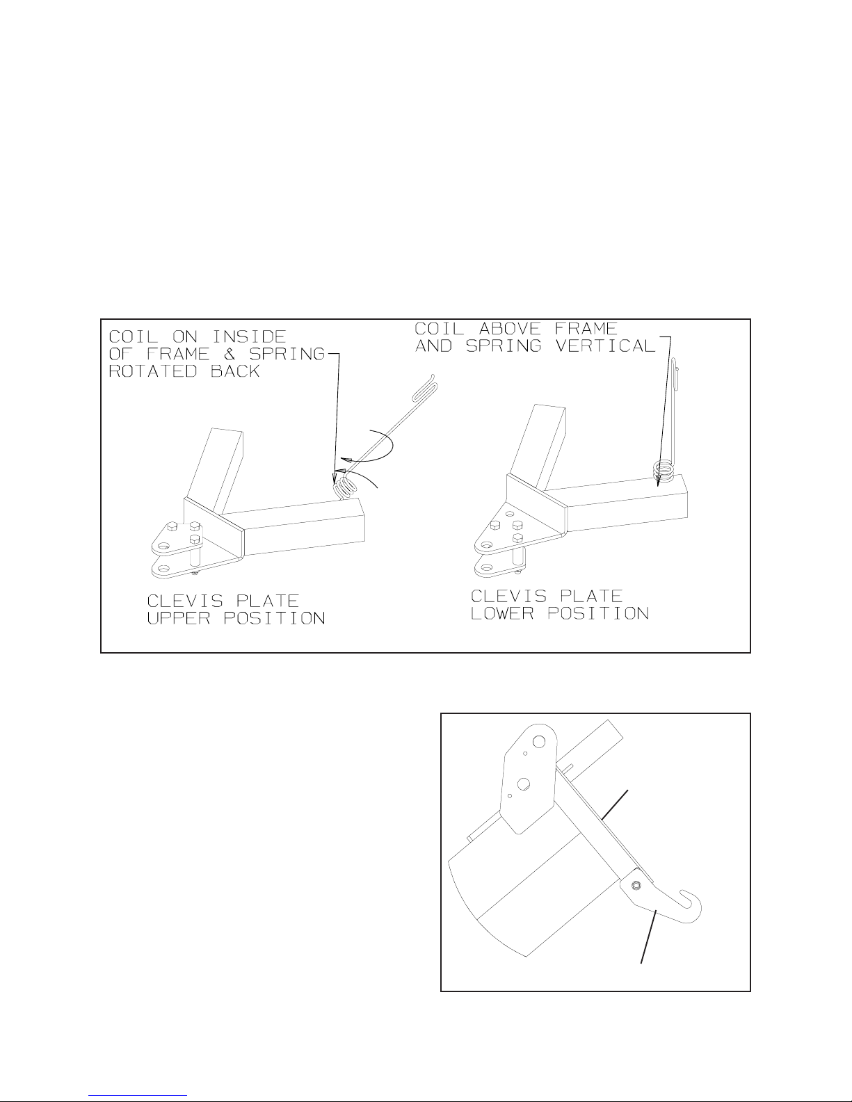
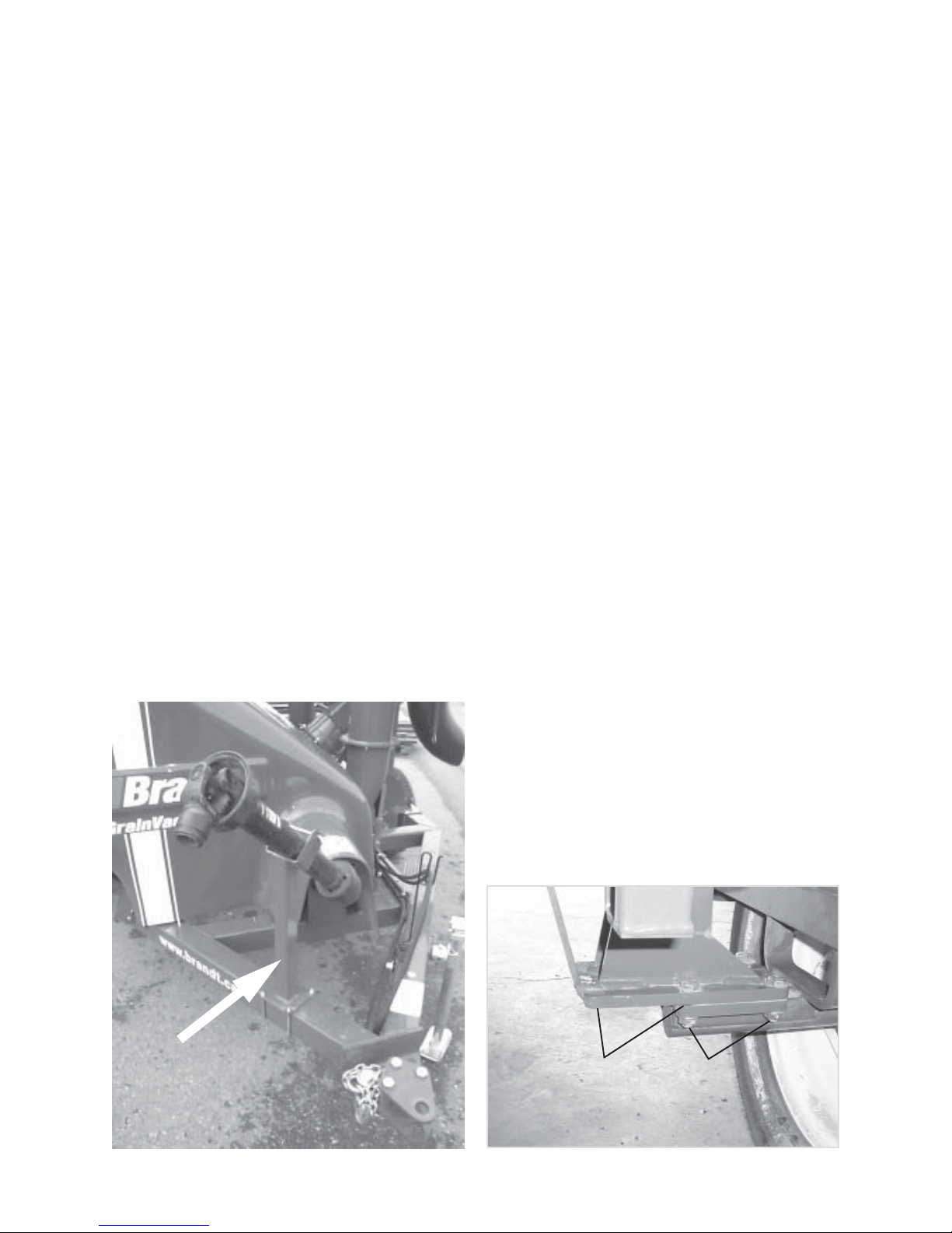
1.3 Hitch Clevis
The hitch clevis plate has been installed in the top
position for shipping and it should be relocated to
the lower working position before delivering to the
customer. As shown in the figure below, remove
the 3/4” locknuts, spacer tubes, and hitch plate and
re-install in the lower position.
In addition, the hose holder spring has been installed
inside out and rotated back. Remove the spring
retainer nut, pull off the spring and flip inside out so
that the coil is laying above the frame member.
Reinstall the retaining nut and secure with the spring
in the vertical position.
1.4 Pail Hook
The Pail Hook has been installed in the stowed
position for shipping and it should be relocated to
the working position before delivering to the customer.
As shown in the adjacent figure, remove the 3/8”
locknut and re-install in the working position.
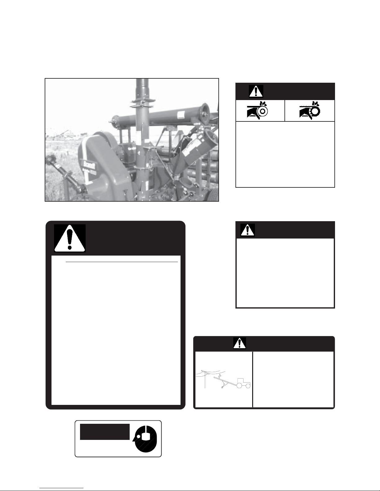
1.5 PTO Clutch Run- In Procedure
The Clutch on the PTO Shaft has a run-in procedure
that is required to be done before the vac is put to
use. Refer to Section 5.18, page 56 of this manual
for the run-in instructions.
Transport Position
Lower Tube
Rotate the Pail Hook into working position
11

Section 2 - Safety
SAFETY ALERT SYMBOL
Watch This Symbol. It Points Out important precautions.
It Means “ATTENTION — Become Alert!
Your Safety Is Involved.”
Occupational safety is of prime concern to Brandt Agricultural Products Ltd. This Grain Vac Manual was
written with the safety of the operator and others who come in contact with the equipment as our prime
concern. The manual presents some of the day to day work problems encountered by the operator and
other personnel. We wrote this manual to help you understand safe operation procedures for our Grain
Vac. We want you as our partner in the safe operation of our equipment.
It is your responsibility as an owner or operator or supervisor, to know what specific requirements,
precautions and work hazards exist and to make these known to all other personnel working with the
equipment or in the area, so that they too may take any necessary safety precautions that may be required.
Failure to read this Grain Vac Manual and its Safety Instructions is a misuse of the equipment.
THREE WORDS USED IN CONJUNCTION WITH THE SAFETY ALERT SYMBOL
DANGER!
WARNING!
Tells you that a hazard exists which would result in a
high probability of death or serious injury if proper
precautions are not taken.
Tells you that a hazard exists which can result in injury
or death if proper precautions are not taken.
CAUTION!
Tells you to remember safety practices, or directs
attention to unsafe practices which could result in
personal injury if proper precautions are not taken.
12

2.1 General Safety
1. Read and understand the Operator’s manual and
all safety signs before operating, maintaining,
adjusting or unplugging the Grain Vac.
2. Grain Vac owners must give operating
instructions to operators or employees before
allowing them to operate the machine, and at
least annually thereafter per OSHA
(Occupational Safety and Health Administration)
regulation 1928.57.
3. The most important safety device on this machine
is a SAFE operator. It is the operator’s
responsibility to read and understand all safety
and operating instructions in the manual and to
follow them. All accidents can be avoided.
4. A person who has not read and understood all
operating and safety instructions is not qualified
to operate the machine. An untrained operator
exposes himself and bystanders to possible
serious injury or death.
10. Place all controls in neutral, stop the engine, set
park brake, remove ignition key, and wait for
all moving parts have come to a complete stop
before servicing, adjusting, repairing or
unplugging.
11. Know where overhead electrical lines are
located and stay away from them. Electrocution
can occur without direct contact.
12. Think Safety! Work Safely!
2.2 Operating Safety
1. Ensure all guards are in place and in good repair
before operating.
2. Keep hands, feet, hair and clothing away from
all moving or rotating parts, including the suction
inlet and the clean out door situated under the
vac body.
5. Do not modify the equipment in any way.
Unauthorized modification may impair the
function and/or safety and could affect the life
of the equipment.
6. Have a first-aid kit available for use should the
need arise and know how to use it.
7. Provide a fire extinguisher for use in case of a
fire. Store in a highly visible place.
8. Do not allow riders on the machine.
9. Wear appropriate protective gear. This list
includes but is not limited to:
-hard hat
-protective shoes
-protective goggles
-heavy gloves
-wet weather gear
-hearing protection
-respirator or filter mask
3. Clear the area of all bystanders, especially
children, before starting.
4. Attach securely to tractor using a retainer on
drawbar pin and a safety chain.
5. Be sure the PTO driveline guard telescopes and
rotates freely on shaft before installing.
6. Keep away from the unloading auger when in
motion, adjusting or setting. Keep others away.
7. Use hazard flashers on tractor when
transporting.
8. Do not place the intake tube near your feet when
standing on top of pile of grain.
9. Wear hearing protection while operating.
10. Due to the high suction of the unit, avoid the
suction end of the hoses while operating.
13

11. Escaping hydraulic fluid under pressure can
penetrate skin and cause serious injury. Relieve
pressure before disconnecting hydraulic lines.
Check / tighten all connections before applying
pressure. Use a piece of cardboard or paper
to search for leaks. NEVER use your hand.
12. If any fluid is injected into the skin, seek medical
attention immediately. Serious infection or toxic
reaction can develop from hydraulic fluid
piercing the skin.
2. Make sure the Slow Moving Vehicle emblem
and all the lights and reflectors that are required
by the local highway and transporting authorities
are in place, clean and can be seen clearly by all
overtaking and oncoming traffic.
3. Attach securely to tow vehicle or tractor using
a retainer on the draw pin and safety chain.
4. Do not exceed 32 km/h (20 m.p.h.).
5. Never transport the Grain Vac with the auger
extended in operating position.
2.3 Maintenance Safety
1. Always disengage power, shut down the tractor
and be sure all moving parts have stopped before
attempting to maintain or service the unit.
2. Support the machine with blocks or stands when
changing tires or working beneath.
3. Follow good shop practices:
-keep service areas clean and dry
-be sure electrical tools are properly grounded
-use adequate light for the job at hand
4. Use only tools, jacks and hoists of sufficient
capacity for the job.
5. Relieve pressure from hydraulic system before
servicing or disconnecting from tractor.
6. Before applying pressure to a hydraulic system,
be sure all connections and fittings are tight and
in good condition. Never check for leaks with
your hands. Always use a piece of paper or
cardboard.
6. Use hazard flashers on tow vehicle except where
prohibited by law.
2.5 Grain Bin Safety
1. Never enter a grain bin unless two people are
present.
2. Do not walk on top of the grain in a bin unless
another person is present and the person on the
grain is equipped with a safety line.
3. Do not place the intake tube near or between
your feet when standing on top of grain.
Sufficient material can be removed to draw the
operator and the intake tube into the grain pile.
2.6 Safety Decals
1. Keep safety decals and signs clean and legible
at all times.
2. Replace any safety decals and signs that are
missing or have become illegible.
2.4 Transport Safety
1. Make sure you are in compliance with all local
regulations regarding transport of Agricultural
equipment on public roads and highways.
3. Replaced parts that originally displayed a safety
sign must also display the original sign.
4. Safety decals or signs are available from your
Dealer Parts Department or the factory. See
page P-28 of the Parts Section for a complete
list of the safety decals.
14

2.7 Sign Off Form
Brandt Agricultural Products Ltd. follows the general Safety Standards specified by the American Society
of Agricultural Engineers (ASAE), Canadian Standard Association (CSA) and the Occupational Health
Administration (OSHA). Anyone who will be operating and/or maintaining the Grain Vac must read and
clearly understand all safety, operating and maintenance information presented in this manual.
Do not operate or allow anyone else to operate this equipment until such information has been reviewed.
Annually review this information before the beginning of the season.
Make these periodic reviews of Safety and Operation a standard practice for all of your equipment. We
feel that an untrained operator is unqualified to operate this machine.
A sign off sheet is provided for you record keeping to show that all personnel who will be working with the
equipment have read and understood the information in the operator’s manual and have been instructed in
the operation of the equipment.
SIGN-OFF FORM
DATE EMPLOYEE’S SIGNATURE EMPLOYER’S SIGNATURE
15
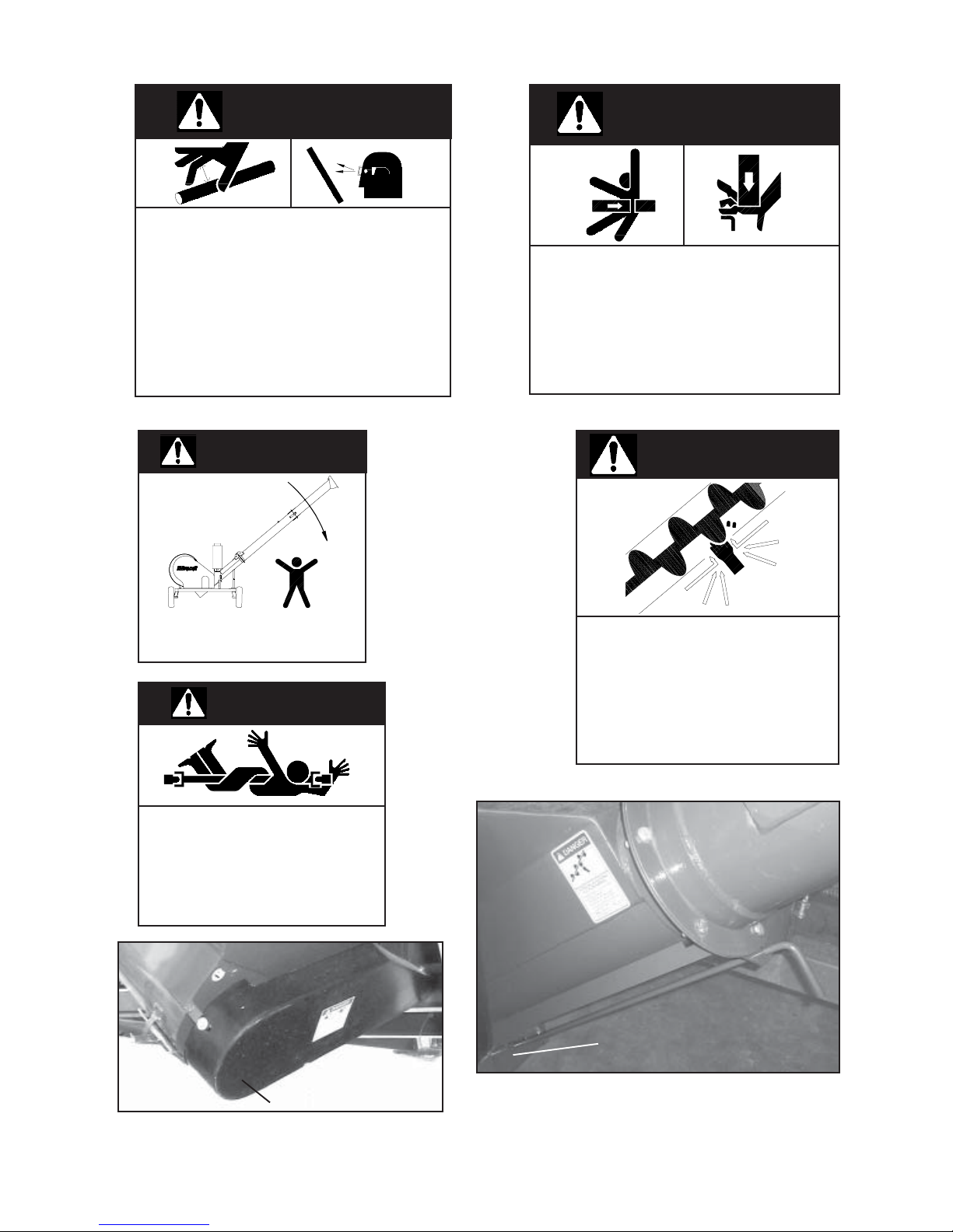
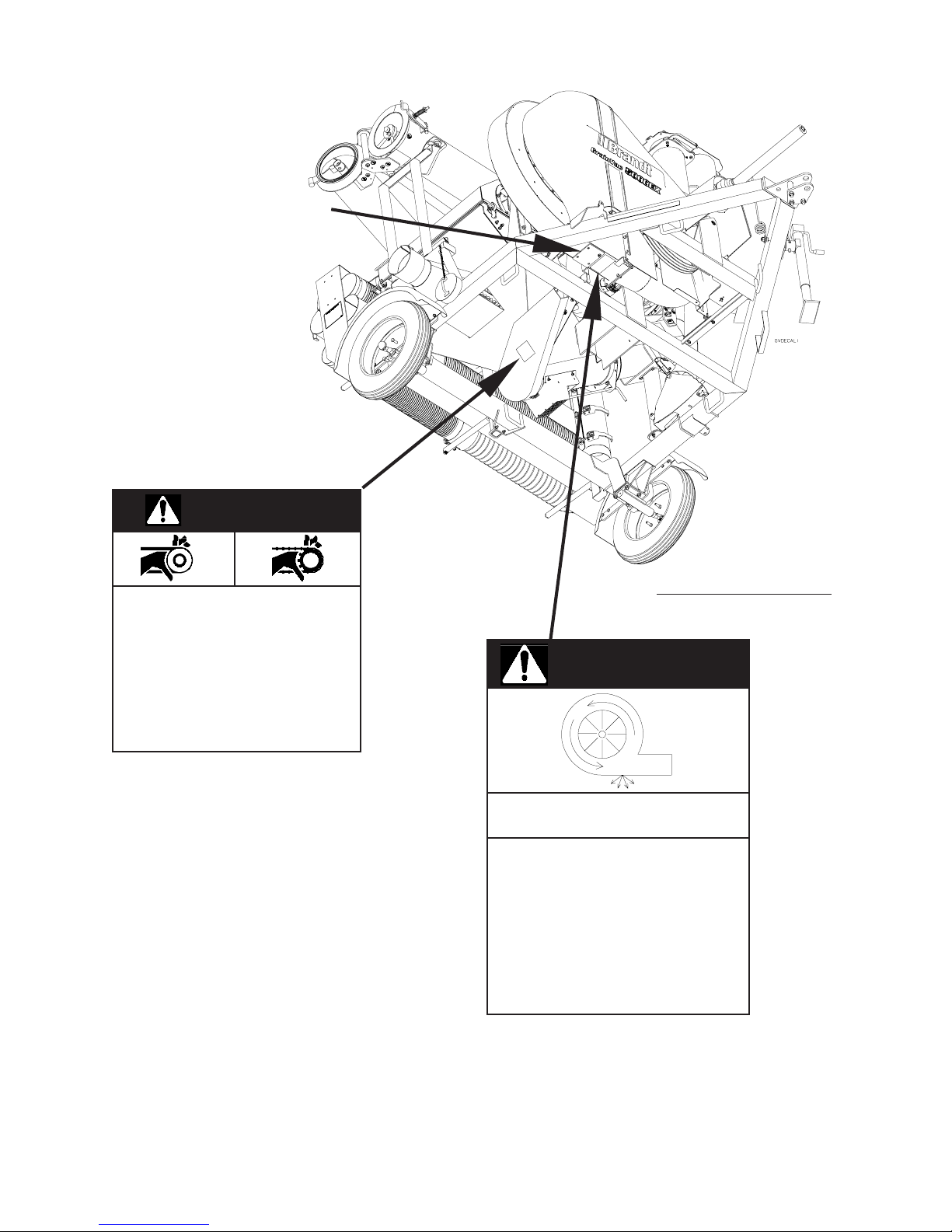
2.8 Safety Decal Locations
The following illustration shows the position and content of the various safety decals on the Brandt Grain
Vac 5000. If safety decals ever become damaged, removed or illegible, new decals must be applied.
New decals are available from your authorized dealer.
1
DANGER
8
3
4
7
9
5
6
10
2
MOVING PART HAZARD
To prevent serious injury or death from moving parts:
• KEEP AWAY, Moving parts can crush and
dismember.
• Do not operate without guards and shields in place.
• Close and secure guards and shields before
starting.
• Keep hands, feet, hair and clothing away from
moving parts.
• Disconnect and lockout power source before
adjusting or servicing.
• Do not stand or climb on machine when operating.
B029111
1
D
3
ECAL LOCATIONS
2
DANGER
CAUTION
PTO SPEED - 1000 RPM
1. Read and understand the operator’s manual before operating.
2. Keep all safety shields and devises in place.
3. Make certain everyone is clear before operating or moving
the machine.
4. Keep hands, feet and clothing away from all moving parts.
5. Shut off power to adjust, service or clean the auger.
6. Support discharge end or anchor intake to prevent upending.
(See Operator’s Manual)
7. Disconnect power before resetting motor overload. (electric
Motor Drive)
8. Empty auger before moving to prevent upending.
9. Lower auger to transport position before moving or
transporting.
10. Make certain electric motors are grounded.
11. Use only genuine Brandt replacement parts, especially
shear pins and bolts.
12. Do not run this auger empty except at idling speed.
B029010
5
KEEP ALL SAFETY
SHIELDS IN PLACE
FAILURE TO DO SO WILL
RESULT IN SERIOUS
INJURY OR DEATH
B029175
DANGER
ELECTROCUTION HAZARD
To prevent serious injury or death from
electrocution:
• Stay away from overhead power
lines when transporting or raising
wings.
This machine is not grounded.
Electrocution can occur without direct
contact.
B029050
4
CAUTION
HEARING PROTECTION
REQUIRED HERE
16
6
WARNING
HIGH-PRESSURE FLUID HAZARD
To prevent serious injury or death:
• Relieve pressure on system before
repairing or adjusting or disconnecting.
• Wear proper hand and eye protection
when searching for leaks. Use wood
or cardboard instead of hands.
• Keep all components in good repair.
B029350
7
DANGER
To prevent serious injury or death
from pinching:
•Keep all persons and objects clear
while any part of this machine is in
motion.
B029111
8
WARNING
TIPPING HAZARD
To prevent serious injury or death:
DO NOT TRANSPORT GRAIN VAC WITH
AUGER IN EXTENDED POSITION
9
ROTATING DRIVELINE HAZARD
To prevent serious injury or death from rotaing
driveline:
• Keep all guards in place when operating.
• Operate only at 1000 RPM.
• Keep hands, feet, hair and clothing away
from moving parts.
DANGER
B029071
B029170
10
10
DANGER
ROTATING AUGER AND
SUCTION HAZARD
To Prevent Serious Injury Or Death
From Rotating Auger:
- Stop engine, set park brake,
remove ignition key and wait for
all moving parts to stop before
inspecting or servicing.
- Make sure door is closed before
starting machine. B029235
1
Lower Chain Guard
D
ECAL LOCATIONS
17
Lower Body Clean Out
Fan Inspection Cover
DANGER
MOVING PART HAZARD
To prevent serious injury or death from moving parts:
• KEEP AWAY, Moving parts can crush and
dismember.
• Do not operate without guards and shields in place.
• Close and secure guards and shields before
starting.
• Keep hands, feet, hair and clothing away from
moving parts.
• Disconnect and lockout power source before
adjusting or servicing.
• Do not stand or climb on machine when operating.
B029111
View from under the Vac
DANGER
THROWN OBJECT HAZARD
AIR BLAST HAZARD
TO PREVENT SERIOUS INJURY OR
DEATH FROM ROTATING FAN:
- Stop engine, set park brake,
remove ignition key and wait for all
moving parts to stop before
inspecting or servicing.
- Wear proper hand & eye protection when
inspecting & servicing.
- Make sure access door is secured
before starting machine.
B029276
18

Section 3 - Operation
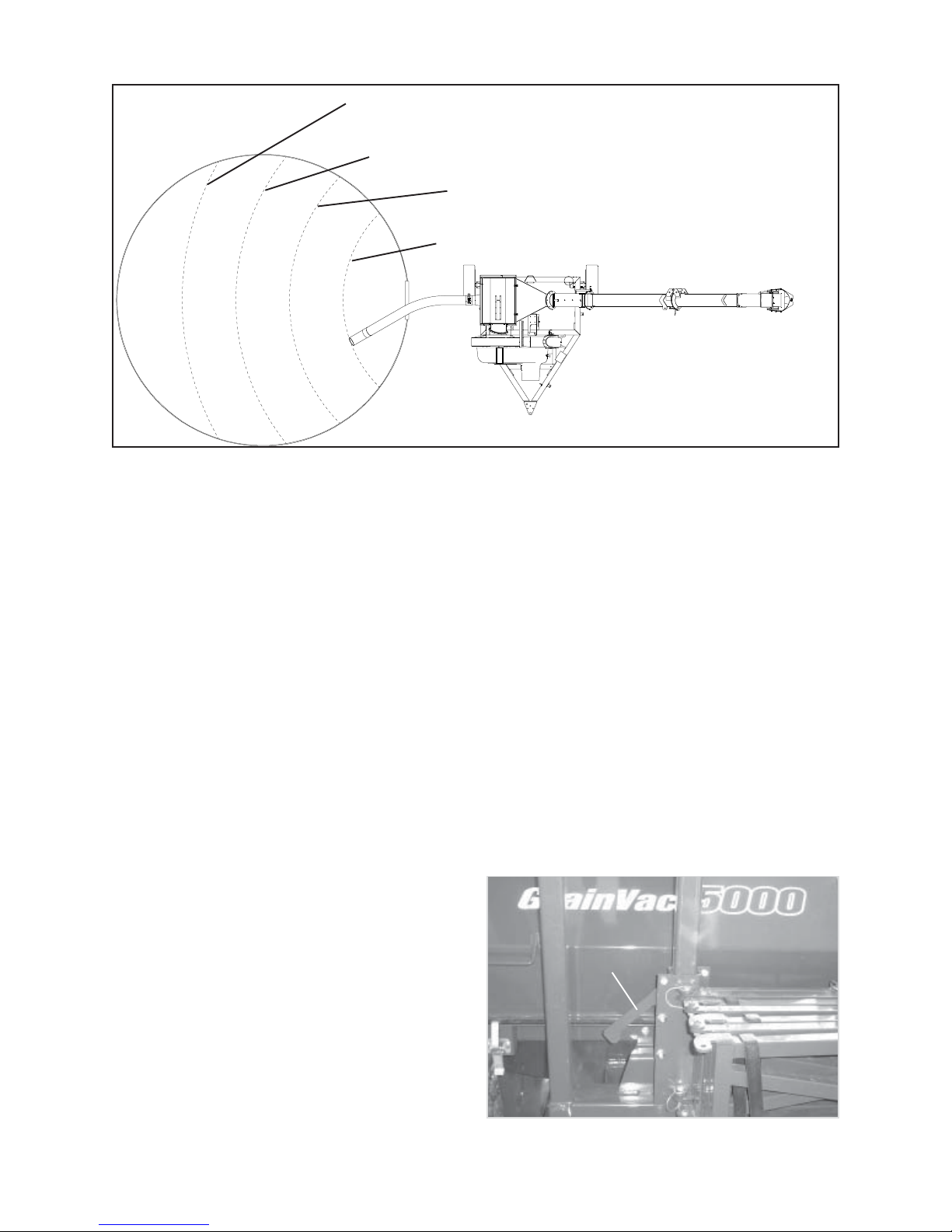
3.1 Principles of Operation
The Brandt Grain Vac 5000 uses a centrifugal fan to produce a vacuum inside a hollow body. This vacuum
creates a flow of air that conveys granular materials to the body. Once in the body of the machine, the grain
is removed by an auger and the air is drawn from the body by the centrifugal fan. The auger discharges the
grain into the awaiting transport through an airlock door. The airlock door ensures suction from the inlet
hoses only. The air, once drawn from the body, passes through the fan and is discharged through an
exhaust pipe.
The centrifugal fan is belt driven by the tractor PTO. The discharge auger position is controlled by tractor
hydraulics and the flighting is chain driven by the tractor PTO.
H
G
C
D
FIG. 1 PRINCIPLES OF OPERATION
A Fan
B Bin Snake
C Suction Hoses
D Cleanup Nozzle
E Machine Body
F Discharge Auger
G Airlock
C
B
B
D
E
E
A
A
G
F
F
19

3.2 First Operation
A. Before starting:
1. Read operator’s manual.
D. After 100 hours:
1. Check oil level in auger drive gearbox. The
gearbox should be half full of oil. Fill with
S.A.E. 80W90 gear oil if required.
2. Hand turn PTO shaft to ensure fan and auger
turn freely.
3. Tighten wheel bolts to specified torque.
4. Close the lower body clean out.
5. Check all fasteners and ensure they are tightened
to specified torque levels.
6. Do the Run-in procedure for the PTO shaft
clutch as shown on page 53.
B. Initial Break-in
Run 300 - 400 bushels slowly through the
Vac at 75% rated PTO speed to polish the
rust from the inside of the auger tubes and
then:
1. Stop and check fan drive belt tension. New
belts stretch noticeably upon initial use. It
is crucial that the belts are tightened as
specified at this time. If the fan belts are
not tightened, they will fail.
2. Check auger chain drive tension.
3. Hand turn PTO to ensure fan and auger turn
freely.
C. After 5 and after 20 hours:
1. Check fan drive belt and auger drive chain
tension.
2. Hand turn PTO shaft to ensure fan and auger
turn freely.
3. After the 20 hour inspection, go to the regular
maintenance schedule outlined in the
Maintenance section of this manual.
E. After the Vac has been unused
after approximately a month:
1. Check the inside of the auger tubes for rust build
up. If the tubes are rusty, go through the initial
break-in procedure.
3.3 Pre-Operation Checklist
Before operating the Grain Vac and each time
thereafter, the following areas should be checked.
1. Check the PTO shaft to ensure that it is locked
into position on the tractor and machine shafts.
2. Insure the PTO driveline shield turns freely on
the shaft.
3. Service the machine as per the schedule in the
maintenance section of this manual.
4. Make sure all guards and shields are in place
and in good repair.
5. Check tires for proper inflation and be sure they
are in safe road condition.
6. Use only a tractor of adequate power to operate
the Grain Vac. For the Brandt Grain Vac 5000,
we recommend minimum of 70 HP.
7. Inspect hydraulic lines and hose ends for signs
of wear and check all fittings for leaks.
8. Be sure the draw bar pin is securely fastened
and retained in place.
9. Be sure the auger fold is adjusted properly so
the auger is fully extended when ram reaches
full stroke.
20

10. Check and clean the auger of obstructions that
may have hung up on internal hanger bearing
mounts.
11. Visually check the auger drive chain for dryness.
If the chain appears to be dry, it should be
lubricated with either a commercial aerosol chain
lubricant or a light oil.
12. Besure the lower body clean out is closed.
3.4 Equipment Matching
The Brandt Grain Vac 5000 was designed to be
used with agricultural tractors with the following
specifications:
-A minimum of 70 PTO horsepower
-The tractor PTO stub shaft must be 1000 rpm, 21
spline, 1 3/8” diameter. Do not use on a tractor
with 540 rpm PTO as there will be insufficient fan
speed to convey material.
-The tractor drawbar dimension must be 16 inches
(40 cm) from the end of the PTO stub shaft and the
centre of the drawbar hitch pin hole, see Figure 2.
Consult your tractor manual for the drawbar
adjustment procedure.
16”
End of Tractor
PTO Stub Shaft
Centreline of
Drawbar Hole
FIG. 2 DRAWBAR DIMENSIONS
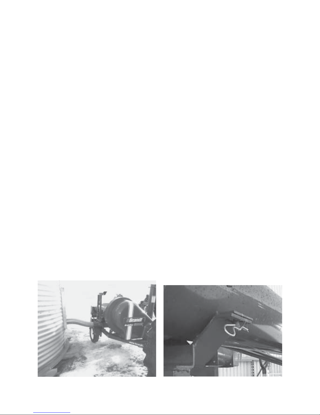
3.5 Attaching / Unhooking
The Grain Vac should be parked on a level, dry
area that is free of debris and foreign objects. Use
the following procedure when hooking or unhooking
the Grain Vac.
A. To Hook to a Tractor
1. Clear all bystanders, especially children from the
area.
2. Make sure there is enough room to back the
tractor up to the hitch point.
-The tractor hydraulic system must have one double
acting remote valve to operate the discharge auger
folding system. It must be capable of 2000 PSI at
an adequate flow to position the auger in a suitable
time. Either open or closed centre hydraulic systems
can be used.
-Never run the tractor RPM at greater than rated
PTO speed. Most tractors will allow speeds in
excess of the rated PTO speed. Overspeeding your
Grain Vac in this manner will reduce the life of the
machine, possibly cause serious damage and may
cause injury to the operator or bystanders.
3. Start the tractor and slowly back it up to the
hitch point.
4. Stop the tractor, place the park brake and
remove the ignition key before dismounting.
5. Install a drawbar pin with provisions for a
mechanical retainer. Install the mechanical
retainer.
6. Raise the implement hitch jack and rotate 90°
to place into it’s stowed position.
21

7. Hook up the provided safety chain to the tractor
drawbar.
B. To Hook to a Truck
1. Clear the area of bystanders, especially children.
8. Connect the PTO shaft:
-Check that the guard on the PTO shaft rotates
freely.
-Check that the PTO shaft telescopes freely and
that the shaft has been serviced as per the
lubrication schedule outlined in this manual.
-Attach to tractor by retracting the locking collar
and sliding onto the tractor PTO stub shaft. It
may be necessary to rotate the PTO shaft slightly
to get it aligned. Once the shaft is started onto
the tractor shaft, release the locking collar and
slide on until locking collar clicks into place.
-Check that it is firmly locked in place by pulling
and pushing on it to check for movement.
9. Connect the hydraulics. The Grain Vac 5000
comes factory equipped with Pioneer ends. If
your tractor has different couplers, you will need
a set of adaptors or will need to change the ends
on the Grain Vac to match your tractor. Use a
clean cloth or paper towel to clean the ends and
the area around the couplers on the tractor.
Insert the ends into the couplers until they seat
firmly.
10. Ensure the hydraulic lines are routed so they are
not dragging on the ground and are not touching
the PTO shaft.
2. Start the truck and slowly back into the hitch.
3. Stop the engine, place in park, set park brake
and remove ignition key before leaving cab.
4. Install a drawbar pin with provisions for a
mechanical locking device. Install mechanical
locking device.
5. Raise the implement hitch jack and rotate 90°
to place into it’s stowed position.
6. Hook up the provided safety chain to the frame
of the truck.
7. Ensure hydraulic hose ends are stored in the
provided storage holder and hoses are secured
on the mount.
8. The PTO shaft can be stored in the PTO storage
post and secured in place. If the tow vehicle
has a back window in the tailgate, the upper
end of the PTO shaft should be removed and
transported in the back of the truck. The PTO
shaft simply slides apart.
11. When unhooking from the tractor, reverse the
above procedure.
FIG. 4 ATTACHED - TRUCKFIG. 3 ATTACHED - TRACTOR
22
3.6 Setup For Operation
Before the Grain Vac can be used, it must be set up
and positioned, ready for operation. When
preparing for operation use the following procedure.
1. Clear the area of bystanders, especially children.
7. Rotate the plastic Discharge Nozzle into working
position. Point the nozzle so it will direction the
discharge air down wind.
8. Attach the PTO Shaft to the tractor, making the
safety lock is engaged.
2. Select a position so there is adequate room for
the tractor, Grain Vac, truck and operator to
manoeuvre safely.
3. Check for overhead obstructions and power
lines at the site to ensure there is enough
clearance to place the auger into operation
position.
4. For unloading from a full bin, position the grain
vac as close as possible to the bin door so that
one of the 3 1/2 foot stainless steel hoses ends
flush with the door. See Fig. 5.
5 Open bin lid to avoid bin damage.
6. Unfold the auger into operating position,
remembering first to remove the safety pin in
the transport rest. See Fig. 6. Place all controls
in neutral and set park brake before dismounting.
3.7 Operation
A. General Operating Instructions
1. Clear the area of all bystanders especially
children.
2. Be sure you and all others in the area are wearing
ear protection.
3. Damp or wet grain is more difficult to convey
than dry grain. Allow more air than grain to
enter the inlet in these situations.
4. In light crops such as oats or barley, care should
be taken not to over feed the 10” unloading
auger. This will cause the vac body to fill up
with grain and possibly cause material to be
expelled out through the exhaust pipe. If this
occurs, refer to section E, page 26 for help.
NOTE: Feather the hydraulics when extending
the auger, especially at the point when the
tubes overcentre. Damage to the machine
can occur.
5. In pulse crops such as peas and lentils, that will
crack easily, we recommend the vac be slowed
down to 80% of recommended PTO speed
(800 RPM) during cleanup operations. The
material is damaged within the unloading
FIG. 6 TRANSPORT SAFETY PINFIG. 5 FULL BIN SETUP
23
augerwhen running at full speed in low capacity
situations such as cleanup.
6. The Grain Vac is a precision piece of equipment.
However it is relatively insensitive to dust and
debris. Common sense should be used to keep
dirt and debris to a minimum. Nothing big
enough to stop the internal auger should be put
through the vac. Material like cloth or plastic
should not be put through the vac as it will hang
up on the internal hanger bearings within the
auger.
7. Any dust and fine particles like chaff is passed
out of the Grain Vac through the exhaust pipe.
This feature will provide the operator with a
virtually dust free environment in the bin while
loading grain.
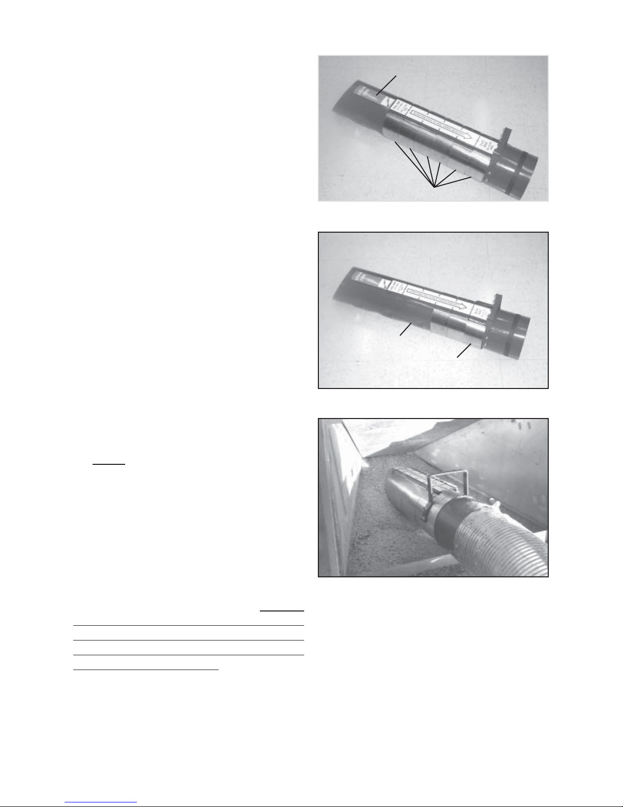
Green ‘Grain Zone’ Decal
Stainless Spring Clips
FIG. 7 MAXFLO FULL BIN NOZZLE
Exposed Holes
B. Full Bin Unload
To obtain the best capacity with your Grain Vac,
you MUST allow air in with the grain. The MaxFlo
Full Bin Nozzle has been designed to offer the
operator an easy way of adjusting the amount of air
that is allowed into the system. It has a series of
holes in the bottom which allow air into the hose.
The positioning of these holes allows the grain to
float on a cushion of air, thus making the grain easier
to move.
Six stainless spring clips are used to adjust the number
of holes that are exposed. See Fig. 7. As hoses
are added to the nozzle, more holes in the nozzle
must be exposed. The amount of pulsing or
surging at the nozzle will dictate the number of
holes that must be exposed. The clips must be
moved back towards the handle until the pulsing or
surging stops. See Fig. 7A. This will be slightly
different for every length of hose and every different
product being moved.
Spring Clips moved back
and stacked against the Handle
FIG. 7A EXPOSING HOLES IN THE NOZZLE
FIG. 8 MAXFLO NOZZLE IN A FULL BIN
1. Insert the MaxFlo Nozzle into the chute of the
bin until the green ‘Grain Zone’ decal is just
covered. See Fig. 8. All six stainless steel clips
should be in position. The only holes exposed
should be the ten holes under the ‘Grain Zone’
decal.
2. Connect the Nozzle to the Vac using a 3 1/2’
steel flex hose.
24

3. With the tractor at slightly over idle speed, gently
ease the PTO control to the ON position. With
some newer tractors, the PTO control is either
on or off with no ability to ease the clutch on.
For these tractors we recommend that the tractor
throttle be set at idle.
4. With the tractor PTO on and the Vac turning
slowly, gradually increase the throttle until it
reached full rated PTO speed. Remember not
to overspeed your Grain Vac and not to run your
brand new Grain Vac at full RPM for the first
15 minutes of operation.
5. Go to the bin and observe the grain flow into
the nozzle. If the flow of grain is erratic as
in a glupping sensation, slide the end spring
clip back towards the handle until a steady
stream of grain is flowing through the nozzle.
This ensures an adequate mix of air and grain
for optimal conveying capacity. A slight pulsing
in the hose is normal.
6. When the truck is full, there is no requirement
to empty the machine unless you intend to move
to a new site. You may just shut off the PTO.
C. Removing the Grain from in a
Clean Up Operation
1. When first entering the bin, we suggest that you
bring in all the hoses you will require to get to
the back of the bin. Also bring the flexible rubber
hose and the Clean Up Shovel. Do not attach
any of the hoses at this time. This will simply
save time when it comes time to lengthen the
hose.
2. Replace the 3 1/2’ steel flex hose ( if installed
on the vac) with a 7’ steel flex hose. The MaxFlo
Full Bin Nozzle should be used on the end of
the hose to maximize capacity.
3. When inserting the nozzle into the grain, arc the
middle of the hose up and keep the end of the
MaxFlo Nozzle on the floor. See Fig. 8A.
4. Push down on the arc in the hose and drive the
nozzle into the bottom of the pile. You can insert
the MaxFlo Full Bin Nozzle deeper into the grain
than what the “Grain Zone’ decal shows. A slight
surging may be heard or felt but it will quickly
go away. If the flow of grain completely stops,
move the end spring clip back to expose more
holes. When the end of the MaxFlo nozzle
becomes fully exposed out of the grain, move
the hose over a few feet and repeat the same
procedure.
Push down on the Hose
to insert the MaxFlo Nozzle
deeper into the pile of grain.
FIG. 8A NOZZLE INSERTED IN GRAIN PILE
25
two 7’ Steel Flex & one 3.5’ Steel Flex Hose - 4 Spring Clips
moved on MaxFlo Nozzle
two 7’ Steel Flex Hoses - 3 Spring Clips moved on MaxFlo Nozzle
one 7’ Steel Flex & one 3.5’ Steel Flex Hose - 2 Spring
Clips moved on MaxFlo Nozzle
one 7’ Steel Flex Hose - 1 Spring Clip moved on MaxFlo
Nozzle
FIG. 9 ADDING HOSE AND MOVING IN AN A RC A CROSS THE BIN
5. Move the hose in an arc, from side to side in the
bin. See Fig. 9. Add only 3.5’ of hose at a time
when required.
6. Continue moving grain until you have reached
the back of the bin. Use the steel flexible hoses
as long as possible to maximize capacity and
minimize wear. Use straight solid sections when
ever possible.
7. After you have reached the back of the bin with
the MaxFlo Nozzle, remove the last section of
steel hose and the MaxFlo Nozzle. Attach the
flexible rubber hose and the Cleanup Shovel and
proceed with final cleanup.
8. Start cleaning at the back of the bin and work
your way forward, toward the door. Clean
directly in front of the door last. You can remove
sections of flexible steel hose as you get closer
to the door.
D. Optional Adjustable Bin Snake
To ensure ease of use during bin cleanup situations
your new Grain Vac can be equipped with an
optional adjustable height Bin Snake. This will ensure
that the bin snake can accommodate most any bin
door height.
1. To raise the height of the Bin Snake assembly
simple lift the latch handle and slide the snake
upward to match your bin door.
2. Once the desired height has been reached,
simply latch the handle back into one of the
adjustment holes as indicated in Figure 10.
Latch Handle
The MaxFlo Full Bin Nozzle should
be used in all grain moving situations
except for final floor cleanup.
FIG. 10 ADJUSTABLE HEIGHT BIN SNAKE
26

3. To lower the Bin Snake assembly, raise the
assembly slightly, just enough to take the pressure
off of the latch handle.
4. Lift the latch handle open and then slide the Bin
Snake down to your desired position. Lock in
place with the latch handle.
Using the Optional Bin Snake
1. After you have reached the back of the bin with
the MaxFlo Nozzle, from within the bin, unlatch
the rubber retaining strap holding the Bin Snake
in transport and unfold it into the bin one section
at a time. As each section is unfolded, the hose
should be raised up and strapped under the Bin
Snake. When all the Bin Snake sections are
attached to the hose, you are ready to cleanup
the floor of the bin. Extra Bin Snake sections
are available to reach further into larger than
average bins.
E. Adjustable Air Throttle and Vent
The Grain Vac comes equipped with a unique feature
that decreases the horsepower requirement of the
unit. It consists of an internal damper plate that senses
high airflow, and hence high horsepower situations
and moves into position to limit the condition.
The damper plate is controlled by an external spring.
The condition of this spring should be checked
visually occasionally and should be replaced if it
appears to be sprung or damaged.
The Air Throttle is normally set in the unpinned
position in which the spring controls the position of
the damper plate. This position is used for most
products.
1. If you experience the air throttle fluttering,
adjustment should be made. To correct this
problem simply tighten the adjusting bolt (see
Figure 11) until the flutter is removed.
2. Remove the last section of steel hose and the
Full Bin Nozzle. Attach the flexible rubber hose
and the Cleanup Shovel and proceed with final
cleanup.
3. Start cleaning at the back of the bin and work
your way forward, toward the door. Clean
directly in front of the door last. You can remove
sections of flexible steel hose as you get closer
to the door.
4. When bin clean up is complete, lower the Bin
Snake to it’s lowest position before lowering
the auger.
2. If the throttle is not moving, check the assembly
for binding. Loosening the tension spring may
also be required.
Spring
Adjustment
Bolt
FIG. 10A CLEANUP SETUP
FIG. 11 ADJUSTABLE A IR THROTTLE
27
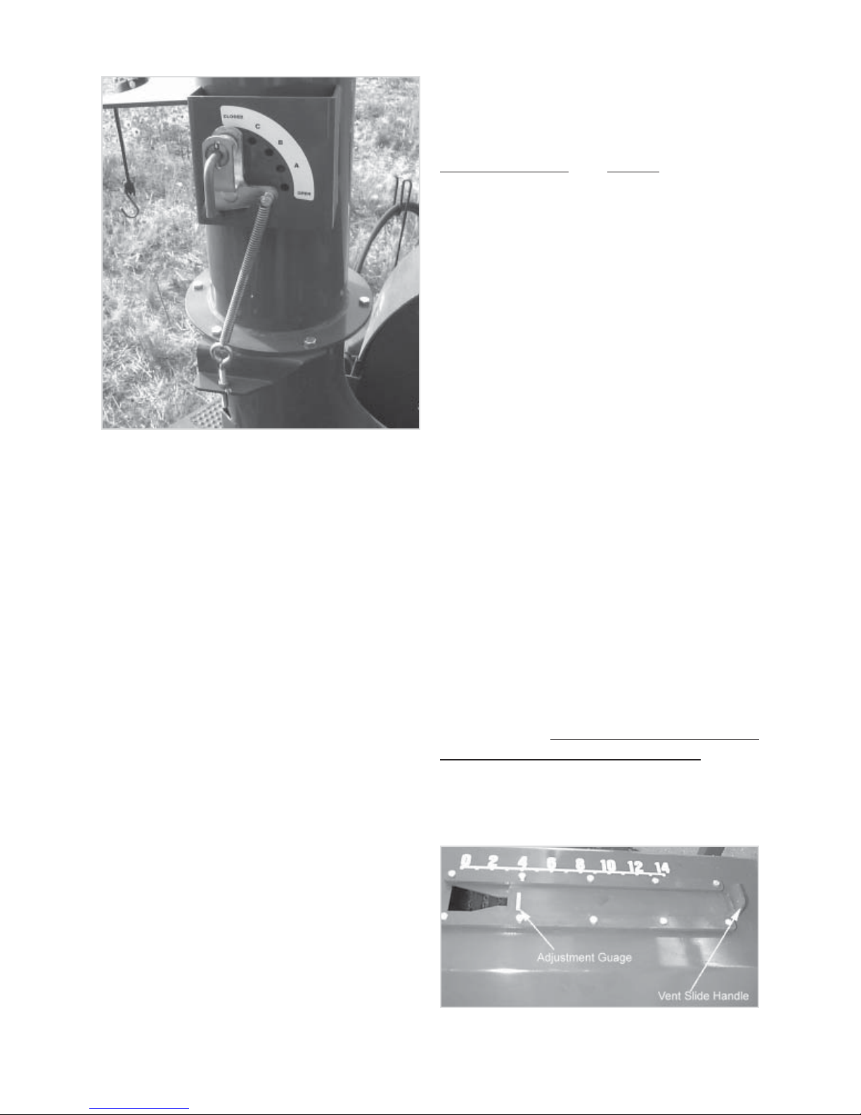
FIG. 12 AIR THROTTLE PINNED CLOSED
The manual settings in the Air Throttle and the use
of the Adjustable Vent Slide, located in the top of
the upper body, should be used when you are moving
lighter products such as light oats or barley,
sunflowers or grasses, to reduce the amount of
product being discharged through the exhaust tube.
The product carrying capacity of the airstream within
the intake hoses is directly related to the velocity of
the air within the suction hose(s). Therefore, in many
cases with light bulky products, the product carrying
capacity of the Grain Vac is too great to allow
separation of the product from the airstream in the
Grain Vac body. By manually closing the Air Throttle
and opening the intake vent in the upper body, we
decrease the volume of air travelling through the
suction hose and therefore the velocity, thus allowing
separation of the grain particles from the airstream.
Although it is difficult to give an exact specification
of throttle positioning and intake vent opening for
each product because of differences in bushel weight,
the following chart can be used as a guide. In any
case, it is important to ensure that the air inlet at the
suction hose end is not choked off excessively.
In all cases, set the Air Throttle to the position shown
below and use the Vent Slide to do the fine
adjustment.
Air Throttle Position Product
A Light Oats or Barley
B Sunflowers
C Grasses
If the closing of the throttle and the intake vent
opening is still insufficient to eliminate product
discharge through the exhaust, try one or all of the
following:
A - Decrease the PTO speed.
B - Increase the length of the intake hose.
C - Allow more air at the intake end of the hose.
The manual positioning of the Air Throttle and
opening of the intake vent should only be used if
you are experiencing product discharge from the
exhaust. If the body is full, you must open the vent
fully and remove the intake hose from the grain to
allow the Grain Vac to clean itself out before
resuming normal operation.
The Air Throttle can also be pinned in the fully open
position. This position should only be used when all
the hoses are connected to the vac and you are
moving heavy product. This will give you the highest
capacity available, but will require more horsepower
from the tractor. This position must not be used
when vaccing under normal conditions. Because
of the large amount of air flow the fan can produce,
excessive strain can be put onto the slip clutch in the
PTO shaft causing it to slip and damage the clutch
pack.
FIG. 13 ADJUSTABLE VENT SLIDE
28

F. Folding Exhaust Deflector
3.8 Shutdown
To enable you to control the exhausting air from the
Grain Vac, Brandt has provided an exhaust deflector.
This deflector can pivot around 360 degrees to
ensure you are able to properly deflect the exhaust
air. This deflector also folds down for transport.
1. To rotate the exhaust deflector, open the rotation
lock handle as seen in Figure 14. Rotate to the
desired position and relock with the rotation
locking handle.
2. To fold into transport position, release folding
latch and fold the exhaust deflector down against
the silencer as seen in Figure 14.
3. Use the rubber strap on the Exhaust Stack to
hold the Exhaust Deflector in place while the
vac is being transported. See Figure 15.
Folding
Latch
1. When stopping the Grain Vac before you have
intentions to move to a new location, all you
have to do is slow down the tractor RPM and
then shut off the PTO. No special care must be
taken to empty the machine.
2. When finished a job and you will be transporting
the unit, it is best that the RPM of the tractor be
slowed to an idle and the Grain Vac be allowed
to run at slow speeds for 20 to 30 seconds to
empty the auger, vac body and hoses of grain.
3. If the Bin Snake was used during cleanup, it is
recommended that you start at the bin end and
fold each section as you let the hose down.
Once at the vac body, secure in place with strap
provided. Ensure the Bin Snake is in it’s
lowest mounting position before transport.
Failure to do this will result in damage to
the Bin Snake when the auger is folded.
Rotation
Handle
FIG. 14 FOLDING EXHAUST DEFLECTOR
Rubber
Strap
4. Reinstall all hoses and nozzles used during the
job back into the transport racks on the machine.
5. Reinstall the suction inlet plug into the suction
inlet.
6. With the tractor hydraulics, fold the auger down
into transport position. Reinstall transport safety
pins.
FIG. 15 FOLDING EXHAUST DEFLECTOR
29
 Loading...